Page 3483 of 3924
PS-28
< SERVICE INFORMATION >
POWER STEERING OIL PUMP
Before starting work, confirm belt tension is proper.
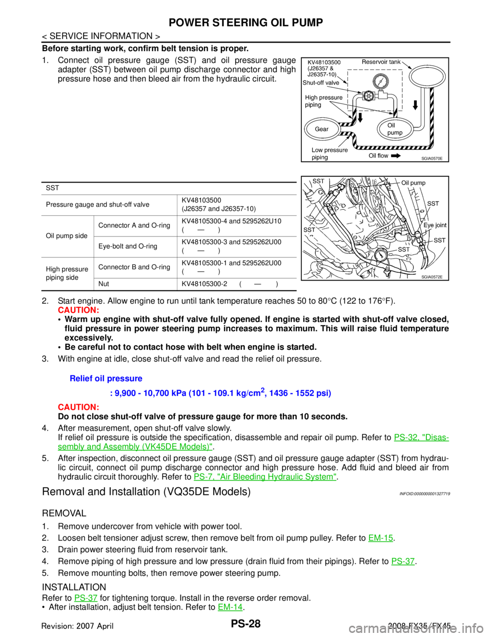
1. Connect oil pressure gauge (SST) and oil pressure gaugeadapter (SST) between oil pump discharge connector and high
pressure hose and then bleed air from the hydraulic circuit.
2. Start engine. Allow engine to run until tank temperature reaches 50 to 80 °C (122 to 176 °F).
CAUTION:
Warm up engine with shut-off val ve fully opened. If engine is started with shut-off valve closed,
fluid pressure in power steering pump increases to maximum. This will raise fluid temperature
excessively.
Be careful not to contact hose with belt when engine is started.
3. With engine at idle, close shut-off valve and read the relief oil pressure.
CAUTION:
Do not close shut-off valve of pressu re gauge for more than 10 seconds.
4. After measurement, open shut-off valve slowly. If relief oil pressure is outside the specification, disassemble and repair oil pump. Refer to PS-32, "
Disas-
sembly and Assembly (VK45DE Models)".
5. After inspection, disconnect oil pressure gauge (S ST) and oil pressure gauge adapter (SST) from hydrau-
lic circuit, connect oil pump discharge connector and high pressure hose. Add fluid and bleed air from
hydraulic circuit thoroughly. Refer to PS-7, "
Air Bleeding Hydraulic System".
Removal and Installation (VQ35DE Models)INFOID:0000000001327719
REMOVAL
1. Remove undercover from vehicle with power tool.
2. Loosen belt tensioner adjust screw, then remove belt from oil pump pulley. Refer to EM-15
.
3. Drain power steering fluid from reservoir tank.
4. Remove piping of high pressure and low pressure (drain fluid from their pipings). Refer to PS-37
.
5. Remove mounting bolts, then remove power steering pump.
INSTALLATION
Refer to PS-37 for tightening torque. Install in the reverse order removal.
After installation, adjust belt tension. Refer to EM-14
.
SGIA0570E
SST
Pressure gauge and shut-off valveKV48103500
(J26357 and J26357-10)
Oil pump side Connector A and O-ring
KV48105300-4 and 5295262U10
(—)
Eye-bolt and O-ring KV48105300-3 and 5295262U00
(—)
High pressure
piping side Connector B and O-ring
KV48105300-1 and 5295262U00
(—)
Nut KV48105300-2 ( — )
SGIA0572E
Relief oil pressure : 9,900 - 10,700 kPa (101 - 109.1 kg/cm
2, 1436 - 1552 psi)
3AA93ABC3ACD3AC03ACA3AC03AC63AC53A913A773A893A873A873A8E3A773A983AC73AC93AC03AC3
3A893A873A873A8F3A773A9D3AAF3A8A3A8C3A863A9D3AAF3A8B3A8C
Page 3484 of 3924
POWER STEERING OIL PUMPPS-29
< SERVICE INFORMATION >
C
DE
F
H I
J
K L
M A
B
PS
N
O P
After installation, bleed air. Refer to PS-7, "Air Bleeding Hydraulic System".
Removal and Installation (VK45DE Models)INFOID:0000000001327720
REMOVAL
1. Remove undercover from vehicle with power tool.
2. Remove power steering oil pump belt from auto tensioner. Refer to EM-170
.
3. Drain power steering fluid from reservoir tank.
4. Remove piping of high pressure and low pressure from power steering oil pump (drain fluid from their pip- ings). Refer to PS-37
.
5. Remove mounting bolts, then remove power steering pump.
INSTALLATION
Refer to PS-37 for tightening torque. Install in the reverse order removal.
After installation, bleed air. Refer to PS-7, "
Air Bleeding Hydraulic System".
NOTE:
Adjustment of belt tension is no necessary bec ause engine of this model equips auto tensioner.
Disassembly and Assembly (VQ35DE Models)INFOID:0000000001327721
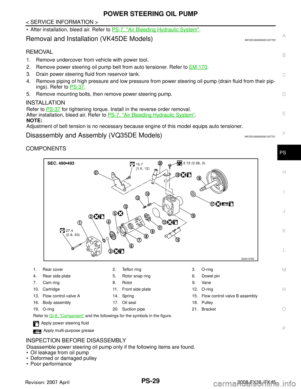
COMPONENTS
INSPECTION BEFORE DISASSEMBLY
Disassemble power steering oil pump only if the following items are found.
Oil leakage from oil pump
Deformed or damaged pulley
Poor performance
1. Rear cover 2. Teflon ring 3. O-ring
4. Rear side plate 5. Rotor snap ring 6. Dowel pin
7. Cam ring 8. Rotor 9. Vane
10. Cartridge 11. Front side plate 12. O-ring
13. Flow control valve A 14. Spring 15. Flow control valve B assembly
16. Body assembly 17. Oil seal 18. Pulley
19. O-ring 20. Suction pipe 21. Bracket
Refer to GI-8, "
Component" and the followings for the symbols in the figure.
: Apply power steering fluid
: Apply multi-purpose grease
SGIA1679E
3AA93ABC3ACD3AC03ACA3AC03AC63AC53A913A773A893A873A873A8E3A773A983AC73AC93AC03AC3
3A893A873A873A8F3A773A9D3AAF3A8A3A8C3A863A9D3AAF3A8B3A8C
Page 3487 of 3924
PS-32
< SERVICE INFORMATION >
POWER STEERING OIL PUMP
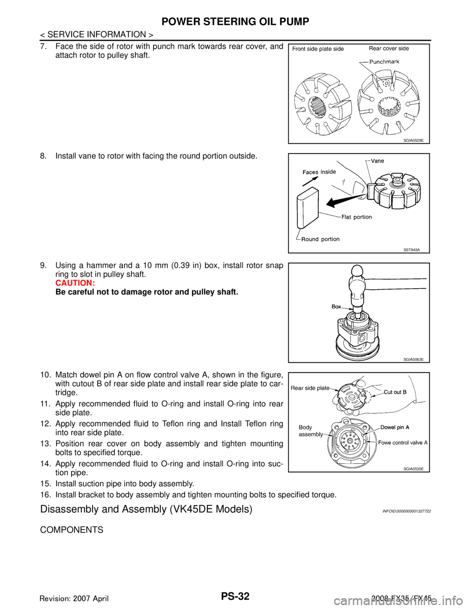
7. Face the side of rotor with punch mark towards rear cover, andattach rotor to pulley shaft.
8. Install vane to rotor with facing the round portion outside.
9. Using a hammer and a 10 mm (0.39 in) box, install rotor snap ring to slot in pulley shaft.
CAUTION:
Be careful not to damage rotor and pulley shaft.
10. Match dowel pin A on flow control valve A, shown in the figure, with cutout B of rear side plate and install rear side plate to car-
tridge.
11. Apply recommended fluid to O-ring and install O-ring into rear side plate.
12. Apply recommended fluid to Teflon ring and Install Teflon ring into rear side plate.
13. Position rear cover on body assembly and tighten mounting bolts to specified torque.
14. Apply recommended fluid to O-ring and install O-ring into suc- tion pipe.
15. Install suction pipe into body assembly.
16. Install bracket to body assembly and tighten mounting bolts to specified torque.
Disassembly and Assemb ly (VK45DE Models)INFOID:0000000001327722
COMPONENTS
SGIA0529E
SST843A
SGIA0063E
SGIA0530E
3AA93ABC3ACD3AC03ACA3AC03AC63AC53A913A773A893A873A873A8E3A773A983AC73AC93AC03AC3
3A893A873A873A8F3A773A9D3AAF3A8A3A8C3A863A9D3AAF3A8B3A8C
Page 3491 of 3924
PS-36
< SERVICE INFORMATION >
POWER STEERING OIL PUMP
7. Install vane to rotor with facing the round portion outside.
8. Check if drive shaft assembly turns smoothly.
9. Install gasket to body assembly.
10. Install rear cover to body assembly and tighten bolts at the spec-ified torque.
11. Install bracket to rear cover and tighten bolts at the specified torque.
12. Install pulley to drive shaft assembly then tighten lock nut at the specified torque.
13. Install spring, flow control valve, O-ring, connector bolt, joint, washer to body assembly. Then tighten lock nut at the specified
torque.
14. Apply recommended fluid to O-ring and Install O-ring to suction pipe.
15. Install suction pipe to body assembly.
SST843A
SGIA0425E
3AA93ABC3ACD3AC03ACA3AC03AC63AC53A913A773A893A873A873A8E3A773A983AC73AC93AC03AC3
3A893A873A873A8F3A773A9D3AAF3A8A3A8C3A863A9D3AAF3A8B3A8C
Page 3494 of 3924
HYDRAULIC LINEPS-39
< SERVICE INFORMATION >
C
DE
F
H I
J
K L
M A
B
PS
N
O P
VK45DE AWD MODEL
Removal and InstallationINFOID:0000000001327724
VQ35DE MODELS
Refer to PS-37, "Component" for tightening torque. Install in the reverse order of removal.
NOTE:
Refer to component parts location and do not reuse non-reusable parts.
JSGIA0219GB
1. Reservoir tank 2. Suction hose 3. High pressure hose
4. Oil cooler 5. Pressure sensor 6. Steering gear assembly
7. Clamp 8. Eye bolt 9. Copper washer
10. Reservoir tank bracket 11. Eye bolt
Refer to GI-8, "
Component" and the followings for the symbols in the figure.
: Apply power steering fluid.
3AA93ABC3ACD3AC03ACA3AC03AC63AC53A913A773A893A873A873A8E3A773A983AC73AC93AC03AC3
3A893A873A873A8F3A773A9D3AAF3A8A3A8C3A863A9D3AAF3A8B3A8C
Page 3495 of 3924
PS-40
< SERVICE INFORMATION >
HYDRAULIC LINE
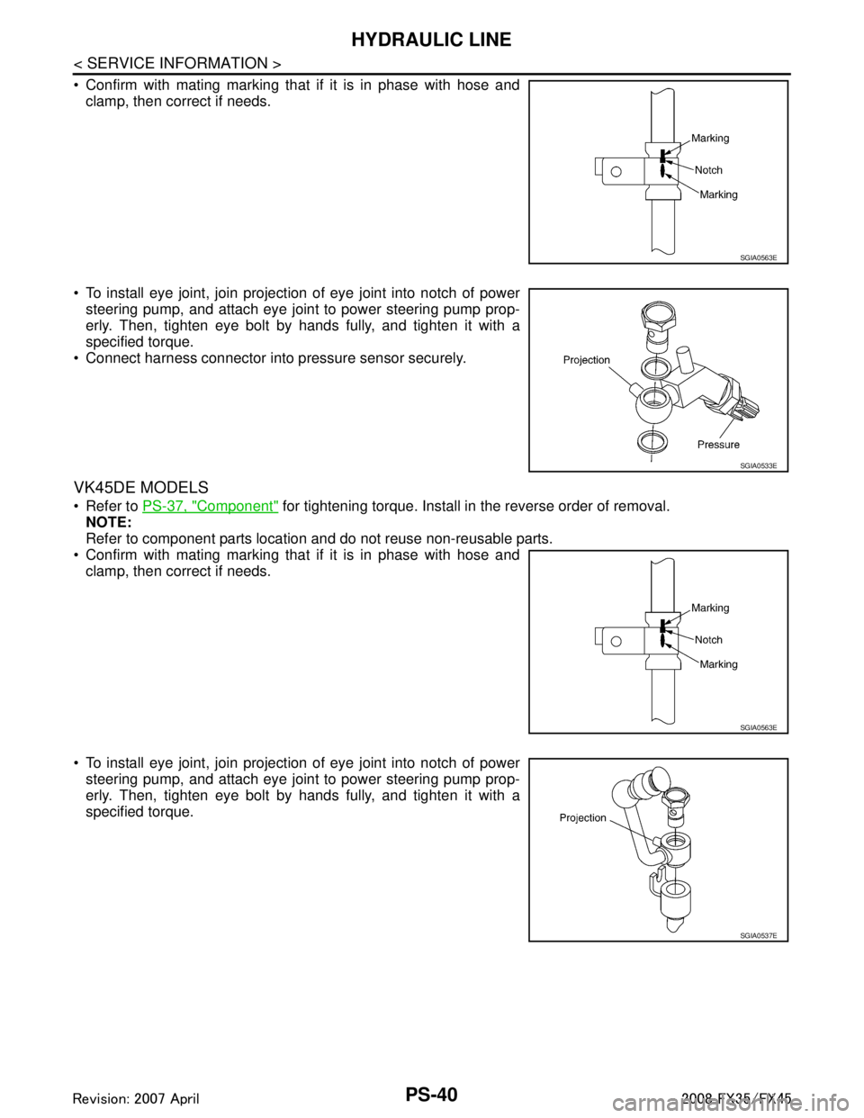
Confirm with mating marking that if it is in phase with hose andclamp, then correct if needs.
To install eye joint, join projection of eye joint into notch of power steering pump, and attach eye joint to power steering pump prop-
erly. Then, tighten eye bolt by hands fully, and tighten it with a
specified torque.
Connect harness connector into pressure sensor securely.
VK45DE MODELS
Refer to PS-37, "Component" for tightening torque. Install in the reverse order of removal.
NOTE:
Refer to component parts location and do not reuse non-reusable parts.
Confirm with mating marking that if it is in phase with hose and clamp, then correct if needs.
To install eye joint, join projection of eye joint into notch of power steering pump, and attach eye joint to power steering pump prop-
erly. Then, tighten eye bolt by hands fully, and tighten it with a
specified torque.
SGIA0563E
SGIA0533E
SGIA0563E
SGIA0537E
3AA93ABC3ACD3AC03ACA3AC03AC63AC53A913A773A893A873A873A8E3A773A983AC73AC93AC03AC3
3A893A873A873A8F3A773A9D3AAF3A8A3A8C3A863A9D3AAF3A8B3A8C
Page 3496 of 3924
SERVICE DATA AND SPECIFICATIONS (SDS)
PS-41
< SERVICE INFORMATION >
C
D E
F
H I
J
K L
M A
B
PS
N
O P
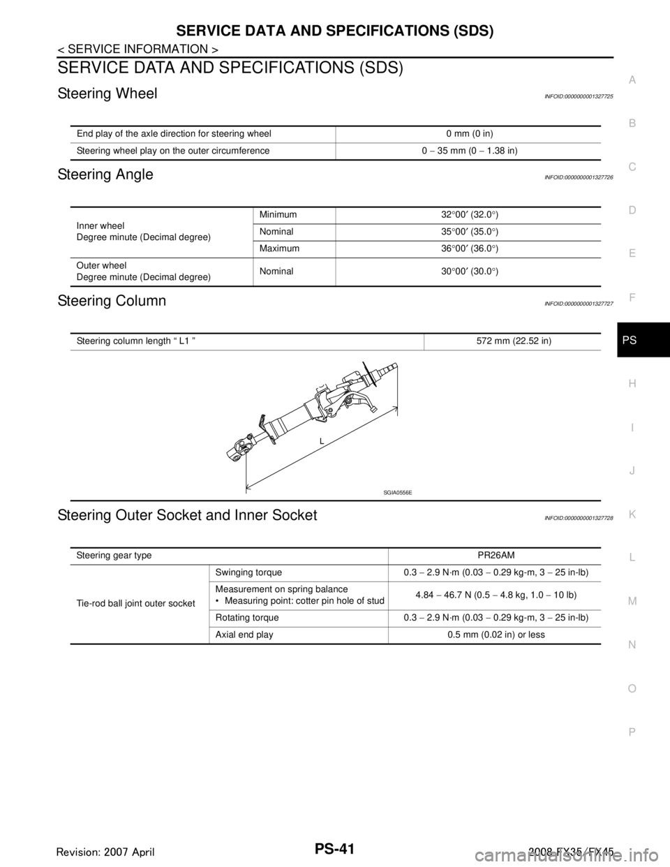
SERVICE DATA AND SPECIFICATIONS (SDS)
Steering WheelINFOID:0000000001327725
Steering AngleINFOID:0000000001327726
Steering ColumnINFOID:0000000001327727
Steering Outer Socket and Inner SocketINFOID:0000000001327728
End play of the axle direction for steering wheel 0 mm (0 in)
Steering wheel play on the outer circumference 0 − 35 mm (0 − 1.38 in)
Inner wheel
Degree minute (Decimal degree) Minimum 32
°00 ′ (32.0 °)
Nominal 35 °00 ′ (35.0 °)
Maximum 36 °00 ′ (36.0 °)
Outer wheel
Degree minute (Decimal degree) Nominal 30
°00 ′ (30.0 °)
Steering column length “ L1 ” 572 mm (22.52 in)
SGIA0556E
Steering gear type PR26AM
Tie-rod ball joint outer socket Swinging torque 0.3
− 2.9 N·m (0.03 − 0.29 kg-m, 3 − 25 in-lb)
Measurement on spring balance
Measuring point: cotter pin hole of stud 4.84
− 46.7 N (0.5 − 4.8 kg, 1.0 − 10 lb)
Rotating torque 0.3 − 2.9 N·m (0.03 − 0.29 kg-m, 3 − 25 in-lb)
Axial end play 0.5 mm (0.02 in) or less
3AA93ABC3ACD3AC03ACA3AC03AC63AC53A913A773A893A873A873A8E3A773A983AC73AC93AC03AC3
3A893A873A873A8F3A773A9D3AAF3A8A3A8C3A863A9D3AAF3A8B3A8C
Page 3497 of 3924
PS-42
< SERVICE INFORMATION >
SERVICE DATA AND SPECIFICATIONS (SDS)
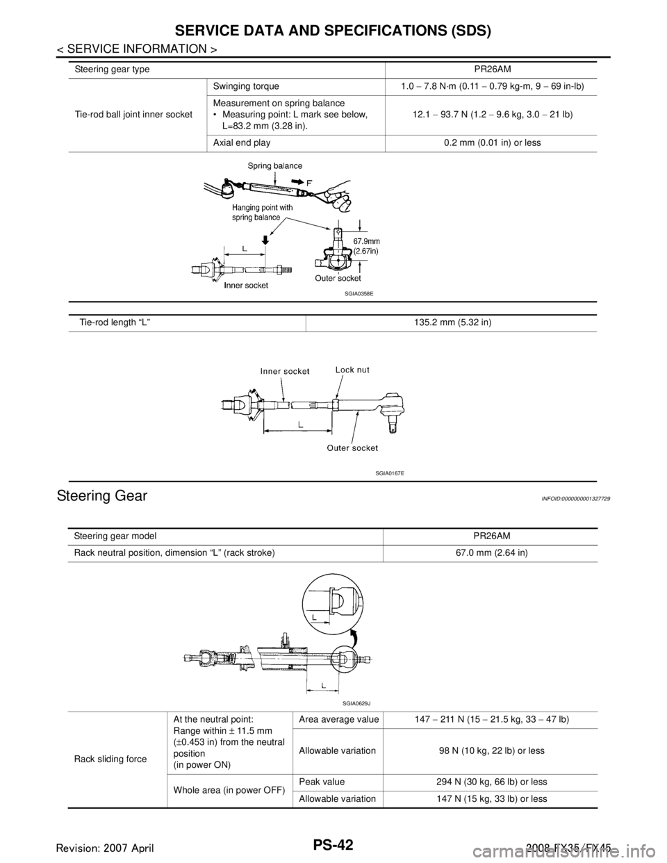
Steering Gear
INFOID:0000000001327729
Tie-rod ball joint inner socket Swinging torque 1.0
− 7.8 N·m (0.11 − 0.79 kg-m, 9 − 69 in-lb)
Measurement on spring balance
Measuring point: L mark see below, L=83.2 mm (3.28 in). 12.1
− 93.7 N (1.2 − 9.6 kg, 3.0 − 21 lb)
Axial end play 0.2 mm (0.01 in) or less
Tie-rod length “L” 135.2 mm (5.32 in)
Steering gear type
PR26AM
SGIA0358E
SGIA0167E
Steering gear model PR26AM
Rack neutral position, dimension “L” (rack stroke) 67.0 mm (2.64 in)
Rack sliding force At the neutral point:
Range within
± 11.5 mm
( ± 0.453 in) from the neutral
position
(in power ON) Area average value 147
− 211 N (15 − 21.5 kg, 33 − 47 lb)
Allowable variation 98 N (10 kg, 22 lb) or less
Whole area (in power OFF) Peak value 294 N (30 kg, 66 lb) or less
Allowable variation 147 N (15 kg, 33 lb) or less
SGIA0629J
3AA93ABC3ACD3AC03ACA3AC03AC63AC53A913A773A893A873A873A8E3A773A983AC73AC93AC03AC3
3A893A873A873A8F3A773A9D3AAF3A8A3A8C3A863A9D3AAF3A8B3A8C