2008 INFINITI FX35 heater
[x] Cancel search: heaterPage 3320 of 3924
GENERAL MAINTENANCEMA-3
< SERVICE INFORMATION >
C
DE
F
G H
I
J
K
M A
B
MA
N
O P
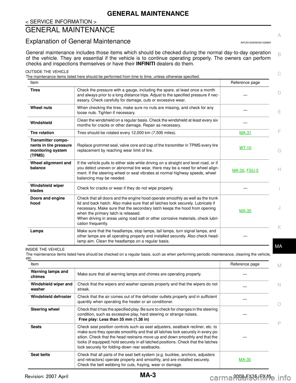
GENERAL MAINTENANCE
Explanation of Gene ral MaintenanceINFOID:0000000001328893
General maintenance includes those items which shoul d be checked during the normal day-to-day operation
of the vehicle. They are essential if the vehicle is to continue operating properly. The owners can perform
checks and inspections themselves or have their INFINITI dealers do them.
OUTSIDE THE VEHICLE
The maintenance items listed here should be performed from time to time, unless otherwise specified.
INSIDE THE VEHICLE The maintenance items listed here should be checked on a regular basis, such as when performing periodic maintenance, cleaning the vehicle,
etc.
Item Reference page
Tires Check the pressure with a gauge, including the spare, at least once a month
and always prior to a long distance trips. Adjust to the specified pressure if nec-
essary. Check carefully for damage, cuts or excessive wear. —
Wheel nuts When checking the tires, make sure no nuts are missing, and check for any
loose nuts. Tighten if necessary. —
Windshield Clean the windshield on a regular basis. Check the windshield at least every six
months for cracks or other damage. Repair as necessary. —
Tire rotation Tires should be rotated every 12,000 km (7,500 miles). MA-31
Transmitter compo-
nents in tire pressure
monitoring system
(TPMS)Replace grommet seal, valve core and cap of the transmitter in TPMS every tire
replacement by reaching wear limit of tire.
WT-10
Wheel alignment and
balanceIf the vehicle pulls to either side while driving on a straight and level road, or if
you detect uneven or abnormal tire wear, there may be a need for wheel align-
ment. If the steering wheel or seat vibrates at normal highway speeds, wheel
balancing may be needed. MA-30
,
FSU-5
Windshield wiper
blades Check for cracks or wear if they do not wipe properly. —
Doors and engine
hood Check that all doors and the engine hood operate smoothly as well as the trunk
lid and back hatch. Also make sure that all latches lock securely. Lubricate if
necessary. Make sure that the secondary latch keeps the hood from opening
when the primary latch is released.
When driving in areas using road salt or other corrosive materials, check lubri-
cation frequently. MA-35
Lamps
Make sure that the headlamps, stop lamps, tail lamps, turn signal lamps, and
other lamps are all operating properly and installed securely. Also check head-
lamp aim. Clean the headlamps on a regular basis. —
Item
Reference page
Warning lamps and
chimes Make sure that all warning lamps and chimes are operating properly. —
Windshield wiper and
washer Check that the wipers and washer operate properly and that the wipers do not
streak.
—
Windshield defroster Check that the air comes out of the defroster outlets properly and in sufficient
quantity when operating the heater or air conditioner. —
Steering wheel Check that it has the specified play. Be sure to check for changes in the steering
condition, such as excessive play, hard steering or strange noises.
Free play: Less than 35 mm (1.38 in) —
Seats Check seat position controls such as seat adjusters, seatback recliner, etc. to
make sure they operate smoothly and that all latches lock securely in every po-
sition. Check that the head restrains move up and down smoothly and that the
locks (if equipped) hold securely in all latched positions. Check that the latches
lock securely for folding-down rear seatbacks. —
Seat belts Check that all parts of the seat belt system (e.g. buckles, anchors, adjusters
and retractors) operate properly and smoothly, and are installed securely.
Check the belt webbing for cuts, fraying, wear or damage. MA-35
3AA93ABC3ACD3AC03ACA3AC03AC63AC53A913A773A893A873A873A8E3A773A983AC73AC93AC03AC3
3A893A873A873A8F3A773A9D3AAF3A8A3A8C3A863A9D3AAF3A8B3A8C
Page 3330 of 3924
ENGINE MAINTENANCE (VQ35DE ENGINE)MA-13
< SERVICE INFORMATION >
C
DE
F
G H
I
J
K
M A
B
MA
N
O P
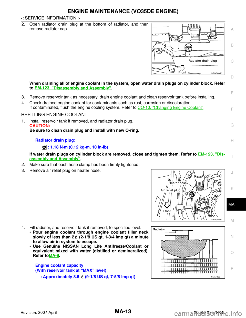
2. Open radiator drain plug at the bottom of radiator, and then
remove radiator cap.
When draining all of engine coolant in the system , open water drain plugs on cylinder block. Refer
to EM-123, "
Disassembly and Assembly".
3. Remove reservoir tank as necessary, drain engine coolant and clean reservoir tank before installing.
4. Check drained engine coolant for contaminants such as rust, corrosion or discoloration. If contaminated, flush the engine cooling system. Refer to CO-10, "
Changing Engine Coolant".
REFILLING ENGINE COOLANT
1. Install reservoir tank if removed, and radiator drain plug.
CAUTION:
Be sure to clean drain plug and install with new O-ring.
If water drain plugs on cylinder block are removed, close and tighten them. Refer to EM-123, "
Dis-
assembly and Assembly".
2. Make sure that each hose clamp has been firmly tightened.
3. Remove air relief plug on heater hose.
4. Fill radiator, and reservoir tank if removed, to specified level. Pour engine coolant through engine coolant filler neck
slowly of less than 2 (2-1/8 US qt, 1-3/4 lmp qt) a minute
to allow air in system to escape.
Use Genuine NISSAN Long Li fe Antifreeze/Coolant or
equivalent mixed with water (dis tilled or demineralized).
Refer to MA-9
.
SBIA0444E
Radiator drain plug:
: 1.18 N·m (0.12 kg-m, 10 in-lb)
SBIA0445E
Engine coolant capacity
(With reservoir tank at “MAX” level): Approximately 8.6 (9-1/8 US qt, 7-5/8 lmp qt)
SMA182B
3AA93ABC3ACD3AC03ACA3AC03AC63AC53A913A773A893A873A873A8E3A773A983AC73AC93AC03AC3
3A893A873A873A8F3A773A9D3AAF3A8A3A8C3A863A9D3AAF3A8B3A8C
Page 3331 of 3924
MA-14
< SERVICE INFORMATION >
ENGINE MAINTENANCE (VQ35DE ENGINE)
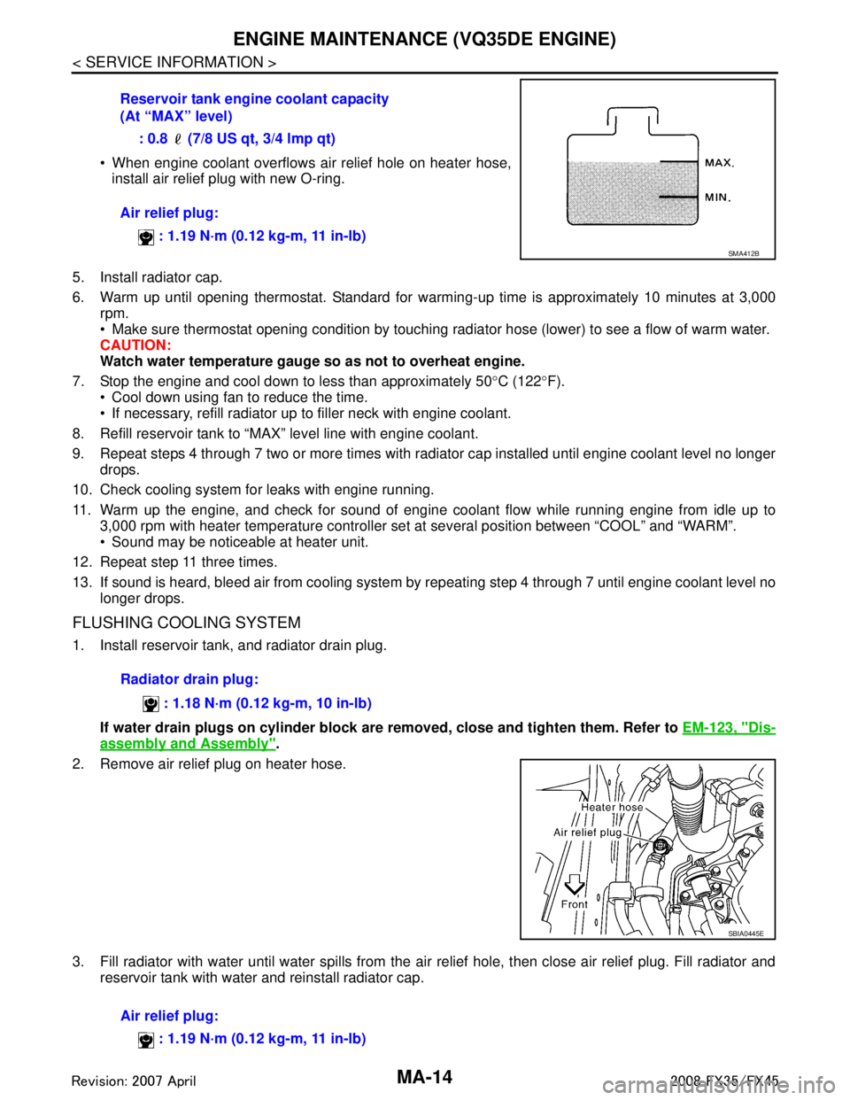
When engine coolant overflows air relief hole on heater hose,install air relief plug with new O-ring.
5. Install radiator cap.
6. Warm up until opening thermostat. Standard for warming- up time is approximately 10 minutes at 3,000
rpm.
Make sure thermostat opening condition by touching radiator hose (lower) to see a flow of warm water.
CAUTION:
Watch water temperature gauge so as not to overheat engine.
7. Stop the engine and cool down to less than approximately 50 °C (122 °F).
Cool down using fan to reduce the time.
If necessary, refill radiator up to filler neck with engine coolant.
8. Refill reservoir tank to “MAX” level line with engine coolant.
9. Repeat steps 4 through 7 two or more times with radiator cap installed until engine coolant level no longer drops.
10. Check cooling system for leaks with engine running.
11. Warm up the engine, and check for sound of engine coolant flow while running engine from idle up to 3,000 rpm with heater temperature controller set at several position between “COOL” and “WARM”.
Sound may be noticeable at heater unit.
12. Repeat step 11 three times.
13. If sound is heard, bleed air from cooling system by repeating step 4 through 7 until engine coolant level no
longer drops.
FLUSHING COOLING SYSTEM
1. Install reservoir tank, and radiator drain plug.
If water drain plugs on cylinder block are removed, close and tighten them. Refer to EM-123, "
Dis-
assembly and Assembly".
2. Remove air relief plug on heater hose.
3. Fill radiator with water until water spills from the ai r relief hole, then close air relief plug. Fill radiator and
reservoir tank with water and reinstall radiator cap. Reservoir tank engine coolant capacity
(At “MAX” level)
: 0.8 (7/8 US qt, 3/4 lmp qt)
Air relief plug: : 1.19 N·m (0.12 kg-m, 11 in-lb)
SMA412B
Radiator drain plug:
: 1.18 N·m (0.12 kg-m, 10 in-lb)
SBIA0445E
Air relief plug: : 1.19 N·m (0.12 kg-m, 11 in-lb)
3AA93ABC3ACD3AC03ACA3AC03AC63AC53A913A773A893A873A873A8E3A773A983AC73AC93AC03AC3
3A893A873A873A8F3A773A9D3AAF3A8A3A8C3A863A9D3AAF3A8B3A8C
Page 3337 of 3924

MA-20
< SERVICE INFORMATION >
ENGINE MAINTENANCE (VK45DE ENGINE)
2. Open radiator drain plug at the bottom of radiator, and thenremove radiator cap.
When draining all of engine cool ant in the system, open water drai n plugs on cylinder block. Refer
to EM-242, "
Disassembly and Assembly".
3. Remove reservoir tank as necessary, and drain engine coolant and clean reservoir tank before installing.
4. Check drained engine coolant for contaminants such as rust, corrosion or discoloration. If contaminated, flush the engine cooling system. Refer to "FLUSHING COOLING SYSTEM".
REFILLING ENGINE COOLANT
1. Install reservoir tank, and radiator drain plug.
CAUTION:
Be sure to clean radiator drain plug and install with new O-ring.
If water drain plugs on cylinder block are removed, close and tighten them. Refer to EM-242, "
Dis-
assembly and Assembly".
2. Make sure that each hose clamp has been firmly tightened.
3. Remove air relief plug on heater hose.
4. Fill thermostat housing and reservoir tank to specified level. Refill engine coolant up to fill er neck of thermostat housing.
Pour engine coolant through engine coolant filler neck slowly of less than 2 (2-1/8 US qt, 1-3/4
Imp qt) a minute to allo w air in system to escape.
Use Genuine NISSAN long Life Antifreeze/Coolant or equivalent mixed with water (distilled or
demineralized). Refer to MA-9
.
SBIA0444E
Radiator drain plug:
: 1.19 N·m (0.12 kg-m, 11 in-lb)
PBIC1530E
Engine coolant capacity
(With reservoir tank at “MAX” level):Approx. 10.0 (10-5/8 US qt, 8-3/4 Imp qt)
3AA93ABC3ACD3AC03ACA3AC03AC63AC53A913A773A893A873A873A8E3A773A983AC73AC93AC03AC3
3A893A873A873A8F3A773A9D3AAF3A8A3A8C3A863A9D3AAF3A8B3A8C
Page 3338 of 3924
ENGINE MAINTENANCE (VK45DE ENGINE)MA-21
< SERVICE INFORMATION >
C
DE
F
G H
I
J
K
M A
B
MA
N
O P
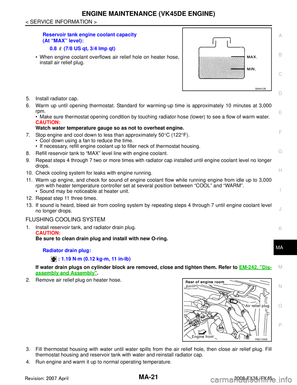
When engine coolant overflows air relief hole on heater hose, install air relief plug.
5. Install radiator cap.
6. Warm up until opening thermostat. Standard for warm ing-up time is approximately 10 minutes at 3,000
rpm.
Make sure thermostat opening condition by touching r adiator hose (lower) to see a flow of warm water.
CAUTION:
Watch water temperature gauge so as not to overheat engine.
7. Stop engine and cool down to less than approximately 50 °C (122 °F).
Cool down using a fan to reduce the time.
If necessary, refill engine coolant up to filler neck of thermostat housing.
8. Refill reservoir tank to “MAX” level line with engine coolant.
9. Repeat steps 4 through 7 two or more times with radiator cap installed until engine coolant level no longer drops.
10. Check cooling system for leaks with engine running.
11. Warm up engine, and check for sound of engine coolant flow while running engine from idle up to 3,000 rpm with heater temperature controller set at several position between “COOL” and “WARM”.
Sound may be noticeable at heater unit.
12. Repeat step 11 three times.
13. If sound is heard, bleed air from cooling system by repeating steps 4 through 7 until engine coolant level
no longer drops.
FLUSHING COOLING SYSTEM
1. Install reservoir tank, and radiator drain plug. CAUTION:
Be sure to clean drain plug and install with new O-ring.
If water drain plugs on cylinder block are removed, close and tighten them. Refer to EM-242, "
Dis-
assembly and Assembly".
2. Remove air relief plug on heater hose.
3. Fill thermostat housing with water until water spills from the air relief hole, then close air relief plug. Fill
thermostat housing and reservoir tank with water and reinstall radiator cap.
4. Run engine and warm it up to normal operating temperature. Reservoir tank engine coolant capacity
(At “MAX” level):
0.8 (7/8 US qt, 3/4 lmp qt)
SMA412B
Radiator drain plug:
: 1.19 N·m (0.12 kg-m, 11 in-lb)
PBIC1530E
3AA93ABC3ACD3AC03ACA3AC03AC63AC53A913A773A893A873A873A8E3A773A983AC73AC93AC03AC3
3A893A873A873A8F3A773A9D3AAF3A8A3A8C3A863A9D3AAF3A8B3A8C
Page 3425 of 3924

HARNESSPG-61
< SERVICE INFORMATION >
C
DE
F
G H
I
J
L
M A
B
PG
N
O P
Code Section Wiring Diagram Name
A/C ATC Air Conditioner
AF1B1 EC Air Fuel Ratio Sensor 1 Bank 1
AF1B2 EC Air Fuel Ratio Sensor 1 Bank 2
AF1HB1 EC Air Fuel Ratio Sensor 1 Heater Bank 1
AF1HB2 EC Air Fuel Ratio Sensor 1 Heater Bank 2
APPS1 EC Accelerator Pedal Position Sensor
APPS2 EC Accelerator Pedal Position Sensor
APPS3 EC Accelerator Pedal Position Sensor
ASC/BS EC Automatic Speed Control Device (ASCD) Brake Switch
ASC/SW EC Automatic Speed Control Device (ASCD) Steering Switch
ASCBOF EC Automatic Speed Control Device (ASCD) Brake Switch
ASCIND EC Automatic Speed Contro l Device (ASCD) Indicator
AT/IND DI A/T Indicator Lamp
AUDIO AV Audio
AUT/DP SE Automatic Drive Positioner
AUTO/L LT Automatic Light System
AWD TF AWD Control System
B/CLOS BL Back Door Closure System
BACK/L LT Back-Up Lamp
BRK/SW EC Brake Switch
CAN AT CAN Communication Line
CAN EC CAN Communication Line
CAN LAN CAN System
CHARGE SC Charging System
CHIME DI Warning Chime
CLOCK DI Clock
COMBSW LT Combination Switch
COMM AV Audio Visual Communication Line
COMPAS DI Compass
COOL/F EC Cooling Fan Control
D/LOCK BL Power Door Lock
DEF GW Rear Window Defogger
DTRL LT Headlamp - With Daytime Light System
ECM/PW EC ECM Power Supply for Back-Up
ECTS EC Engine Coolant Temperature Sensor
ETC1 EC Electric Throttle Control Function
ETC2 EC Electric Throttle Control Motor Relay
ETC3 EC Electric Throttle Control Motor
F/FOG LT Front Fog Lamp
F/PUMP EC Fuel Pump
FTS AT A/T Fluid Temperature Sensor Circuit
FTTS EC Fuel Tank Temperature Sensor
FUELB1 EC Fuel Injection System Function (Bank 1)
FUELB2 EC Fuel Injection System Function (Bank 2)
3AA93ABC3ACD3AC03ACA3AC03AC63AC53A913A773A893A873A873A8E3A773A983AC73AC93AC03AC3
3A893A873A873A8F3A773A9D3AAF3A8A3A8C3A863A9D3AAF3A8B3A8C
Page 3426 of 3924

PG-62
< SERVICE INFORMATION >
HARNESS
H/AIM LT Headlamp Aiming Control System
H/LAMP LT Headlamp
H/PHON AV Hands Free Telephone
HORN WW Horn
HSEAT SE Heated Seat
I/KEY BL Intelligent Key System
I/MIRR GW Inside Mirror (Auto Anti-Dazzling Mirror)
IATS EC Intake Air Temperature Sensor
ICC ACS Intelligent Cruise Control System
ICC/BS EC ICC Brake Switch
ICC/SW EC ICC Steering Switch
ICCBOF EC ICC Brake Switch
IGNSYS EC Ignition System
ILL LT Illumination
INF/D AV Vehicle Information and Integrated Switch System
INJECT EC Injector
IVCB1 EC Intake Valve Timing Control Solenoid Valve Bank 1
IVCB2 EC Intake Valve Timing Control Solenoid Valve Bank 2
IVCSB1 EC Intake Valve Timing Control Position Sensor Bank 1
IVCSB2 EC Intake Valve Timing Control Position Sensor Bank 2
IVTB1 EC Intake Valve Timing Control System (Bank 1)
IVTB2 EC Intake Valve Timing Control System (Bank 2)
KEYLES BL Remote Keyless Entry System
KS EC Knock Sensor
LDW DI Lane Departure Warning System
M/ANT AV Manual Antenna
MAFS EC Mass Air Flow Sensor
MAIN AT Main Power Supply and Ground Circuit
MAIN EC Main Power Supply and Ground Circuit
MES AV Mobile Entertainment System
METER DI Speedometer, Tachometer, Temp. and Fuel Gauges
MIL/DL EC MIL & Data Link Connector
MIRROR GW Power Door Mirror
MMSW AT Manual Mode Switch
NATS BL Nissan Anti-Theft System
NAVI AV Navigation System
NONDTC AT Non-Detective Items
O2H2B1 EC Heated Oxygen Sensor 2 Heater Bank 1
O2H2B2 EC Heated Oxygen Sensor 2 Heater Bank 2
O2S2B1 EC Heated Oxygen Sensor 2 Bank 1
O2S2B2 EC Heated Oxygen Sensor 2 Bank 2
P/SCKT WW Power Socket
PGC/V EC EVAP Canister Purge Volume Control Solenoid Valve
PHASE EC Camshaft Position Sensor (PHASE) Code Section Wiri
ng Diagram Name
3AA93ABC3ACD3AC03ACA3AC03AC63AC53A913A773A893A873A873A8E3A773A983AC73AC93AC03AC3
3A893A873A873A8F3A773A9D3AAF3A8A3A8C3A863A9D3AAF3A8B3A8C
Page 3732 of 3924
FRONT SEATSE-93
< SERVICE INFORMATION >
C
DE
F
G H
J
K L
M A
B
SE
N
O P
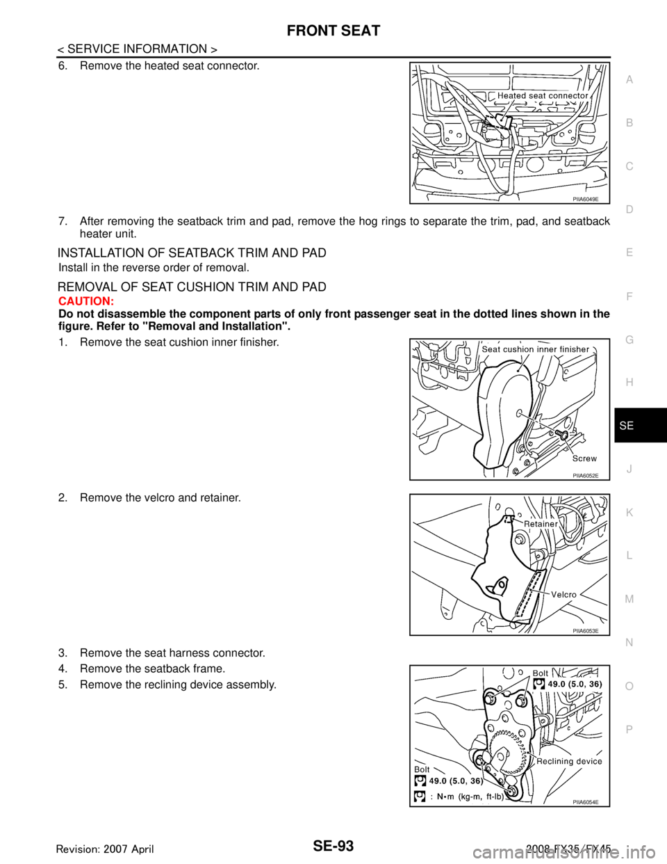
6. Remove the heated seat connector.
7. After removing the seatback trim and pad, remove t he hog rings to separate the trim, pad, and seatback
heater unit.
INSTALLATION OF SEATBACK TRIM AND PAD
Install in the reverse order of removal.
REMOVAL OF SEAT CUSHION TRIM AND PAD
CAUTION:
Do not disassemble the component parts of only fron t passenger seat in the dotted lines shown in the
figure. Refer to "Removal and Installation".
1. Remove the seat cushion inner finisher.
2. Remove the velcro and retainer.
3. Remove the seat harness connector.
4. Remove the seatback frame.
5. Remove the reclining device assembly.
PIIA6049E
PIIA6052E
PIIA6053E
PIIA6054E
3AA93ABC3ACD3AC03ACA3AC03AC63AC53A913A773A893A873A873A8E3A773A983AC73AC93AC03AC3
3A893A873A873A8F3A773A9D3AAF3A8A3A8C3A863A9D3AAF3A8B3A8C