2008 INFINITI FX35 fuse
[x] Cancel search: fusePage 3106 of 3924
LT-4
< SERVICE INFORMATION >
PRECAUTIONS
SERVICE INFORMATION
PRECAUTIONS
Precaution for Supplemental Restraint System (SRS) "AIR BAG" and "SEAT BELT
PRE-TENSIONER"
INFOID:0000000001612924
The Supplemental Restraint System such as “A IR BAG” and “SEAT BELT PRE-TENSIONER”, used along
with a front seat belt, helps to reduce the risk or severi ty of injury to the driver and front passenger for certain
types of collision. This system includes seat belt switch inputs and dual stage front air bag modules. The SRS
system uses the seat belt switches to determine the front air bag deployment, and may only deploy one front
air bag, depending on the severity of a collision and w hether the front occupants are belted or unbelted.
Information necessary to service the system safely is included in the “SUPPLEMENTAL RESTRAINT SYS-
TEM” and “SEAT BELTS” of this Service Manual.
WARNING:
• To avoid rendering the SRS inopera tive, which could increase the risk of personal injury or death in
the event of a collision which would result in air bag inflation, all maintenance must be performed by
an authorized NISS AN/INFINITI dealer.
Improper maintenance, including in correct removal and installation of the SRS, can lead to personal
injury caused by unintent ional activation of the system. For re moval of Spiral Cable and Air Bag
Module, see the “SUPPLEMEN TAL RESTRAINT SYSTEM”.
Do not use electrical test equipmen t on any circuit related to the SRS unless instructed to in this
Service Manual. SRS wiring harnesses can be identi fied by yellow and/or orange harnesses or har-
ness connectors.
General Precaution for Service OperationINFOID:0000000001328264
Never work with wet hands.
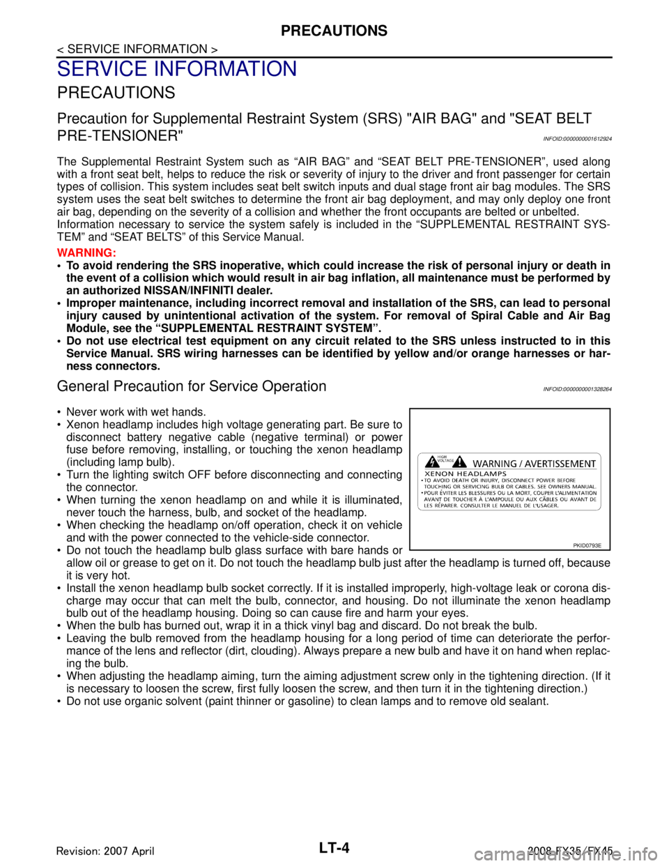
Xenon headlamp includes high voltage generating part. Be sure to disconnect battery negative cable (negative terminal) or power
fuse before removing, installing, or touching the xenon headlamp
(including lamp bulb).
Turn the lighting switch OFF before disconnecting and connecting the connector.
When turning the xenon headlamp on and while it is illuminated, never touch the harness, bulb, and socket of the headlamp.
When checking the headlamp on/off operation, check it on vehicle
and with the power connected to the vehicle-side connector.
Do not touch the headlamp bulb glass surface with bare hands or allow oil or grease to get on it. Do not touch the headl amp bulb just after the headlamp is turned off, because
it is very hot.
Install the xenon headlamp bulb socket co rrectly. If it is installed improperly, high-voltage leak or corona dis-
charge may occur that can melt the bulb, connecto r, and housing. Do not illuminate the xenon headlamp
bulb out of the headlamp housing. Doing so can cause fire and harm your eyes.
When the bulb has burned out, wrap it in a thick vinyl bag and discard. Do not break the bulb.
Leaving the bulb removed from the headlamp housing for a long period of time can deteriorate the perfor- mance of the lens and reflector (dirt, clouding). Al ways prepare a new bulb and have it on hand when replac-
ing the bulb.
When adjusting the headlamp aiming, turn the aiming adjus tment screw only in the tightening direction. (If it
is necessary to loosen the screw, first fully loosen the screw, and then turn it in the tightening direction.)
Do not use organic solvent (paint thinner or gasoline) to clean lamps and to remove old sealant.
PKID0793E
3AA93ABC3ACD3AC03ACA3AC03AC63AC53A913A773A893A873A873A8E3A773A983AC73AC93AC03AC3
3A893A873A873A8F3A773A9D3AAF3A8A3A8C3A863A9D3AAF3A8B3A8C
Page 3107 of 3924
HEADLAMP - XENON TYPE -LT-5
< SERVICE INFORMATION >
C
DE
F
G H
I
J
L
M A
B
LT
N
O P
HEADLAMP - XENON TYPE -
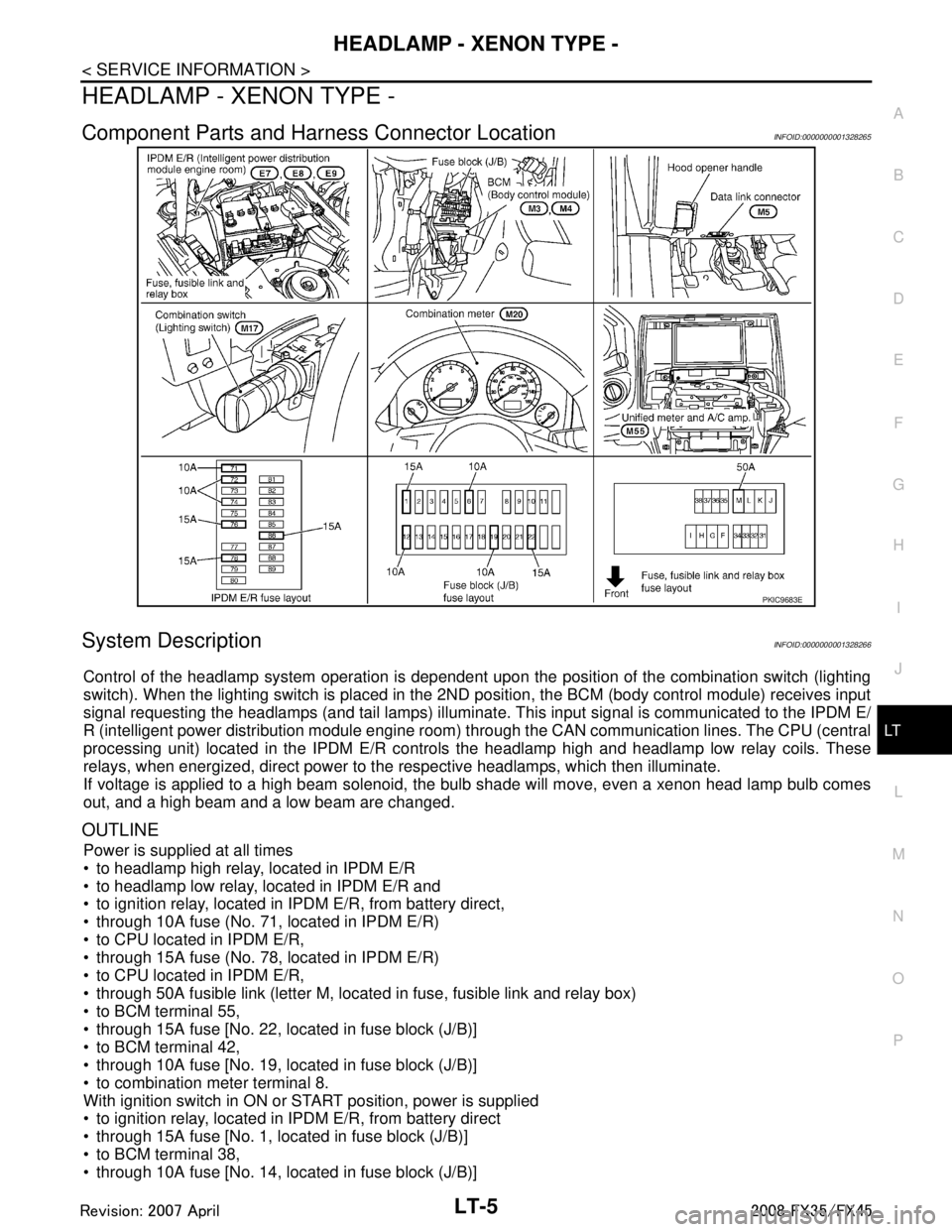
Component Parts and Har ness Connector LocationINFOID:0000000001328265
System DescriptionINFOID:0000000001328266
Control of the headlamp system operation is dependent upon t he position of the combination switch (lighting
switch). When the lighting switch is placed in the 2ND position, the BCM (body control module) receives input
signal requesting the headlamps (and tail lamps) illuminate. This input signal is communicated to the IPDM E/
R (intelligent power distribution module engine room) through the CAN communication lines. The CPU (central
processing unit) located in the IPDM E/R contro ls the headlamp high and headlamp low relay coils. These
relays, when energized, direct power to the respective headlamps, which then illuminate.
If voltage is applied to a high beam solenoid, the bulb shade will move, even a xenon head lamp bulb comes
out, and a high beam and a low beam are changed.
OUTLINE
Power is supplied at all times
to headlamp high relay, located in IPDM E/R
to headlamp low relay, located in IPDM E/R and
to ignition relay, located in IPDM E/R, from battery direct,
through 10A fuse (No. 71, located in IPDM E/R)
to CPU located in IPDM E/R,
through 15A fuse (No. 78, located in IPDM E/R)
to CPU located in IPDM E/R,
through 50A fusible link (letter M, located in fuse, fusible link and relay box)
to BCM terminal 55,
through 15A fuse [No. 22, located in fuse block (J/B)]
to BCM terminal 42,
through 10A fuse [No. 19, located in fuse block (J/B)]
to combination meter terminal 8.
With ignition switch in ON or START position, power is supplied
to ignition relay, located in IPDM E/R, from battery direct
through 15A fuse [No. 1, located in fuse block (J/B)]
to BCM terminal 38,
through 10A fuse [No. 14, located in fuse block (J/B)]
PKIC9683E
3AA93ABC3ACD3AC03ACA3AC03AC63AC53A913A773A893A873A873A8E3A773A983AC73AC93AC03AC3
3A893A873A873A8F3A773A9D3AAF3A8A3A8C3A863A9D3AAF3A8B3A8C
Page 3108 of 3924

LT-6
< SERVICE INFORMATION >
HEADLAMP - XENON TYPE -
to combination meter terminal 7.
With ignition switch in ACC or ON position, power is supplied
through 10A fuse [No. 6, located in fuse block (J/B)]
to BCM terminal 11.
Ground is supplied
to BCM terminals 49 and 52
through grounds M35, M45 and M85,
to IPDM E/R terminals 38 and 60
through grounds E21, E50 and E51,
to combination meter terminals 5, 6 and 15
through grounds M35, M45 and M85.
HEADLAMP OPERATION
Low Beam Operation
With the lighting switch in the 2ND position, the BCM receives input signal requesting the headlamps to illumi-
nate. This input signal is communicated to the IP DM E/R through the CAN communication lines. The CPU
located in the IPDM E/R controls the headlamp lo w relay coil, which when energized, directs power
through 15A fuse (No. 76, located in IPDM E/R)
through IPDM E/R terminal 20
to front combination lamp RH terminal 6,
through 15A fuse (No. 86, located in IPDM E/R)
through IPDM E/R terminal 30
to front combination lamp LH terminal 6.
Ground is supplied
to front combination lamp RH and LH terminals 7
through grounds E21, E50 and E51,
With power and ground supplied, low beam headlamps illuminate.
High Beam Operation/Flash-to-Pass Operation
With the lighting switch in the 2ND position and placed in the HIGH or PASS position, the BCM receives input
signal requesting the headlamp high beams to illuminate. Th is input signal is communicated to the IPDM E/R
through the CAN communication lines. The CPU located in the IPDM E/R controls the headlamp high relay
coil and low relay coil, which when energized, directs power
through 15A fuse (No. 76, located in IPDM E/R)
through IPDM E/R terminal 20
to front combination lamp RH terminal 6,
through 15A fuse (No. 86, located in IPDM E/R)
through IPDM E/R terminal 30
to front combination lamp LH terminal 6,
through 10A fuse (No. 72, located in IPDM E/R)
through IPDM E/R terminal 27
to front combination lamp RH terminal 5,
through 10A fuse (No. 74, located in IPDM E/R)
through IPDM E/R terminal 28
to front combination lamp LH terminal 5.
Ground is supplied
to front combination lamp RH and LH terminals 7
through grounds E21, E50 and E51,
With power and ground supplied, the high beam headlamps illuminate.
If voltage is applied to a high beam solenoid, the bulb shade will move, even a xenon head lamp bulb comes
out, and a high beam and a low beam are changed.
The unified meter and A/C amp. that received the hi gh beam request signal by BCM through the CAN commu-
nication makes a high beam indicator lamp turn on in combination meter.
COMBINATION SWITCH READING FUNCTION
Refer to BCS-4, "System Description".
EXTERIOR LAMP BATTERY SAVER CONTROL
When the combination switch (lighting switch) is in the 2ND position (ON), and the ignition switch is turned
from ON or ACC to OFF, the battery saver control function is activated.
Under this condition, the headlamps remain illumi nated for 5 minutes, then the headlamps are turned OFF.
3AA93ABC3ACD3AC03ACA3AC03AC63AC53A913A773A893A873A873A8E3A773A983AC73AC93AC03AC3
3A893A873A873A8F3A773A9D3AAF3A8A3A8C3A863A9D3AAF3A8B3A8C
Page 3117 of 3924
HEADLAMP - XENON TYPE -LT-15
< SERVICE INFORMATION >
C
DE
F
G H
I
J
L
M A
B
LT
N
O P
2. Understand operation description and function description. Refer to LT- 5 , "System Description".
3. Perform Preliminary Check. Refer to LT-15, "
Preliminary Check".
4. Check symptom and repair or replace the cause of malfunction.
5. Does headlamp operate normally? If YES, GO TO 6. If NO, GO TO 4.
6. INSPECTION END
Preliminary CheckINFOID:0000000001328274
CHECK POWER SUPPLY AND GROUND CIRCUIT
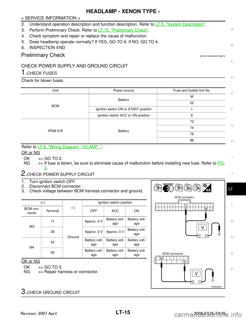
1.CHECK FUSES
Check for blown fuses.
Refer to LT- 9 , "
Wiring Diagram - H/LAMP -".
OK or NG
OK >> GO TO 2.
NG >> If fuse is blown, be sure to eliminate caus e of malfunction before installing new fuse. Refer to PG-
3.
2.CHECK POWER SUPPLY CIRCUIT
1. Turn ignition switch OFF.
2. Disconnect BCM connector.
3. Check voltage between BCM harness connector and ground.
OK or NG
OK >> GO TO 3.
NG >> Repair harness or connector.
3.CHECK GROUND CIRCUIT
Unit Power source Fuse and fusible link No.
BCM Battery
M
22
Ignition switch ON or START position 1 Ignition switch ACC or ON position 6
IPDM E/R Battery 72
74
76
86
(+)
(-)Ignition switch position
BCM con- nector Terminal OFF ACC ON
M3 11
Ground Approx. 0 V
Battery volt-
age Battery volt-
age
38 Approx. 0 V Approx. 0 V Battery volt-
age
M4 42
Battery volt-
age Battery volt-
age Battery volt-
age
55 Battery volt-
age Battery volt-
age Battery volt-
age
PKIA5204E
3AA93ABC3ACD3AC03ACA3AC03AC63AC53A913A773A893A873A873A8E3A773A983AC73AC93AC03AC3
3A893A873A873A8F3A773A9D3AAF3A8A3A8C3A863A9D3AAF3A8B3A8C
Page 3128 of 3924
LT-26
< SERVICE INFORMATION >
HEADLAMP - XENON TYPE -
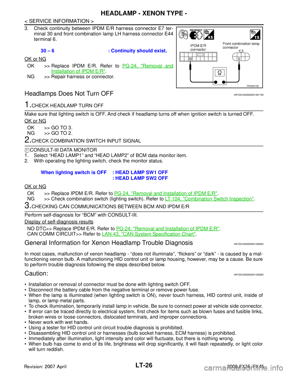
3. Check continuity between IPDM E/R harness connector E7 ter-minal 30 and front combination lamp LH harness connector E44
terminal 6.
OK or NG
OK >> Replace IPDM E/R. Refer to PG-24, "Removal and
Installation of IPDM E/R".
NG >> Repair harness or connector.
Headlamps Does Not Turn OFFINFOID:0000000001381748
1.CHECK HEADLAMP TURN OFF
Make sure that lighting switch is OFF. And check if headlamp turns off when ignition switch is turned OFF.
OK or NG
OK >> GO TO 3.
NG >> GO TO 2.
2.CHECK COMBINATION SWITCH INPUT SIGNAL
CONSULT-III DATA MONITOR
1. Select “HEAD LAMP1” and “HEAD LAMP2” of BCM data monitor item.
2. With operating the lighting switch, check the monitor status.
OK or NG
OK >> Replace IPDM E/R. Refer to PG-24, "Removal and Installation of IPDM E/R".
NG >> Check combination switch (lighting switch). Refer to LT-104, "
Combination Switch Inspection".
3.CHECKING CAN COMMUNICATIONS BETWEEN BCM AND IPDM E/R
Perform self-diagnosis for “BCM” with CONSULT-III.
Display of self-diagnosis results
NO DTC>> Replace IPDM E/R. Refer to PG-24, "Removal and Installation of IPDM E/R".
CAN COMM CIRCUIT>> Refer to LAN-43, "
CAN System Specification Chart".
General Information for Xenon Headlamp Trouble DiagnosisINFOID:0000000001328284
In most cases, malfunction of xenon headlamp - “does not ill uminate”, “flickers” or “dark” - is caused by a mal-
functioning xenon bulb. A malfunctioning HID control unit or lamp housing, however, may be a cause. Be sure
to perform trouble diagnosis following the steps described below.
Caution:INFOID:0000000001328285
Installation or removal of connector must be done with lighting switch OFF.
Disconnect the battery cable from the negative terminal or remove power fuse.
When the lamp is illuminated (when lighting switch is ON), never touch harness, HID control unit, inside of
lamp, or lamp metal parts.
To check illumination, temporarily install lamp in vehicle. Be sure to connect power at vehicle side connector.
If error can be traced directly to electrical system, fi rst check for items such as blown fuses and fusible links,
broken wires or loose connectors, dislocated terminals, and improper connections.
Never work with wet hands.
Using a tester for HID control unit circuit trouble diagnosis is prohibited.
Disassembling HID control unit or harnesses ( bulb socket harness, ECM harness) is prohibited.
Immediately after illumination, light intensity and color will fluctuate, but there is nothing wrong.
When bulb has come to end of its life, brightness will dr op significantly, it will flash repeatedly, or light color
will turn reddish. 30 – 6 : Continuity should exist.
PKIA5213E
When lighting switch is OFF : HEAD LAMP SW1 OFF
: HEAD LAMP SW2 OFF
3AA93ABC3ACD3AC03ACA3AC03AC63AC53A913A773A893A873A873A8E3A773A983AC73AC93AC03AC3
3A893A873A873A8F3A773A9D3AAF3A8A3A8C3A863A9D3AAF3A8B3A8C
Page 3131 of 3924
HEADLAMP - XENON TYPE -LT-29
< SERVICE INFORMATION >
C
DE
F
G H
I
J
L
M A
B
LT
N
O P
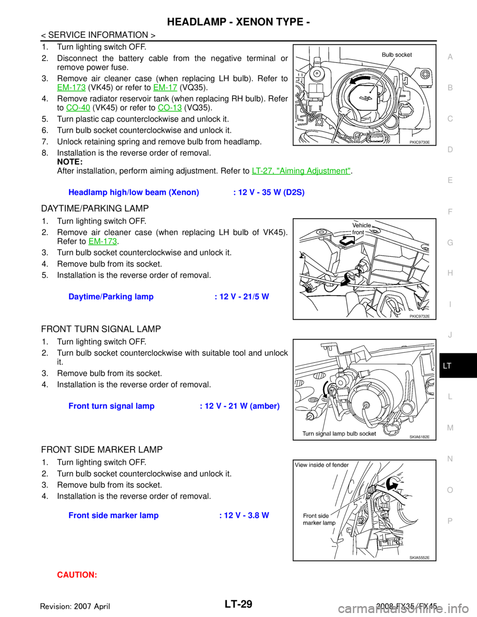
1. Turn lighting switch OFF.
2. Disconnect the battery cable from the negative terminal or remove power fuse.
3. Remove air cleaner case (when replacing LH bulb). Refer to EM-173
(VK45) or refer to EM-17 (VQ35).
4. Remove radiator reservoir tank (when replacing RH bulb). Refer to CO-40
(VK45) or refer to CO-13 (VQ35).
5. Turn plastic cap counterclockwise and unlock it.
6. Turn bulb socket counterclockwise and unlock it.
7. Unlock retaining spring and remove bulb from headlamp.
8. Installation is the reverse order of removal. NOTE:
After installation, perform aiming adjustment. Refer to LT-27, "
Aiming Adjustment".
DAYTIME/PARKING LAMP
1. Turn lighting switch OFF.
2. Remove air cleaner case (when replacing LH bulb of VK45).
Refer to EM-173
.
3. Turn bulb socket counterclockwise and unlock it.
4. Remove bulb from its socket.
5. Installation is the reverse order of removal.
FRONT TURN SIGNAL LAMP
1. Turn lighting switch OFF.
2. Turn bulb socket counterclockwise with suitable tool and unlock it.
3. Remove bulb from its socket.
4. Installation is the reverse order of removal.
FRONT SIDE MARKER LAMP
1. Turn lighting switch OFF.
2. Turn bulb socket counterclockwise and unlock it.
3. Remove bulb from its socket.
4. Installation is the reverse order of removal.
CAUTION:Headlamp high/low beam (Xenon) : 12 V - 35 W (D2S)
PKIC9730E
Daytime/Parking lamp : 12 V - 21/5 W
PKIC9732E
Front turn signal lamp : 12 V - 21 W (amber)
SKIA6182E
Front side marker lamp : 12 V - 3.8 W
SKIA5552E
3AA93ABC3ACD3AC03ACA3AC03AC63AC53A913A773A893A873A873A8E3A773A983AC73AC93AC03AC3
3A893A873A873A8F3A773A9D3AAF3A8A3A8C3A863A9D3AAF3A8B3A8C
Page 3132 of 3924
LT-30
< SERVICE INFORMATION >
HEADLAMP - XENON TYPE -
After installing bulb, be sure to install plastic cap and bulb socket securely to insure watertight-
ness.
Removal and InstallationINFOID:0000000001328289
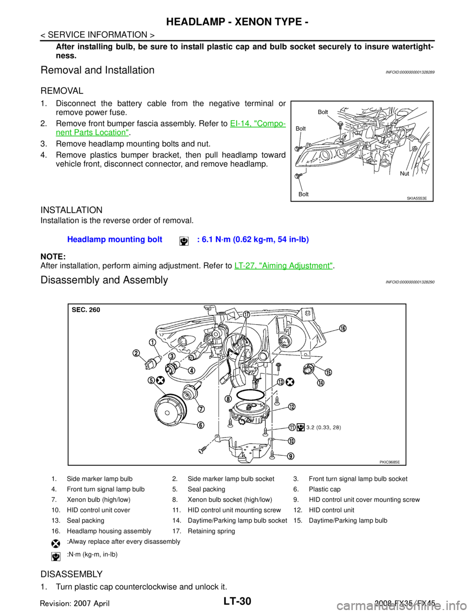
REMOVAL
1. Disconnect the battery cable from the negative terminal or remove power fuse.
2. Remove front bumper fascia assembly. Refer to EI-14, "
Compo-
nent Parts Location".
3. Remove headlamp mounting bolts and nut.
4. Remove plastics bumper bracket, then pull headlamp toward vehicle front, disconnect connector, and remove headlamp.
INSTALLATION
Installation is the reverse order of removal.
NOTE:
After installation, perform aiming adjustment. Refer to LT-27, "
Aiming Adjustment".
Disassembly and AssemblyINFOID:0000000001328290
DISASSEMBLY
1. Turn plastic cap counterclockwise and unlock it.
SKIA5553E
Headlamp mounting bolt : 6.1 N·m (0.62 kg-m, 54 in-lb)
1. Side marker lamp bulb 2. Side marker lamp bulb socket 3. Front turn signal lamp bulb socket
4. Front turn signal lamp bulb 5. Seal packing 6. Plastic cap
7. Xenon bulb (high/low) 8. Xenon bulb socket (high/low) 9. HID control unit cover mounting screw
10. HID control unit cover 11. HID control unit mounting screw 12. HID control unit
13. Seal packing 14. Daytime/Parking lamp bulb socket 15. Daytime/Parking lamp bulb
16. Headlamp housing assembly 17. Retaining spring
:Alway replace after every disassembly
:N·m (kg-m, in-lb)
PKIC9685E
3AA93ABC3ACD3AC03ACA3AC03AC63AC53A913A773A893A873A873A8E3A773A983AC73AC93AC03AC3
3A893A873A873A8F3A773A9D3AAF3A8A3A8C3A863A9D3AAF3A8B3A8C
Page 3134 of 3924
LT-32
< SERVICE INFORMATION >
DAYTIME LIGHT SYSTEM
DAYTIME LIGHT SYSTEM
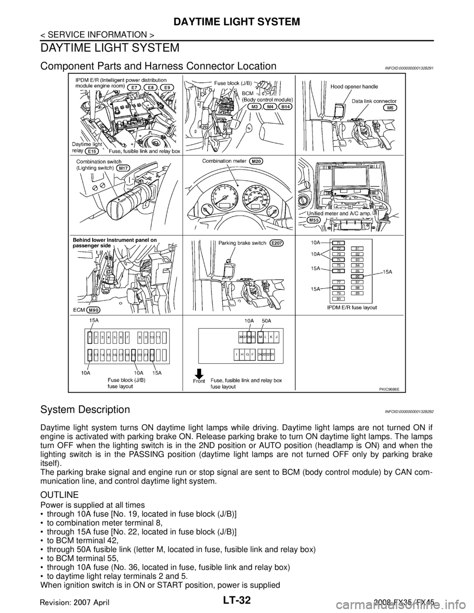
Component Parts and Harness Connector LocationINFOID:0000000001328291
System DescriptionINFOID:0000000001328292
Daytime light system turns ON daytime light lamps while driving. Daytime light lamps are not turned ON if
engine is activated with parking brake ON. Release parki ng brake to turn ON daytime light lamps. The lamps
turn OFF when the lighting switch is in the 2ND pos ition or AUTO position (headlamp is ON) and when the
lighting switch is in the PASSING position (daytime light lamps are not turned OFF only by parking brake
itself).
The parking brake signal and engine run or stop signal ar e sent to BCM (body control module) by CAN com-
munication line, and control daytime light system.
OUTLINE
Power is supplied at all times
through 10A fuse [No. 19, located in fuse block (J/B)]
to combination meter terminal 8,
through 15A fuse [No. 22, located in fuse block (J/B)]
to BCM terminal 42,
through 50A fusible link (letter M, located in fuse, fusible link and relay box)
to BCM terminal 55,
through 10A fuse (No. 36, located in fuse, fusible link and relay box)
to daytime light relay terminals 2 and 5.
When ignition switch is in ON or START position, power is supplied
PKIC9686E
3AA93ABC3ACD3AC03ACA3AC03AC63AC53A913A773A893A873A873A8E3A773A983AC73AC93AC03AC3
3A893A873A873A8F3A773A9D3AAF3A8A3A8C3A863A9D3AAF3A8B3A8C