2008 INFINITI FX35 spare tire
[x] Cancel search: spare tirePage 2862 of 3924

FSU-18
< SERVICE INFORMATION >
SERVICE DATA AND SPECIFICATIONS (SDS)
*: Fuel, engine coolant and lubricant are oil full. Spare tire, jack, hand tools and mats are in designated positions.Front (Hf)
835 mm
(32.87 in) 834 mm
(32.83 in) 834 mm
(32.83 in) 833 mm
(32.80 in) 832 mm
(32.76 in) 834 mm
(32.83 in) 833 mm
(32.80 in) 832 mm
(32.76 in)
Rear (Hr) 822 mm
(32.36 in) 821 mm
(32.32 in) 829 mm
(32.64 in) 827 mm
(32.56 in) 825 mm
(32.48 in) 827 mm
(32.56 in) 826 mm
(32.52 in) 823 mm
(32.40 in)
3AA93ABC3ACD3AC03ACA3AC03AC63AC53A913A773A893A873A873A8E3A773A983AC73AC93AC03AC3
3A893A873A873A8F3A773A9D3AAF3A8A3A8C3A863A9D3AAF3A8B3A8C
Page 2909 of 3924
IDENTIFICATION INFORMATIONGI-47
< SERVICE INFORMATION >
C
DE
F
G H
I
J
K L
M B
GI
N
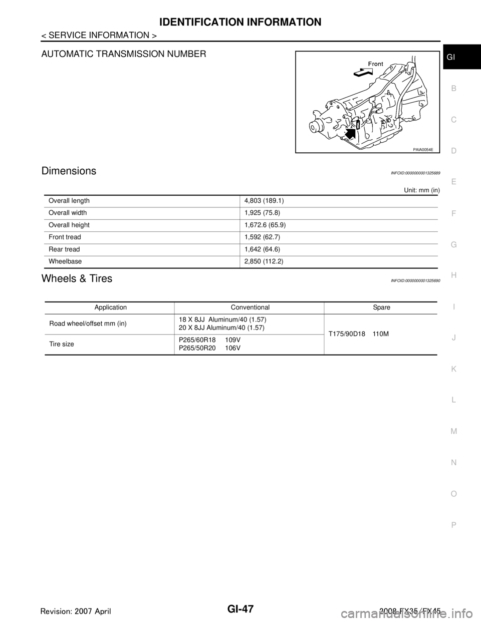
O PAUTOMATIC TRANSMISSION NUMBER
DimensionsINFOID:0000000001325689
Unit: mm (in)
Wheels & TiresINFOID:0000000001325690
PAIA0054E
Overall length 4,803 (189.1)
Overall width 1,925 (75.8)
Overall height 1,672.6 (65.9)
Front tread 1,592 (62.7)
Rear tread 1,642 (64.6)
Wheelbase 2,850 (112.2)
Application Conventional Spare
Road wheel/offset mm (in) 18 X 8JJ Aluminum/40 (1.57)
20 X 8JJ Aluminum/40 (1.57)
T175/90D18 110M
Tire size P265/60R18 109V
P265/50R20 106V
3AA93ABC3ACD3AC03ACA3AC03AC63AC53A913A773A893A873A873A8E3A773A983AC73AC93AC03AC3
3A893A873A873A8F3A773A9D3AAF3A8A3A8C3A863A9D3AAF3A8B3A8C
Page 3177 of 3924
FRONT FOG LAMPLT-75
< SERVICE INFORMATION >
C
DE
F
G H
I
J
L
M A
B
LT
N
O P
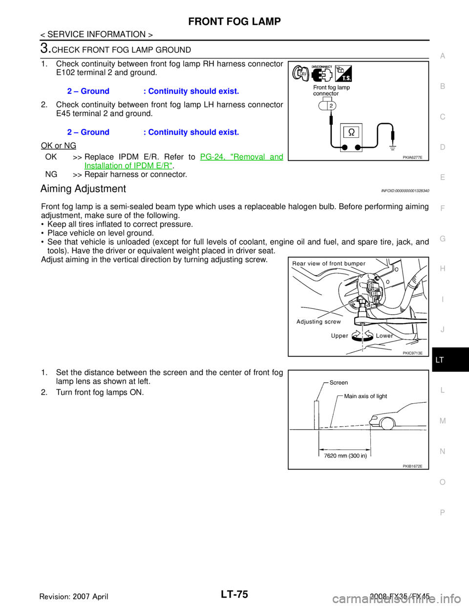
3.CHECK FRONT FOG LAMP GROUND
1. Check continuity between front fog lamp RH harness connector E102 terminal 2 and ground.
2. Check continuity between front fog lamp LH harness connector E45 terminal 2 and ground.
OK or NG
OK >> Replace IPDM E/R. Refer to PG-24, "Removal and
Installation of IPDM E/R".
NG >> Repair harness or connector.
Aiming AdjustmentINFOID:0000000001328340
Front fog lamp is a semi-sealed beam type which uses a replaceable halogen bulb. Before performing aiming
adjustment, make sure of the following.
Keep all tires inflated to correct pressure.
Place vehicle on level ground.
See that vehicle is unloaded (except for full levels of coolant, engine oil and fuel, and spare tire, jack, and tools). Have the driver or equivalent weight placed in driver seat.
Adjust aiming in the vertical direction by turning adjusting screw.
1. Set the distance between the scr een and the center of front fog
lamp lens as shown at left.
2. Turn front fog lamps ON. 2 – Ground : Continuity should exist.
2 – Ground : Continuity should exist.
PKIA6277E
PKIC9713E
PKIB1672E
3AA93ABC3ACD3AC03ACA3AC03AC63AC53A913A773A893A873A873A8E3A773A983AC73AC93AC03AC3
3A893A873A873A8F3A773A9D3AAF3A8A3A8C3A863A9D3AAF3A8B3A8C
Page 3320 of 3924
GENERAL MAINTENANCEMA-3
< SERVICE INFORMATION >
C
DE
F
G H
I
J
K
M A
B
MA
N
O P
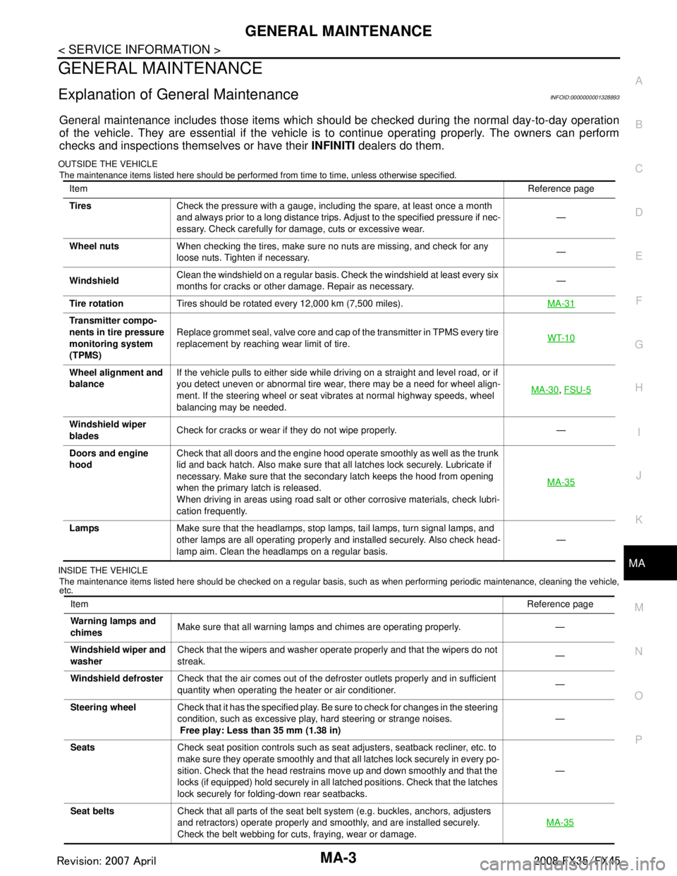
GENERAL MAINTENANCE
Explanation of Gene ral MaintenanceINFOID:0000000001328893
General maintenance includes those items which shoul d be checked during the normal day-to-day operation
of the vehicle. They are essential if the vehicle is to continue operating properly. The owners can perform
checks and inspections themselves or have their INFINITI dealers do them.
OUTSIDE THE VEHICLE
The maintenance items listed here should be performed from time to time, unless otherwise specified.
INSIDE THE VEHICLE The maintenance items listed here should be checked on a regular basis, such as when performing periodic maintenance, cleaning the vehicle,
etc.
Item Reference page
Tires Check the pressure with a gauge, including the spare, at least once a month
and always prior to a long distance trips. Adjust to the specified pressure if nec-
essary. Check carefully for damage, cuts or excessive wear. —
Wheel nuts When checking the tires, make sure no nuts are missing, and check for any
loose nuts. Tighten if necessary. —
Windshield Clean the windshield on a regular basis. Check the windshield at least every six
months for cracks or other damage. Repair as necessary. —
Tire rotation Tires should be rotated every 12,000 km (7,500 miles). MA-31
Transmitter compo-
nents in tire pressure
monitoring system
(TPMS)Replace grommet seal, valve core and cap of the transmitter in TPMS every tire
replacement by reaching wear limit of tire.
WT-10
Wheel alignment and
balanceIf the vehicle pulls to either side while driving on a straight and level road, or if
you detect uneven or abnormal tire wear, there may be a need for wheel align-
ment. If the steering wheel or seat vibrates at normal highway speeds, wheel
balancing may be needed. MA-30
,
FSU-5
Windshield wiper
blades Check for cracks or wear if they do not wipe properly. —
Doors and engine
hood Check that all doors and the engine hood operate smoothly as well as the trunk
lid and back hatch. Also make sure that all latches lock securely. Lubricate if
necessary. Make sure that the secondary latch keeps the hood from opening
when the primary latch is released.
When driving in areas using road salt or other corrosive materials, check lubri-
cation frequently. MA-35
Lamps
Make sure that the headlamps, stop lamps, tail lamps, turn signal lamps, and
other lamps are all operating properly and installed securely. Also check head-
lamp aim. Clean the headlamps on a regular basis. —
Item
Reference page
Warning lamps and
chimes Make sure that all warning lamps and chimes are operating properly. —
Windshield wiper and
washer Check that the wipers and washer operate properly and that the wipers do not
streak.
—
Windshield defroster Check that the air comes out of the defroster outlets properly and in sufficient
quantity when operating the heater or air conditioner. —
Steering wheel Check that it has the specified play. Be sure to check for changes in the steering
condition, such as excessive play, hard steering or strange noises.
Free play: Less than 35 mm (1.38 in) —
Seats Check seat position controls such as seat adjusters, seatback recliner, etc. to
make sure they operate smoothly and that all latches lock securely in every po-
sition. Check that the head restrains move up and down smoothly and that the
locks (if equipped) hold securely in all latched positions. Check that the latches
lock securely for folding-down rear seatbacks. —
Seat belts Check that all parts of the seat belt system (e.g. buckles, anchors, adjusters
and retractors) operate properly and smoothly, and are installed securely.
Check the belt webbing for cuts, fraying, wear or damage. MA-35
3AA93ABC3ACD3AC03ACA3AC03AC63AC53A913A773A893A873A873A8E3A773A983AC73AC93AC03AC3
3A893A873A873A8F3A773A9D3AAF3A8A3A8C3A863A9D3AAF3A8B3A8C
Page 3348 of 3924
CHASSIS AND BODY MAINTENANCEMA-31
< SERVICE INFORMATION >
C
DE
F
G H
I
J
K
M A
B
MA
N
O P
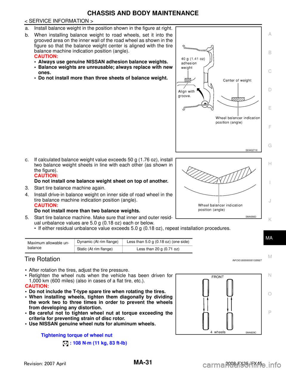
a. Install balance weight in the position shown in the figure at right.
b. When installing balance weight to road wheels, set it into the grooved area on the inner wall of the road wheel as shown in the
figure so that the balance weight center is aligned with the tire
balance machine indication position (angle).
CAUTION:
Always use genuine NISSAN adhesion balance weights.
Balance weights are unreusable; always replace with newones.
Do not install more than three sheets of balance weight.
c. If calculated balance weight value exceeds 50 g (1.76 oz), install two balance weight sheets in line with each other (as shown in
the figure).
CAUTION:
Do not install one balance weig ht sheet on top of another.
3. Start tire balance machine again.
4. Install drive-in balance weight on inner side of road wheel in the tire balance machine indication position (angle).
CAUTION:
Do not install more than two balance weights.
5. Start tire balance machine. Make sure that inner and outer resid- ual unbalance values are 5.0 g (0.18 oz) each or below.
If either residual unbalance value exceeds 5.0 g (0.18 oz), repeat installation procedures.
Tire RotationINFOID:0000000001328927
After rotation the tires, adjust the tire pressure.
Retighten the wheel nuts when the vehicle has been driven for
1,000 km (600 miles) (also in cases of a flat tire, etc.).
CAUTION:
Do not include the T-type spare tire when rotating the tires.
When installing wheels, tighte n them diagonally by dividing
the work two to three times in order to prevent the wheels
from developing any distortion.
Be careful not to tighten wh eel nut at torque exceeding the
criteria for preventing strain of disc rotor.
Use NISSAN genuine wheel nu ts for aluminum wheels.
SEIA0271E
Maximum allowable un-
balanceDynamic (At rim flange) Less than 5.0 g (0.18 oz) (one side)
Static (At rim flange) Less than 20 g (0.71 oz)
SMA056D
Tightening torque of wheel nut
: 108 N·m (11 kg, 83 ft-lb)SMA829C
3AA93ABC3ACD3AC03ACA3AC03AC63AC53A913A773A893A873A873A8E3A773A983AC73AC93AC03AC3
3A893A873A873A8F3A773A9D3AAF3A8A3A8C3A863A9D3AAF3A8B3A8C
Page 3583 of 3924

RSU-2
< SERVICE INFORMATION >
PRECAUTIONS
SERVICE INFORMATION
PRECAUTIONS
CautionsINFOID:0000000001327548
• When installing rubber bushings, final tightening must be carried out under unladen conditions with tires on
level ground. Oil will shorten the life of rubber bushings. Be sure to wipe off any spilled oil.
Unladen conditions means that fuel, engine coolant and lubricant are full. Spare tire, jack, hand tools and
mats are in designated positions.
After servicing suspension parts, be sure to check wheel alignment.
Caulking nuts are not reusable. Always use new ones w hen installing. Since new caulking nuts are pre-oiled,
tighten as they are.
3AA93ABC3ACD3AC03ACA3AC03AC63AC53A913A773A893A873A873A8E3A773A983AC73AC93AC03AC3
3A893A873A873A8F3A773A9D3AAF3A8A3A8C3A863A9D3AAF3A8B3A8C
Page 3586 of 3924
REAR SUSPENSION ASSEMBLYRSU-5
< SERVICE INFORMATION >
C
DF
G H
I
J
K L
M A
B
RSU
N
O P
REAR SUSPENSION ASSEMBLY
On-Vehicle Inspection and ServiceINFOID:0000000001327552
Make sure the mounting conditions (looseness, ba ck lash) of each component and component status (wear,
damage) are normal.
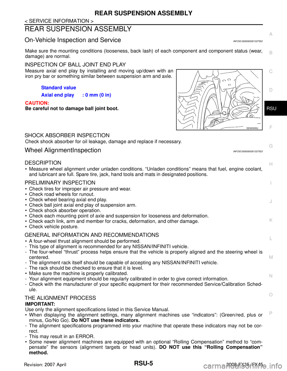
INSPECTION OF BALL JOINT END PLAY
Measure axial end play by installing and moving up/down with an
iron pry bar or something similar between suspension arm and axle.
CAUTION:
Be careful not to damage ball joint boot.
SHOCK ABSORBER INSPECTION
Check shock absorber for oil leakage, damage and replace if necessary.
Wheel AlignmentInspectionINFOID:0000000001327553
DESCRIPTION
Measure wheel alignment under unladen conditions. “U nladen conditions” means that fuel, engine coolant,
and lubricant are full. Spare tire, jack, hand tools and mats in designated positions.
PRELIMINARY INSPECTION
Check tires for improper air pressure and wear.
Check road wheels for runout.
Check wheel bearing axial end play.
Check ball joint axial end play of suspension arm.
Check shock absorber operation.
Check each mounting point of axle and suspension for looseness and deformation.
Check each link, arm and member for cracks, deformation, and other damage.
Check vehicle posture.
GENERAL INFORMATION AND RECOMMENDATIONS
A four-wheel thrust alignment should be performed.
- This type of alignment is recomm ended for any NISSAN/INFINITI vehicle.
- The four-wheel “thrust” process helps ensure that t he vehicle is properly aligned and the steering wheel is
centered.
- The alignment rack itself should be capable of accepting any NISSAN/INFINITI vehicle.
- The rack should be checked to ensure that it is level.
Make sure the machine is properly calibrated.
- Your alignment equipment should be regularly ca librated in order to give correct information.
- Check with the manufacturer of your specific equi pment for their recommended Service/Calibration Sched-
ule.
THE ALIGNMENT PROCESS
IMPORTANT:
Use only the alignment specificati ons listed in this Service Manual.
When displaying the alignment settings, many alignment machines use “indicators”: (Green/red, plus or
minus, Go/No Go). Do NOT use these indicators.
- The alignment specifications programmed into your machine that operate these indicators may not be cor-
rect.
- This may result in an ERROR.
Some newer alignment machines are equipped with an optional “Rolling Compensation” method to “com-
pensate” the sensors (alignment targets or head units). DO NOT use this “Rolling Compensation”
method. Standard value
Axial end play : 0 mm (0 in)
SEIA0245J
3AA93ABC3ACD3AC03ACA3AC03AC63AC53A913A773A893A873A873A8E3A773A983AC73AC93AC03AC3
3A893A873A873A8F3A773A9D3AAF3A8A3A8C3A863A9D3AAF3A8B3A8C
Page 3599 of 3924
RSU-18
< SERVICE INFORMATION >
SERVICE DATA AND SPECIFICATIONS (SDS)
SERVICE DATA AND SPECIFICATIONS (SDS)
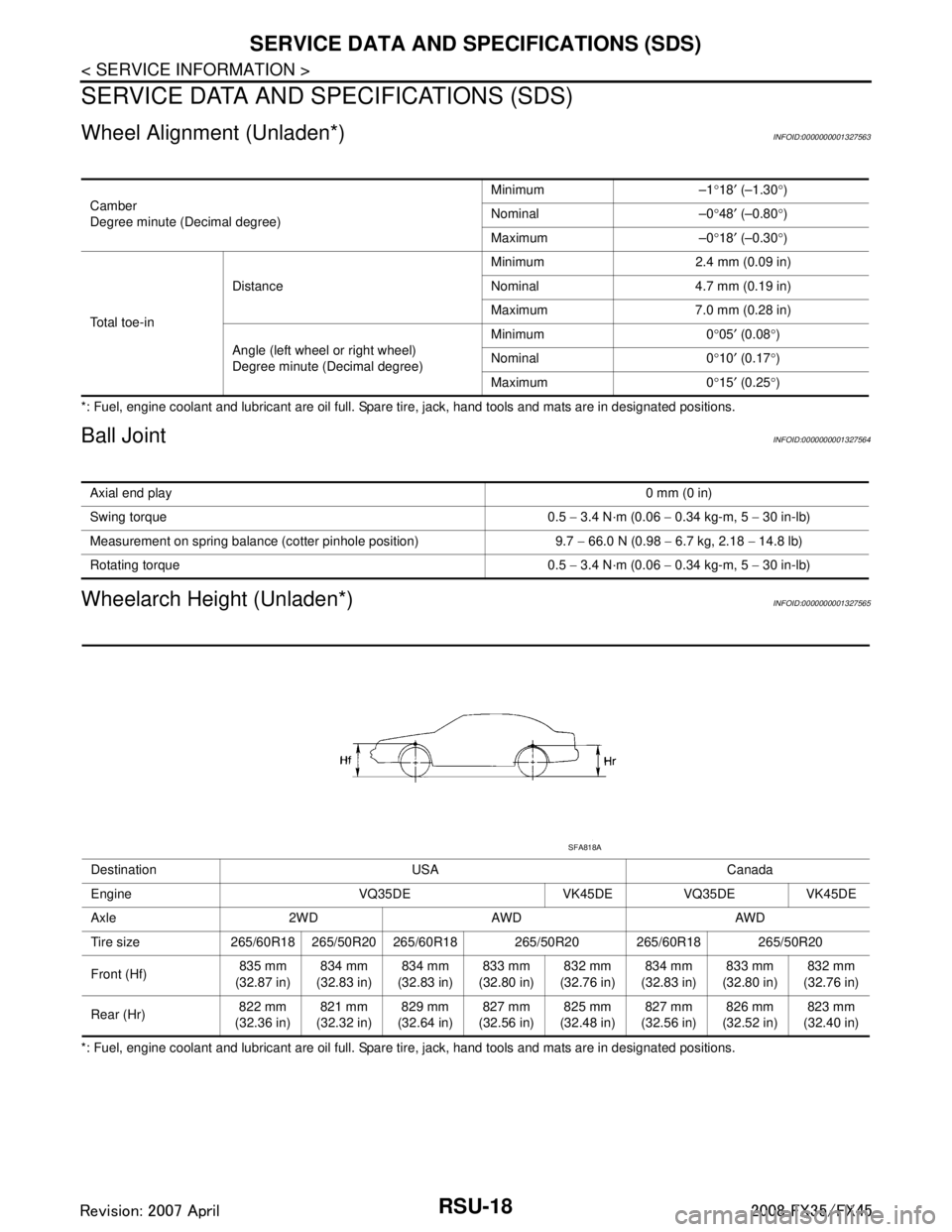
Wheel Alignment (Unladen*)INFOID:0000000001327563
*: Fuel, engine coolant and lubricant are oil full. Spare tire, jack, hand tools and mats are in designated positions.
Ball JointINFOID:0000000001327564
Wheelarch Height (Unladen*)INFOID:0000000001327565
*: Fuel, engine coolant and lubricant are oil full. Spare tire, jack, hand tools and mats are in designated positions.Camber
Degree minute (Decimal degree)
Minimum –1
°18 ′ (–1.30 °)
Nominal –0 °48 ′ (–0.80 °)
Maximum –0 °18 ′ (–0.30 °)
To t a l t o e - i n Distance
Minimum 2.4 mm (0.09 in)
Nominal 4.7 mm (0.19 in)
Maximum 7.0 mm (0.28 in)
Angle (left wheel or right wheel)
Degree minute (Decimal degree) Minimum 0
°05 ′ (0.08 °)
Nominal 0 °10 ′ (0.17 °)
Maximum 0 °15 ′ (0.25 °)
Axial end play 0 mm (0 in)
Swing torque 0.5 − 3.4 N·m (0.06 − 0.34 kg-m, 5 − 30 in-lb)
Measurement on spring balance (cotter pinhole position) 9.7 − 66.0 N (0.98 − 6.7 kg, 2.18 − 14.8 lb)
Rotating torque 0.5 − 3.4 N·m (0.06 − 0.34 kg-m, 5 − 30 in-lb)
Destination USA Canada
Engine VQ35DE VK45DE VQ35DE VK45DE
Axle 2WD AWD AWD
Tire size 265/60R18 265/50R20 265/60R18 265/50R20 265/60R18 265/50R20
Front (Hf) 835 mm
(32.87 in) 834 mm
(32.83 in) 834 mm
(32.83 in) 833 mm
(32.80 in) 832 mm
(32.76 in) 834 mm
(32.83 in) 833 mm
(32.80 in) 832 mm
(32.76 in)
Rear (Hr) 822 mm
(32.36 in) 821 mm
(32.32 in) 829 mm
(32.64 in) 827 mm
(32.56 in) 825 mm
(32.48 in) 827 mm
(32.56 in) 826 mm
(32.52 in) 823 mm
(32.40 in)
SFA818A
3AA93ABC3ACD3AC03ACA3AC03AC63AC53A913A773A893A873A873A8E3A773A983AC73AC93AC03AC3
3A893A873A873A8F3A773A9D3AAF3A8A3A8C3A863A9D3AAF3A8B3A8C