2008 INFINITI FX35 service reset
[x] Cancel search: service resetPage 1133 of 3924
COMBINATION METERSDI-7
< SERVICE INFORMATION >
C
DE
F
G H
I
J
L
M A
B
DI
N
O P
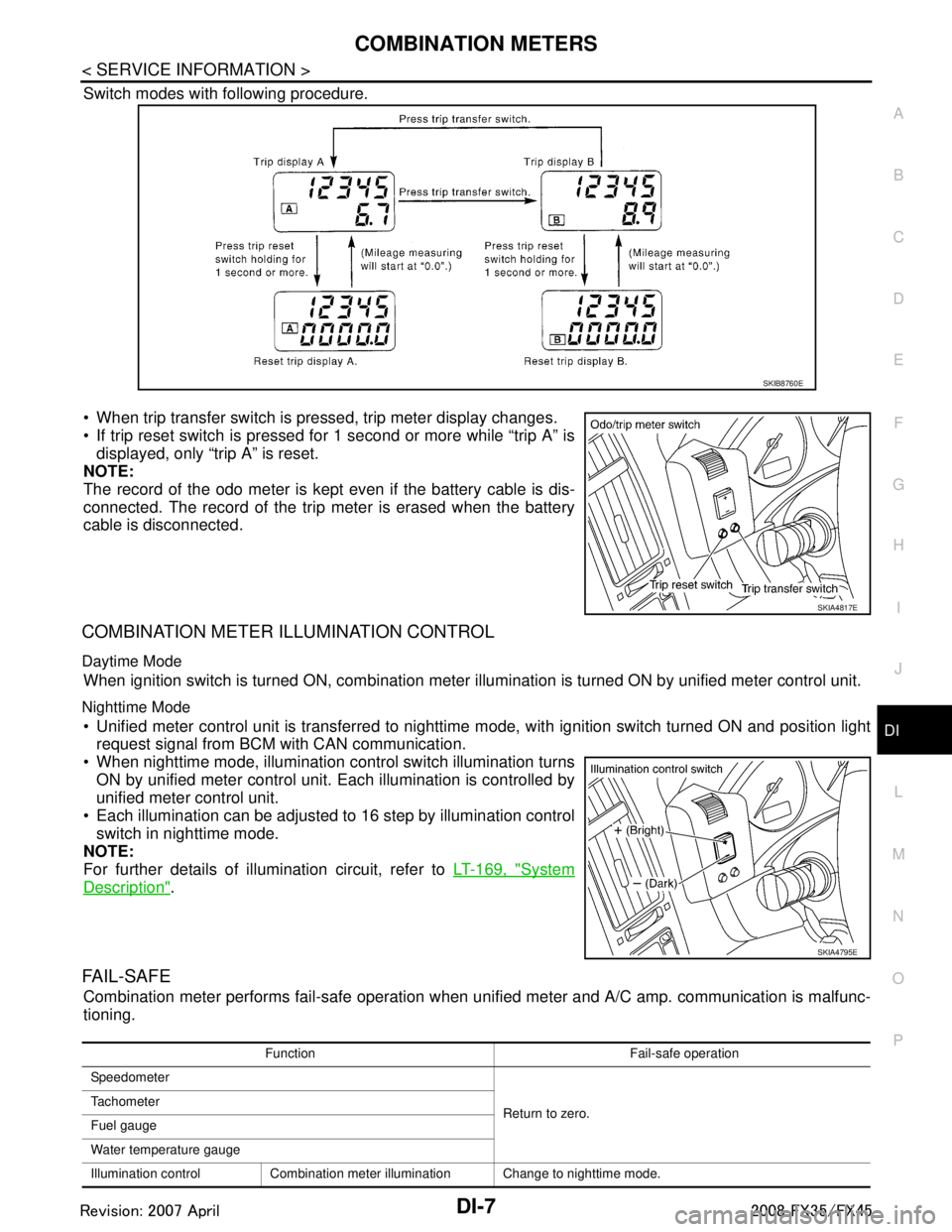
Switch modes with following procedure.
When trip transfer switch is pressed, trip meter display changes.
If trip reset switch is pressed for 1 second or more while “trip A” is displayed, only “trip A” is reset.
NOTE:
The record of the odo meter is kept even if the battery cable is dis-
connected. The record of the trip meter is erased when the battery
cable is disconnected.
COMBINATION METER ILLUMINATION CONTROL
Daytime Mode
When ignition switch is turned ON, combination meter il lumination is turned ON by unified meter control unit.
Nighttime Mode
Unified meter control unit is transferred to nighttime mode, with ignitio\
n switch turned ON and position light
request signal from BCM with CAN communication.
When nighttime mode, illumination c ontrol switch illumination turns
ON by unified meter control unit. Each illumination is controlled by
unified meter control unit.
Each illumination can be adjusted to 16 step by illumination control switch in nighttime mode.
NOTE:
For further details of illumination circuit, refer to LT-169, "
System
Description".
FA I L - S A F E
Combination meter performs fail-safe operation when unified meter and A/C amp. communication is malfunc-
tioning.
SKIB8760E
SKIA4817E
SKIA4795E
Function Fail-safe operation
Speedometer
Return to zero.
Tachometer
Fuel gauge
Water temperature gauge
Illumination control Combination meter illumination Change to nighttime mode.
3AA93ABC3ACD3AC03ACA3AC03AC63AC53A913A773A893A873A873A8E3A773A983AC73AC93AC03AC3
3A893A873A873A8F3A773A9D3AAF3A8A3A8C3A863A9D3AAF3A8B3A8C
Page 1139 of 3924
COMBINATION METERSDI-13
< SERVICE INFORMATION >
C
DE
F
G H
I
J
L
M A
B
DI
N
O P
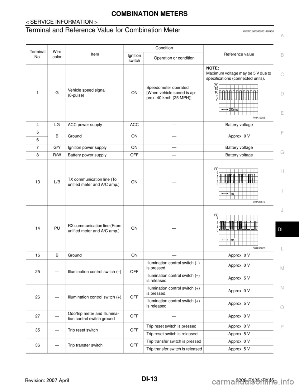
Terminal and Reference Va lue for Combination MeterINFOID:0000000001328438
Te r m i n a l
No. Wire
color Item Condition
Reference value
Ignition
switch Operation or condition
1G Vehicle speed signal
(8-pulse)
ONSpeedometer operated
[When vehicle speed is ap-
prox. 40 km/h (25 MPH)] NOTE:
Maximum voltage may be 5 V due to
specifications (connected units).
4 LG ACC power supply ACC — Battery voltage
5 B Ground ON — Approx. 0 V
6
7 G/Y Ignition power supply ON — Battery voltage
8 R/W Battery power supply OFF — Battery voltage
13 L/B TX communication line (To
unified meter and A/C amp.)
ON —
14 PU RX communication line (From
unified meter and A/C amp.) ON —
15 B Ground ON — Approx. 0 V
25 — Illumination control switch (–) OFF Illumination control switch (–)
is pressed.
Approx. 0 V
Illumination control switch (–)
is released. Approx. 5 V
26 — Illumination control switch (+) OFF Illumination control switch (+)
is pressed.
Approx. 0 V
Illumination control switch (+)
is released. Approx. 5 V
27 — Odo/trip meter and illumina-
tion control switch ground
OFF — Approx. 0 V
35 — Trip reset switch OFF Trip reset switch is pressed Approx. 0 V
Trip reset switch is released Approx. 5 V
36 — Trip transfer switch OFF Trip transfer switch is pressed Approx. 0 V
Trip transfer switch is released Approx. 5 V
PKIA1935E
SKIA3361E
SKIA3362E
3AA93ABC3ACD3AC03ACA3AC03AC63AC53A913A773A893A873A873A8E3A773A983AC73AC93AC03AC3
3A893A873A873A8F3A773A9D3AAF3A8A3A8C3A863A9D3AAF3A8B3A8C
Page 1140 of 3924
DI-14
< SERVICE INFORMATION >
COMBINATION METERS
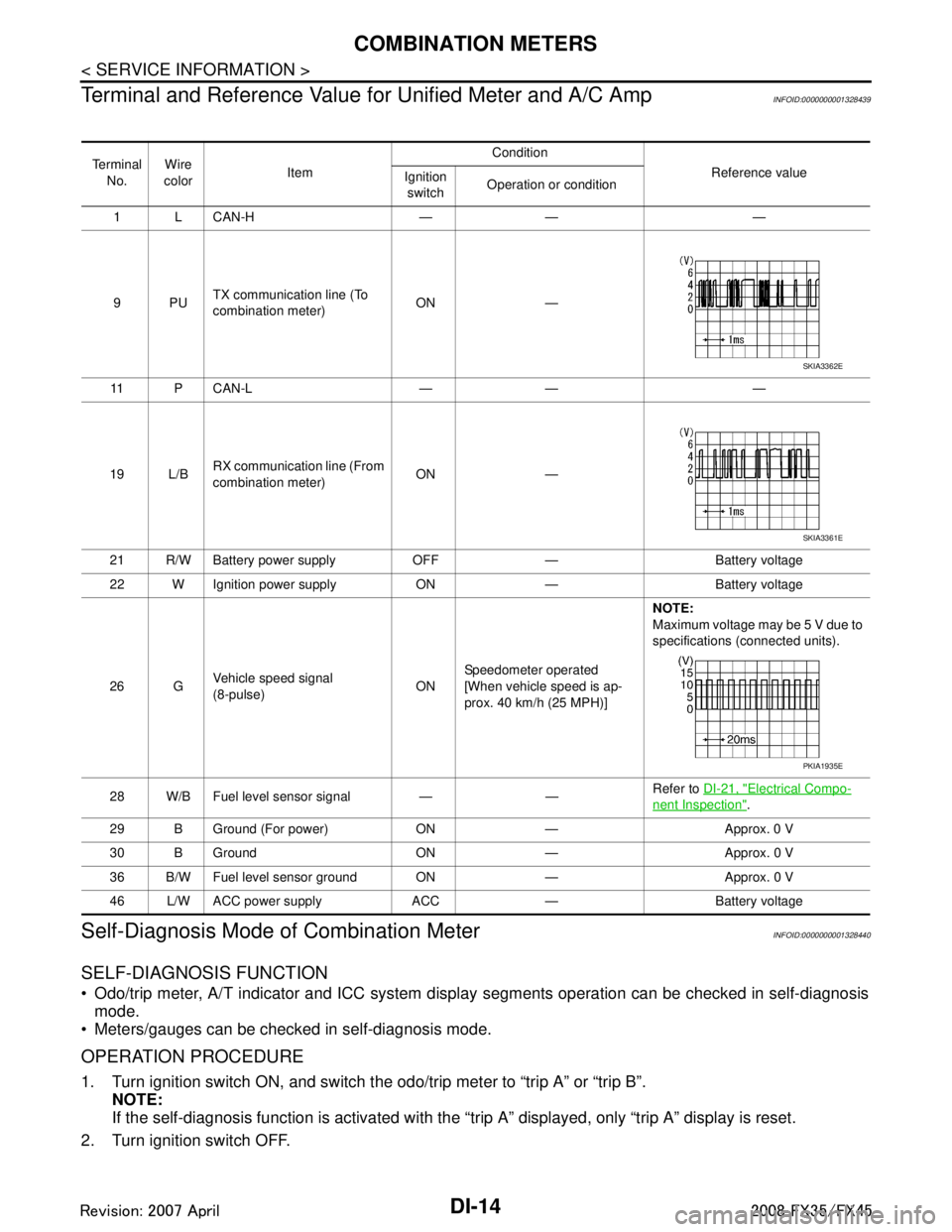
Terminal and Reference Value for Unified Meter and A/C Amp
INFOID:0000000001328439
Self-Diagnosis Mode of Combination MeterINFOID:0000000001328440
SELF-DIAGNOSIS FUNCTION
Odo/trip meter, A/T indicator and ICC system disp lay segments operation can be checked in self-diagnosis
mode.
Meters/gauges can be checked in self-diagnosis mode.
OPERATION PROCEDURE
1. Turn ignition switch ON, and switch the odo/trip meter to “trip A” or “trip B”. NOTE:
If the self-diagnosis function is activated with the “t rip A” displayed, only “trip A” display is reset.
2. Turn ignition switch OFF.
Te r m i n a l No. Wire
color Item Condition
Reference value
Ignition
switch Operation or condition
1 L CAN-H — — —
9PU TX communication line (To
combination meter) ON —
11 P C A N - L — — —
19 L/B RX communication line (From
combination meter) ON —
21 R/W Battery power supply OFF — Battery voltage
22 W Ignition power supply ON — Battery voltage
26 G Vehicle speed signal
(8-pulse)
ONSpeedometer operated
[When vehicle speed is ap-
prox. 40 km/h (25 MPH)] NOTE:
Maximum voltage may be 5 V due to
specifications (connected units).
28 W/B Fuel level sensor signal — — Refer to
DI-21, "
Electrical Compo-
nent Inspection".
29 B Ground (For power) ON — Approx. 0 V
30 B Ground ON — Approx. 0 V
36 B/W Fuel level sensor ground ON — Approx. 0 V
46 L/W ACC power supply ACC — Battery voltage
SKIA3362E
SKIA3361E
PKIA1935E
3AA93ABC3ACD3AC03ACA3AC03AC63AC53A913A773A893A873A873A8E3A773A983AC73AC93AC03AC3
3A893A873A873A8F3A773A9D3AAF3A8A3A8C3A863A9D3AAF3A8B3A8C
Page 1141 of 3924

COMBINATION METERSDI-15
< SERVICE INFORMATION >
C
DE
F
G H
I
J
L
M A
B
DI
N
O P
3. Turn ignition switch ON while pressing trip transfer switch and trip reset switch at the same time.
4. After ignition switch is turned ON, release trip transfer switch and trip reset switch (within 7 seconds after the ignition switch is
turned ON).
5. All the segments on the odo/trip meter, A/T indi cator and ICC system display illuminates, and simulta-
neously the low-fuel warning lamp indicator illuminates. At this time, the unified meter control unit is turned
to self-diagnosis mode.
NOTE:
Check odo/trip meter switch and combination meter power supply and ground circuit when self-diagno-
sis mode of combination meter does not start. Replace combination meter if the results of the check are
normal.
If any of the segments are not disp layed, replace combination meter.
6. Each meter/gauge activates during pressing trip reset switch. (Then low-fuel warning lamp turns OFF.)
NOTE:
If any of the meters/gauges are not activated, replace thecombination meter.
The figure is reference.
CONSULT-III Function (METER/M&A)INFOID:0000000001328441
Refer to DI-27, "CONSULT-III Function (METER/M&A)" in “UNIFIED METER AND A/C AMP”.
Trouble DiagnosisINFOID:0000000001328442
HOW TO PERFORM TROUBLE DIAGNOSIS
1. Confirm the symptom or customer complaint.
2. Perform preliminary check. Refer to "PRELIMINARY CHECK".
3. According to the symptom chart, repair or replace the cause of the symptom. Refer to DI-16, "
Symptom
Chart".
4. Does the meter operate normally? If so, GO TO 5. If not, GO TO 2.
5. INSPECTION END
PRELIMINARY CHECK
1.CHECK OPERATION OF SELF-DIAGNOSIS MODE (COMBINATION METER)
SKIA4817E
SKIA6170E
SKIA4831E
3AA93ABC3ACD3AC03ACA3AC03AC63AC53A913A773A893A873A873A8E3A773A983AC73AC93AC03AC3
3A893A873A873A8F3A773A9D3AAF3A8A3A8C3A863A9D3AAF3A8B3A8C
Page 1148 of 3924
DI-22
< SERVICE INFORMATION >
COMBINATION METERS
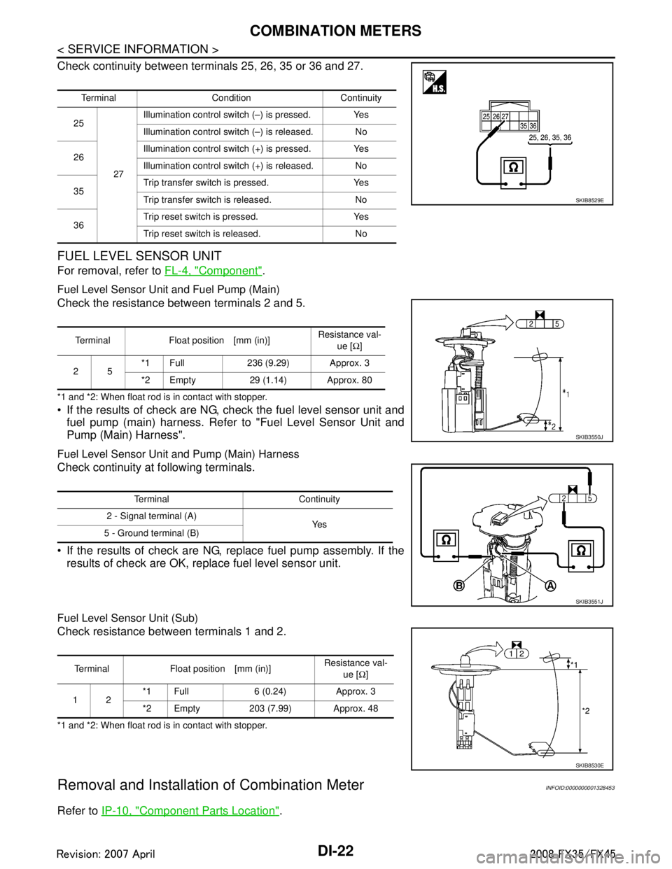
Check continuity between terminals 25, 26, 35 or 36 and 27.
FUEL LEVEL SENSOR UNIT
For removal, refer to FL-4, "Component".
Fuel Level Sensor Unit and Fuel Pump (Main)
Check the resistance between terminals 2 and 5.
*1 and *2: When float rod is in contact with stopper.
If the results of check are NG, check the fuel level sensor unit and
fuel pump (main) harness. Refer to "Fuel Level Sensor Unit and
Pump (Main) Harness".
Fuel Level Sensor Unit and Pump (Main) Harness
Check continuity at following terminals.
If the results of check are NG, replace fuel pump assembly. If the results of check are OK, replace fuel level sensor unit.
Fuel Level Sensor Unit (Sub)
Check resistance between terminals 1 and 2.
*1 and *2: When float rod is in contact with stopper.
Removal and Installation of Combination MeterINFOID:0000000001328453
Refer to IP-10, "Component Parts Location".
Terminal Condition Continuity
25
27Illumination control swit
ch (–) is pressed. Yes
Illumination control swit ch (–) is released. No
26 Illumination control swit
ch (+) is pressed. Yes
Illumination control swit ch (+) is released. No
35 Trip transfer switch is pressed. Yes
Trip transfer switch is released. No
36 Trip reset switch is pressed. Yes
Trip reset switch is released. No
SKIB8529E
Terminal Float position [mm (in)]
Resistance val-
ue [Ω]
25 *1 Full 236 (9.29) Approx. 3
*2 Empty 29 (1.14) Approx. 80
SKIB3550J
Terminal Continuity
2 - Signal terminal (A) Ye s
5 - Ground terminal (B)
SKIB3551J
Terminal Float position [mm (in)] Resistance val-
ue [Ω]
12 *1 Full 6 (0.24) Approx. 3
*2 Empty 203 (7.99) Approx. 48
SKIB8530E
3AA93ABC3ACD3AC03ACA3AC03AC63AC53A913A773A893A873A873A8E3A773A983AC73AC93AC03AC3
3A893A873A873A8F3A773A9D3AAF3A8A3A8C3A863A9D3AAF3A8B3A8C
Page 1220 of 3924
DI-94
< SERVICE INFORMATION >
COMPASS
COMPASS
Precaution for CompassINFOID:0000000001328520
NOTE:
Do not install the ski rack, antenna, etc. which is attach to the vehicle with a magnet base. It affects the oper-
ation of the compass.
When cleaning the mirror, use a paper towel or similar material dampened with glass cleaner. Do not spray glass cleaner directly on the mirror as it may c ause the liquid cleaner to enter the mirror housing.
System DescriptionINFOID:0000000001328521
This electronic compass is able to display 8 primary directions: N, NE, E, SE, S, SW, W, NW.
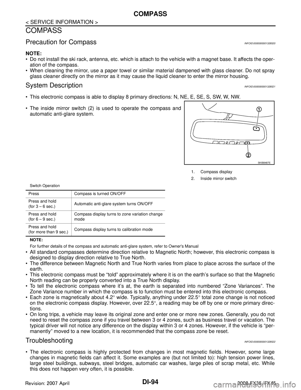
The inside mirror switch (2) is used to operate the compass and
automatic anti-glare system.
Switch Operation
NOTE:
For further details of the compass and automatic anti-glare system, refer to Owner's Manual
All standard compasses determine direction relative to Magnetic North; however, this electronic compass is
designed to display direction relative to True North.
The difference between Magnetic North and True North varies from place to place across the surface of the
earth.
This electronic compass must be “told” approximately w here it is on the earth’s surface so that the Magnetic
North reading can be properly converted into a True North display.
To tell the electronic compass where it’s at, the earth is separated into numbered “Zone Variances”. The
Zone Variance number in which the compass is to function must be entered into this electronic compass.
Each zone is magnetically about 4.2 ° wide. Typically, anything under 22.5 ° total zone change is not noticed
on the electronic compass display. However, over 22.5 °, a reading may be off by one or more primary direc-
tions.
On long trips, a vehicle may leave its original zone and enter one or more new zones. Generally, you do not need to reset the compass zone if you travel between 3 or 4 zones, such as business travel or vacation. The
typical driver will not notice any difference on the display within 3 or 4 zones. However, if the vehicle is “per-
manently” moved to a new location, it is recommended that the compass zone be reset.
TroubleshootingINFOID:0000000001328522
The electronic compass is highly protected from changes in most magnetic fields. However, some large changes in magnetic fields can affect it. Some examples are (but not limited to): high tension power lines,
large steel buildings, subways, steel bridges, automatic car washes, large piles of scrap metal, etc. While
this does not happen very often, it is possible.
1. Compass display
2. Inside mirror switch
SKIB8487E
Press Compass is turned ON/OFF
Press and hold
(for 3 – 6 sec.) Automatic anti-glare system turns ON/OFF
Press and hold
(for 6 – 9 sec.) Compass display turns to zone variation change
mode
Press and hold
(for more than 9 sec.) Compass display turns to calibration mode
3AA93ABC3ACD3AC03ACA3AC03AC63AC53A913A773A893A873A873A8E3A773A983AC73AC93AC03AC3
3A893A873A873A8F3A773A9D3AAF3A8A3A8C3A863A9D3AAF3A8B3A8C
Page 1221 of 3924
COMPASSDI-95
< SERVICE INFORMATION >
C
DE
F
G H
I
J
L
M A
B
DI
N
O P
During normal operation, the Compass Mirror will cont inuously update the compass calibration to adjust for
gradual changes in the vehicle's magnetic “remnant” field. If the vehicle is subjected to high magnetic influ-
ences, the compass may appear to indicate false headings , become locked, or appear that it is unable to be
calibrated. If this occurs, perform the calibration procedure.
If at any time the compass continually displays the inco rrect direction or the reading is erratic or locked, ver-
ify the correct zone variance.
Troubleshooting Chart
Zone Variation Setting ProcedureINFOID:0000000001328523
NOTE:
The zone setting is factory preset (“default” setting) to zone 8.
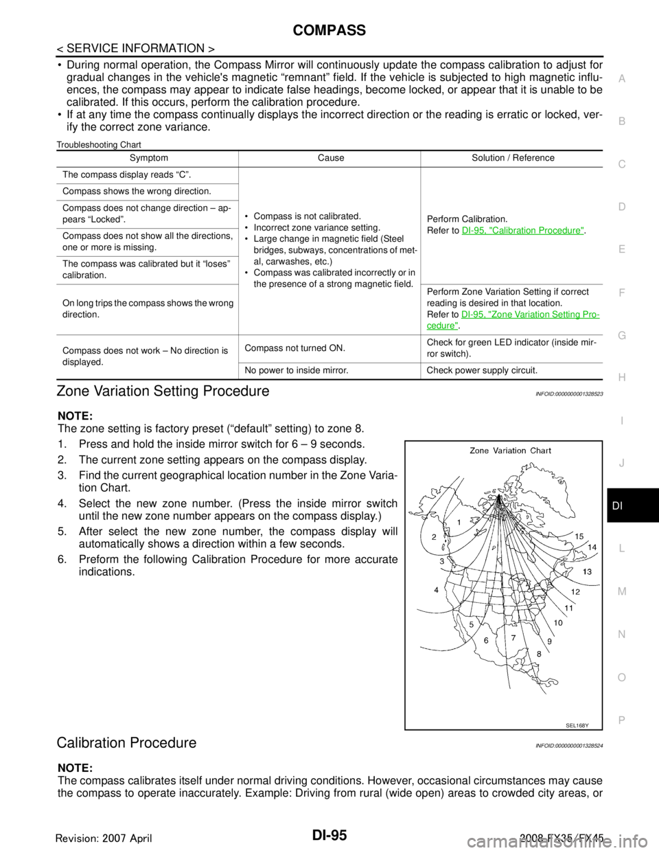
1. Press and hold the inside mirror switch for 6 – 9 seconds.
2. The current zone setting appears on the compass display.
3. Find the current geographical location number in the Zone Varia-
tion Chart.
4. Select the new zone number. (Press the inside mirror switch until the new zone number appears on the compass display.)
5. After select the new zone number, the compass display will automatically shows a direction within a few seconds.
6. Preform the following Calibration Procedure for more accurate indications.
Calibration ProcedureINFOID:0000000001328524
NOTE:
The compass calibrates itself under normal driving conditions. However, occasional circumstances may cause
the compass to operate inaccurately. Example: Driving from rural (wide open) areas to crowded city areas, or
Symptom Cause Solution / Reference
The compass display reads “C”.
Compass is not calibrated.
Incorrect zone variance setting.
Large change in magnetic field (Steel bridges, subways, concentrations of met-
al, carwashes, etc.)
Compass was calibrated incorrectly or in
the presence of a strong magnetic field. Perform Calibration.
Refer to
DI-95, "
Calibration Procedure".
Compass shows the wrong direction.
Compass does not change direction – ap-
pears “Locked”.
Compass does not show all the directions,
one or more is missing.
The compass was calibrated but it “loses”
calibration.
On long trips the compass shows the wrong
direction.
Perform Zone Variatio
n Setting if correct
reading is desired in that location.
Refer to DI-95, "
Zone Variation Setting Pro-
cedure".
Compass does not work – No direction is
displayed. Compass not turned ON.
Check for green LED indicator (inside mir-
ror switch).
No power to inside mirror. Check power supply circuit.
SEL168Y
3AA93ABC3ACD3AC03ACA3AC03AC63AC53A913A773A893A873A873A8E3A773A983AC73AC93AC03AC3
3A893A873A873A8F3A773A9D3AAF3A8A3A8C3A863A9D3AAF3A8B3A8C
Page 1272 of 3924
![INFINITI FX35 2008 Service Manual
EC-32
< SERVICE INFORMATION >[VQ35DE]
ENGINE CONTROL SYSTEM
*1: This sensor is not used to control the engine system under normal conditions.
*2: This signal is sent to the ECM through CAN communicat INFINITI FX35 2008 Service Manual
EC-32
< SERVICE INFORMATION >[VQ35DE]
ENGINE CONTROL SYSTEM
*1: This sensor is not used to control the engine system under normal conditions.
*2: This signal is sent to the ECM through CAN communicat](/manual-img/42/57017/w960_57017-1271.png)
EC-32
< SERVICE INFORMATION >[VQ35DE]
ENGINE CONTROL SYSTEM
*1: This sensor is not used to control the engine system under normal conditions.
*2: This signal is sent to the ECM through CAN communication line.
*3: ECM determines the start signal status by the signals of engine speed and battery voltage.
SYSTEM DESCRIPTION
The amount of fuel injected from the fuel injector is
determined by the ECM. The ECM controls the length of
time the valve remains open (injection pulse duration). T he amount of fuel injected is a program value in the
ECM memory. The program value is preset by engi ne operating conditions. These conditions are determined
by input signals (for engine speed and intake air) from both the crankshaft position sensor and the mass air
flow sensor.
VARIOUS FUEL INJECTION I NCREASE/DECREASE COMPENSATION
In addition, the amount of fuel injected is compens ated to improve engine performance under various operat-
ing conditions as listed below.
When starting the engine
During acceleration
Hot-engine operation
When selector lever is changed from N to D
High-load, high-speed operation
During high engine speed operation
MIXTURE RATIO FEEDBACK CONTROL (CLOSED LOOP CONTROL)
The mixture ratio feedback system prov ides the best air-fuel mixture ratio for driveability and emission control.
The three way catalyst 1 can then better reduce CO, HC and NOx emissions. This system uses air fuel ratio
Sensor Input Signal to ECM ECM function Actuator
Crankshaft position sensor (POS) Engine speed*
3
Piston position
Fuel injection
& mixture ratio
controlFuel injector
Camshaft position sensor (PHASE)
Mass air flow sensor Amount of intake air
Engine coolant temperature sensor Engine coolant temperature
Air fuel ratio (A/F) sensor 1 Density of oxygen in exhaust gas
Throttle position sensor Throttle position
Accelerator pedal position sensor Accelerator pedal position
Park/neutral position (PNP) switch Gear position
Knock sensor Engine knocking condition
Battery
Battery voltage*
3
Power steering pressure sensor Power steering operation
Heated oxygen sensor 2*
1Density of oxygen in exhaust gas
Air conditioner switch Air conditioner operation*
2
Wheel sensorVehicle speed*2
PBIB3020E
3AA93ABC3ACD3AC03ACA3AC03AC63AC53A913A773A893A873A873A8E3A773A983AC73AC93AC03AC3
3A893A873A873A8F3A773A9D3AAF3A8A3A8C3A863A9D3AAF3A8B3A8C