2008 INFINITI FX35 service
[x] Cancel search: servicePage 1237 of 3924
REAR VIEW MONITORDI-111
< SERVICE INFORMATION >
C
DE
F
G H
I
J
L
M A
B
DI
N
O P
NG >> Repair or replace power supply and ground circuit.
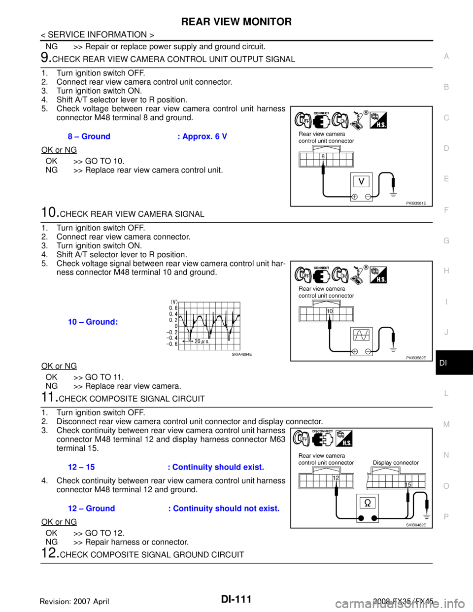
9.CHECK REAR VIEW CAMERA CONTROL UNIT OUTPUT SIGNAL
1. Turn ignition switch OFF.
2. Connect rear view camera control unit connector.
3. Turn ignition switch ON.
4. Shift A/T selector lever to R position.
5. Check voltage between rear view camera control unit harness connector M48 terminal 8 and ground.
OK or NG
OK >> GO TO 10.
NG >> Replace rear view camera control unit.
10.CHECK REAR VIEW CAMERA SIGNAL
1. Turn ignition switch OFF.
2. Connect rear view camera connector.
3. Turn ignition switch ON.
4. Shift A/T selector lever to R position.
5. Check voltage signal between rear view camera control unit har- ness connector M48 terminal 10 and ground.
OK or NG
OK >> GO TO 11.
NG >> Replace rear view camera.
11 .CHECK COMPOSITE SIGNAL CIRCUIT
1. Turn ignition switch OFF.
2. Disconnect rear view camera control unit connector and display connector.
3. Check continuity between rear view camera control unit harness connector M48 terminal 12 and display harness connector M63
terminal 15.
4. Check continuity between rear view camera control unit harness connector M48 terminal 12 and ground.
OK or NG
OK >> GO TO 12.
NG >> Repair harness or connector.
12.CHECK COMPOSITE SI GNAL GROUND CIRCUIT
8 – Ground : Approx. 6 V
PKIB3581E
10 – Ground:
PKIB3582ESKIA4894E
12 – 15 : Continuity should exist.
12 – Ground : Continuity should not exist.
SKIB0482E
3AA93ABC3ACD3AC03ACA3AC03AC63AC53A913A773A893A873A873A8E3A773A983AC73AC93AC03AC3
3A893A873A873A8F3A773A9D3AAF3A8A3A8C3A863A9D3AAF3A8B3A8C
Page 1238 of 3924
DI-112
< SERVICE INFORMATION >
REAR VIEW MONITOR
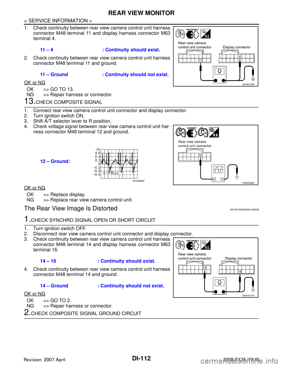
1. Check continuity between rear view camera control unit harnessconnector M48 terminal 11 and display harness connector M63
terminal 4.
2. Check continuity between rear view camera control unit harness connector M48 terminal 11 and ground.
OK or NG
OK >> GO TO 13.
NG >> Repair harness or connector.
13.CHECK COMPOSITE SIGNAL
1. Connect rear view camera control unit connector and display connector.
2. Turn ignition switch ON.
3. Shift A/T selector lever to R position.
4. Check voltage signal between rear view camera control unit har- ness connector M48 terminal 12 and ground.
OK or NG
OK >> Replace display.
NG >> Replace rear view camera control unit.
The Rear View Image Is DistortedINFOID:0000000001328538
1.CHECK SYNCHRO SIGNAL OPEN OR SHORT CIRCUIT
1. Turn ignition switch OFF.
2. Disconnect rear view camera control unit connector and display connector.
3. Check continuity between rear view camera control unit harness connector M48 terminal 14 and display harness connector M63
terminal 16.
4. Check continuity between rear view camera control unit harness connector M48 terminal 14 and ground.
OK or NG
OK >> GO TO 2.
NG >> Repair harness or connector.
2.CHECK COMPOSITE SI GNAL GROUND CIRCUIT
11 – 4 : Continuity should exist.
11 – Ground : Continuity should not exist.
SKIA5102E
12 – Ground:
PKIB3583ESKIA4896E
14 – 16 : Continuity should exist.
14 – Ground : Continuity should not exist.
SKIA5101E
3AA93ABC3ACD3AC03ACA3AC03AC63AC53A913A773A893A873A873A8E3A773A983AC73AC93AC03AC3
3A893A873A873A8F3A773A9D3AAF3A8A3A8C3A863A9D3AAF3A8B3A8C
Page 1239 of 3924
REAR VIEW MONITORDI-113
< SERVICE INFORMATION >
C
DE
F
G H
I
J
L
M A
B
DI
N
O P
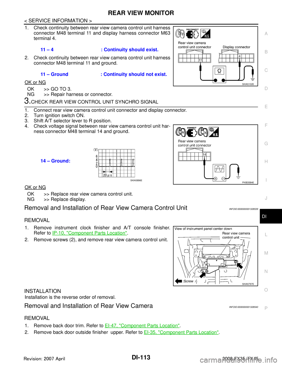
1. Check continuity between rear view camera control unit harness connector M48 terminal 11 and display harness connector M63
terminal 4.
2. Check continuity between rear view camera control unit harness connector M48 terminal 11 and ground.
OK or NG
OK >> GO TO 3.
NG >> Repair harness or connector.
3.CHECK REAR VIEW CONTROL UNIT SYNCHRO SIGNAL
1. Connect rear view camera control unit connector and display connector.
2. Turn ignition switch ON.
3. Shift A/T selector lever to R position.
4. Check voltage signal between rear view camera control unit har- ness connector M48 terminal 14 and ground.
OK or NG
OK >> Replace rear view camera control unit.
NG >> Replace display.
Removal and Installation of R ear View Camera Control UnitINFOID:0000000001328539
REMOVAL
1. Remove instrument clock finisher and A/T console finisher.
Refer to IP-10, "
Component Parts Location".
2. Remove screws (2), and remove rear view camera control unit.
INSTALLATION
Installation is the reverse order of removal.
Removal and Installation of Rear View CameraINFOID:0000000001328540
REMOVAL
1. Remove back door trim. Refer to EI-47, "Component Parts Location".
2. Remove back door outside finisher upper. Refer to EI-35, "
Component Parts Location".
11 – 4 : Continuity should exist.
11 – Ground : Continuity should not exist.
SKIA5102E
14 – Ground:
PKIB3584ESKIA5896E
SKIA5797E
3AA93ABC3ACD3AC03ACA3AC03AC63AC53A913A773A893A873A873A8E3A773A983AC73AC93AC03AC3
3A893A873A873A8F3A773A9D3AAF3A8A3A8C3A863A9D3AAF3A8B3A8C
Page 1240 of 3924
DI-114
< SERVICE INFORMATION >
REAR VIEW MONITOR
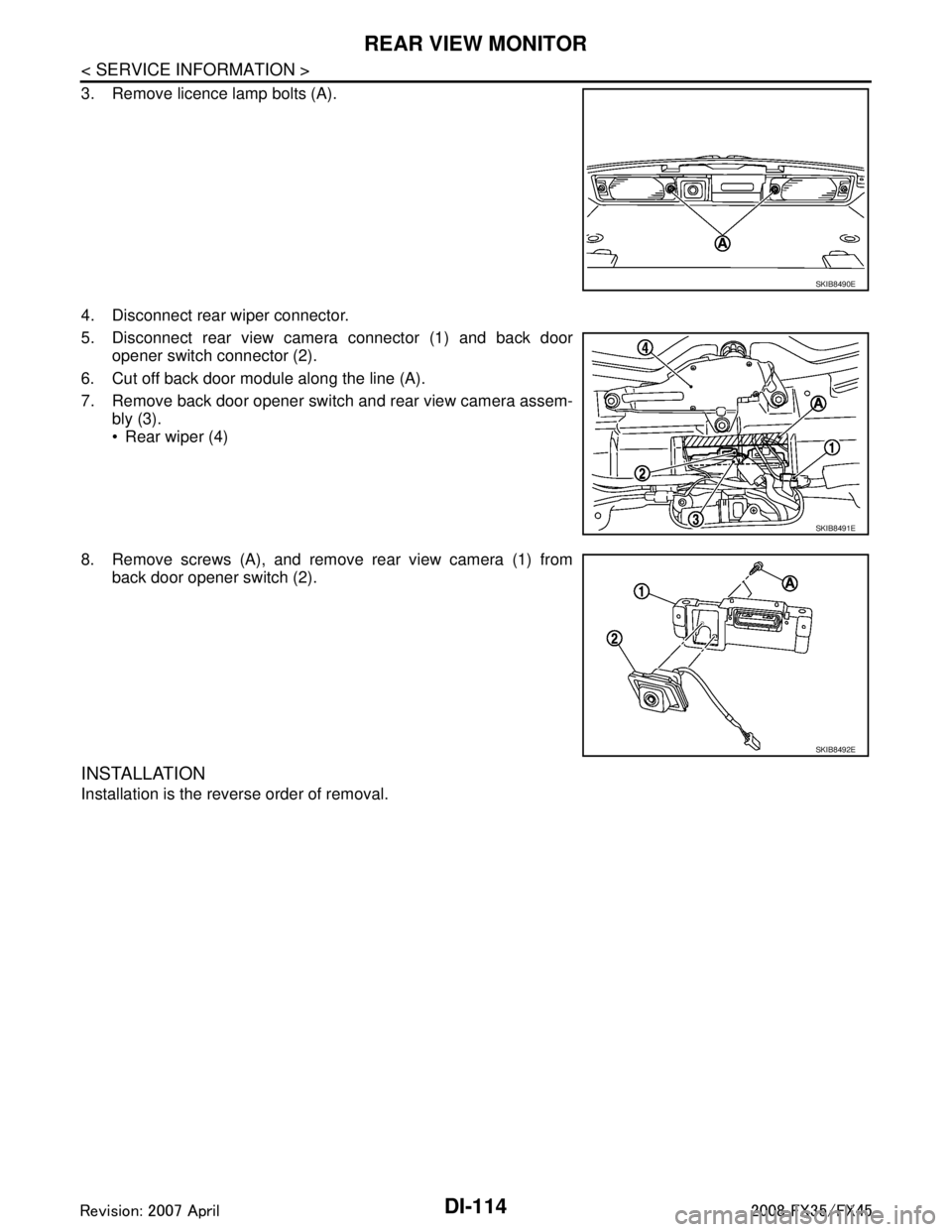
3. Remove licence lamp bolts (A).
4. Disconnect rear wiper connector.
5. Disconnect rear view camera connector (1) and back dooropener switch connector (2).
6. Cut off back door module along the line (A).
7. Remove back door opener switch and rear view camera assem- bly (3).
Rear wiper (4)
8. Remove screws (A), and remove rear view camera (1) from back door opener switch (2).
INSTALLATION
Installation is the reverse order of removal.
SKIB8490E
SKIB8491E
SKIB8492E
3AA93ABC3ACD3AC03ACA3AC03AC63AC53A913A773A893A873A873A8E3A773A983AC73AC93AC03AC3
3A893A873A873A8F3A773A9D3AAF3A8A3A8C3A863A9D3AAF3A8B3A8C
Page 1241 of 3924
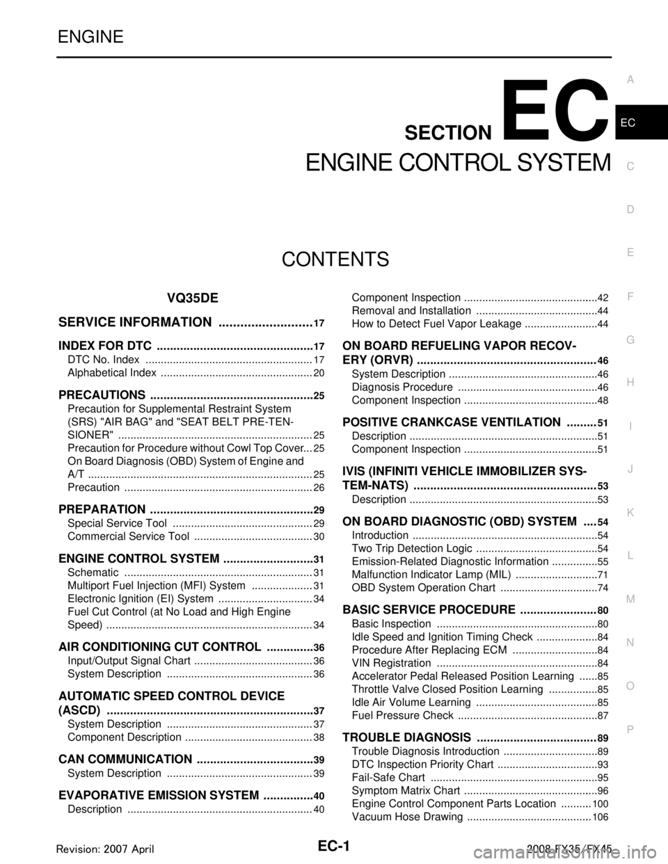
EC-1
ENGINE
C
DE
F
G H
I
J
K L
M
SECTION EC
A
EC
N
O P
CONTENTS
ENGINE CONTROL SYSTEM
VQ35DE
SERVICE INFORMATION .. .........................
17
INDEX FOR DTC ............................................ ....17
DTC No. Index .................................................... ....17
Alphabetical Index ...................................................20
PRECAUTIONS ..................................................25
Precaution for Supplemental Restraint System
(SRS) "AIR BAG" and "SEAT BELT PRE-TEN-
SIONER" ............................................................. ....
25
Precaution for Procedure without Cowl Top Cover ....25
On Board Diagnosis (OBD) System of Engine and
A/T ...........................................................................
25
Precaution ...............................................................26
PREPARATION ..................................................29
Special Service Tool ........................................... ....29
Commercial Service Tool ........................................30
ENGINE CONTROL SYSTEM ............................31
Schematic ........................................................... ....31
Multiport Fuel Injection (MFI) System .....................31
Electronic Ignition (EI) System ................................34
Fuel Cut Control (at No Load and High Engine
Speed) .....................................................................
34
AIR CONDITIONING CUT CONTROL ...............36
Input/Output Signal Chart .................................... ....36
System Description .................................................36
AUTOMATIC SPEED CONTROL DEVICE
(ASCD) ...............................................................
37
System Description ............................................. ....37
Component Description ...........................................38
CAN COMMUNICATION ....................................39
System Description ............................................. ....39
EVAPORATIVE EMISSION SYSTEM ................40
Description .......................................................... ....40
Component Inspection ......................................... ....42
Removal and Installation .........................................44
How to Detect Fuel Vapor Leakage .........................44
ON BOARD REFUELING VAPOR RECOV-
ERY (ORVR) ......................................................
46
System Description ..................................................46
Diagnosis Procedure ...............................................46
Component Inspection .............................................48
POSITIVE CRANKCASE VENTILATION .........51
Description ...............................................................51
Component Inspection .............................................51
IVIS (INFINITI VEHICLE IMMOBILIZER SYS-
TEM-NATS) .......................................................
53
Description ...............................................................53
ON BOARD DIAGNOSTIC (OBD) SYSTEM ....54
Introduction ..............................................................54
Two Trip Detection Logic .........................................54
Emission-Related Diagnostic Information ................55
Malfunction Indicator Lamp (MIL) ............................71
OBD System Operation Chart .................................74
BASIC SERVICE PROCEDURE .......................80
Basic Inspection ......................................................80
Idle Speed and Ignition Timing Check .....................84
Procedure After Replacing ECM .............................84
VIN Registration ......................................................84
Accelerator Pedal Released Position Learning .......85
Throttle Valve Closed Position Learning .................85
Idle Air Volume Learning .........................................85
Fuel Pressure Check ...............................................87
TROUBLE DIAGNOSIS ....................................89
Trouble Diagnosis Introduction ................................89
DTC Inspection Priority Chart ..................................93
Fail-Safe Chart ........................................................95
Symptom Matrix Chart .............................................96
Engine Control Component Parts Location ...........100
Vacuum Hose Drawing ..........................................106
3AA93ABC3ACD3AC03ACA3AC03AC63AC53A913A773A893A873A873A8E3A773A983AC73AC93AC03AC3
3A893A873A873A8F3A773A9D3AAF3A8A3A8C3A863A9D3AAF3A8B3A8C
Page 1248 of 3924

EC-8
Component Inspection ...........................................545
ASCD INDICATOR ..........................................547
Component Description ....................................... ..547
CONSULT-III Reference Value in Data Monitor
Mode .................................................................... ..
547
Wiring Diagram ......................................................548
Diagnosis Procedure .............................................548
ELECTRICAL LOAD SIGNAL .........................550
Description ........................................................... ..550
CONSULT-III Reference Value in Data Monitor
Mode .................................................................... ..
550
Diagnosis Procedure .............................................550
FUEL INJECTOR .............................................552
Component Description ....................................... ..552
CONSULT-III Reference Value in Data Monitor
Mode .................................................................... ..
552
Wiring Diagram ......................................................553
Diagnosis Procedure .............................................554
Component Inspection ...........................................557
Removal and Installation .......................................557
FUEL PUMP .....................................................558
Description ........................................................... ..558
CONSULT-III Reference Value in Data Monitor
Mode .................................................................... ..
558
Wiring Diagram ......................................................559
Diagnosis Procedure .............................................560
Component Inspection ...........................................562
Removal and Installation .......................................562
ICC BRAKE SWITCH ......................................563
Component Description ....................................... ..563
CONSULT-III Reference Value in Data Monitor
Mode .................................................................... ..
563
Wiring Diagram ......................................................564
Diagnosis Procedure .............................................565
Component Inspection ...........................................567
IGNITION SIGNAL ...........................................569
Component Description ....................................... ..569
Wiring Diagram ......................................................570
Diagnosis Procedure .............................................575
Component Inspection ...........................................578
Removal and Installation .......................................580
REFRIGERANT PRESSURE SENSOR ..........581
Component Description ....................................... ..581
Wiring Diagram ......................................................582
Diagnosis Procedure .............................................583
Removal and Installation .......................................585
SNOW MODE SWITCH ...................................586
Description ........................................................... ..586
CONSULT-III Reference Value in Data Monitor
Mode .................................................................... ..
586
Wiring Diagram ......................................................587
Diagnosis Procedure .............................................587
Component Inspection ...........................................589
MIL AND DATA LINK CONNECTOR ...............591
Wiring Diagram .................................................... .591
SERVICE DATA AND SPECIFICATIONS
(SDS) ................................................................
593
Fuel Pressure ....................................................... .593
Idle Speed and Ignition Timing .............................593
Calculated Load Value ..........................................593
Mass Air Flow Sensor ...........................................593
Intake Air Temperature Sensor .............................593
Engine Coolant Temperature Sensor ...................593
Air Fuel Ratio (A/F) Sensor 1 Heater ....................593
Heated Oxygen sensor 2 Heater ..........................593
Crankshaft Position Sensor (POS) .......................594
Camshaft Position Sensor (PHASE) .....................594
Throttle Control Motor .......................................... .594
Fuel Injector ..........................................................594
Fuel Pump .............................................................594
VK45DE
SERVICE INFORMATION .. .......................
595
INDEX FOR DTC ............................................ ..595
DTC No. Index ..................................................... .595
Alphabetical Index .................................................598
PRECAUTIONS .............................................. ..603
Precaution for Supplemental Restraint System
(SRS) "AIR BAG" and "SEAT BELT PRE-TEN-
SIONER" .............................................................. .
603
Precaution for Procedure without Cowl Top Cover .603
On Board Diagnosis (OBD) System of Engine and
A/T ........................................................................
603
Precaution .............................................................604
PREPARATION ................................................607
Special Service Tool ............................................ .607
Commercial Service Tool ......................................608
ENGINE CONTROL SYSTEM ..........................609
Schematic ............................................................ .609
Multiport Fuel Injection (MFI) System ...................609
Electronic Ignition (EI) System ..............................612
Fuel Cut Control (at No Load and High Engine
Speed) ..................................................................
612
AIR CONDITIONING CUT CONTROL .............614
Input/Output Signal Chart .................................... .614
System Description ...............................................614
AUTOMATIC SPEED CONTROL DEVICE
(ASCD) ..............................................................
615
System Description .............................................. .615
Component Description ........................................616
CAN COMMUNICATION ..................................617
System Description .............................................. .617
EVAPORATIVE EMISSION SYSTEM ..............618
Description ........................................................... .618
Component Inspection ..........................................620
3AA93ABC3ACD3AC03ACA3AC03AC63AC53A913A773A893A873A873A8E3A773A983AC73AC93AC03AC3
3A893A873A873A8F3A773A9D3AAF3A8A3A8C3A863A9D3AAF3A8B3A8C
Page 1249 of 3924

EC-9
C
DE
F
G H
I
J
K L
M
EC A
N
O P
Removal and Installation .....................................
..
622
How to Detect Fuel Vapor Leakage ......................622
ON BOARD REFUELING VAPOR RECOV-
ERY (ORVR) .....................................................
624
System Description ............................................. ..624
Diagnosis Procedure .............................................624
Component Inspection ..........................................626
POSITIVE CRANKCASE VENTILATION ........629
Description .......................................................... ..629
Component Inspection ..........................................629
IVIS (INFINITI VEHICLE IMMOBILIZER SYS-
TEM-NATS) ......................................................
631
Description .......................................................... ..631
ON BOARD DIAGNOSTIC (OBD) SYSTEM ....632
Introduction ......................................................... ..632
Two Trip Detection Logic ......................................632
Emission-related Diagnostic Information ...............633
Malfunction Indicator Lamp (MIL) ..........................649
OBD System Operation Chart ...............................652
BASIC SERVICE PROCEDURE ......................658
Basic Inspection .................................................. ..658
Idle Speed and Ignition Timing Check ..................661
Procedure After Replacing ECM ...........................662
VIN Registration ....................................................662
Accelerator Pedal Released Position Learning .....662
Throttle Valve Closed Position Learning ...............663
Idle Air Volume Learning .......................................663
Fuel Pressure Check .............................................665
TROUBLE DIAGNOSIS ...................................666
Trouble Diagnosis Introduction ........................... ..666
DTC Inspection Priority Chart ...............................670
Fail-Safe Chart ......................................................671
Symptom Matrix Chart ..........................................673
Engine Control Component Parts Location ...........677
Vacuum Hose Drawing .........................................684
Circuit Diagram .....................................................685
ECM Harness Connector Terminal Layout ...........687
ECM Terminal and Reference Value ....................687
CONSULT-III Function (ENGINE) .........................695
Generic Scan Tool (GST) Function .......................704
CONSULT-III Reference Value in Data Monitor
Mode ................................................................... ..
705
TROUBLE DIAGNOSIS - SPECIFICATION
VALUE ..............................................................
709
Description .......................................................... ..709
Testing Condition ..................................................709
Inspection Procedure ............................................709
Diagnosis Procedure .............................................710
TROUBLE DIAGNOSIS FOR INTERMITTENT
INCIDENT .........................................................
717
Description .......................................................... ..717
Diagnosis Procedure .............................................717
POWER SUPPLY AND GROUND CIRCUIT ..718
Wiring Diagram .................................................... ..718
Diagnosis Procedure .............................................719
Ground Inspection .................................................723
DTC U1000, U1001 CAN COMMUNICATION
LINE .................................................................
724
Description .............................................................724
On Board Diagnosis Logic .....................................724
DTC Confirmation Procedure ................................724
Wiring Diagram ......................................................725
Diagnosis Procedure .............................................725
DTC U1010 CAN COMMUNICATION .............726
Description .............................................................726
On Board Diagnosis Logic .....................................726
DTC Confirmation Procedure ................................726
Diagnosis Procedure .............................................726
DTC P0011, P0021 IVT CONTROL ................727
Description .............................................................727
CONSULT-III Reference Value in Data Monitor
Mode ......................................................................
728
On Board Diagnosis Logic .....................................728
DTC Confirmation Procedure ................................728
Wiring Diagram ......................................................730
Diagnosis Procedure .............................................733
Component Inspection ...........................................737
Removal and Installation .......................................738
DTC P0031, P0032, P0051, P0052 A/F SEN-
SOR 1 HEATER ..............................................
739
Description .............................................................739
CONSULT-III Reference Value in Data Monitor
Mode ......................................................................
739
On Board Diagnosis Logic .....................................739
DTC Confirmation Procedure ................................739
Wiring Diagram ......................................................740
Diagnosis Procedure .............................................743
Component Inspection ...........................................744
Removal and Installation .......................................745
DTC P0037, P0038, P0057, P0058 HO2S2
HEATER ..........................................................
746
Description .............................................................746
CONSULT-III Reference Value in Data Monitor
Mode ......................................................................
746
On Board Diagnosis Logic .....................................746
DTC Confirmation Procedure ................................746
Wiring Diagram ......................................................748
Diagnosis Procedure .............................................751
Component Inspection ...........................................752
Removal and Installation .......................................753
DTC P0075, P0081 IVT CONTROL SOLE-
NOID VALVE ...................................................
754
Component Description .........................................754
CONSULT-III Reference Value in Data Monitor
Mode ......................................................................
754
On Board Diagnosis Logic .....................................754
3AA93ABC3ACD3AC03ACA3AC03AC63AC53A913A773A893A873A873A8E3A773A983AC73AC93AC03AC3
3A893A873A873A8F3A773A9D3AAF3A8A3A8C3A863A9D3AAF3A8B3A8C
Page 1256 of 3924

EC-16
Description ...........................................................1182
CONSULT-III Reference Value in Data Monitor
Mode ....................................................................
1182
Wiring Diagram ....................................................1183
Diagnosis Procedure ...........................................1183
Component Inspection .........................................1185
VARIABLE INDUCTION AIR CONTROL SYS-
TEM (VIAS) .....................................................
1187
Description ...........................................................1187
CONSULT-III Reference Va lue in Data Monitor
Mode ....................................................................
1188
Wiring Diagram ....................................................1189
Diagnosis Procedure ...........................................1190
Component Inspection .........................................1193
Removal and Installation .....................................1193
MIL AND DATA LINK CONNECTOR .............1194
Wiring Diagram ....................................................1194
SERVICE DATA AND SPECIFICATIONS
(SDS) ..............................................................
1196
Fuel Pressure .......................................................1196
Idle Speed and Ignition Timing ............................1196
Calculated Load Value .........................................1196
Mass Air Flow Sensor ..........................................1196
Intake Air Temperature Sensor ............................1196
Engine Coolant Temperature Sensor ..................1196
Fuel Tank Temperature Sensor ...........................1196
Crankshaft Position Sensor (POS) ......................1197
Camshaft Position Sensor (PHASE) ....................1197
A/F Sensor 1 Heater ............................................1197
Heated Oxygen sensor 2 Heater .........................1197
Throttle Control Motor ..........................................1197
Fuel Injector .........................................................1197
Fuel Pump ............................................................1197
3AA93ABC3ACD3AC03ACA3AC03AC63AC53A913A773A893A873A873A8E3A773A983AC73AC93AC03AC3
3A893A873A873A8F3A773A9D3AAF3A8A3A8C3A863A9D3AAF3A8B3A8C