2008 INFINITI FX35 ignition switch
[x] Cancel search: ignition switchPage 3264 of 3924

LT-162
< SERVICE INFORMATION >
INTERIOR ROOM LAMP
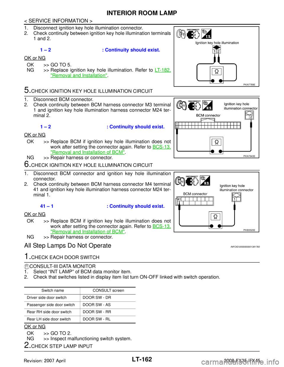
1. Disconnect ignition key hole illumination connector.
2. Check continuity between ignition key hole illumination terminals1 and 2.
OK or NG
OK >> GO TO 5.
NG >> Replace ignition key hole illumination. Refer to LT-182,
"Removal and Installation".
5.CHECK IGNITION KEY HOLE ILLUMINATION CIRCUIT
1. Disconnect BCM connector.
2. Check continuity between BCM harness connector M3 terminal 1 and ignition key hole illumination harness connector M24 ter-
minal 2.
OK or NG
OK >> Replace BCM if ignition key hole illumination does not work after setting the connector again. Refer to BCS-13,
"Removal and Installation of BCM".
NG >> Repair harness or connector.
6.CHECK IGNITION KEY HOLE ILLUMINATION CIRCUIT
1. Disconnect BCM connector and ignition key hole illumination connector.
2. Check continuity between BCM harness connector M4 terminal
41 and ignition key hole illumination harness connector M24 ter-
minal 1.
OK or NG
OK >> Replace BCM if ignition key hole illumination does not work after setting the connector again. Refer to BCS-13,
"Removal and Installation of BCM".
NG >> Repair harness or connector.
All Step Lamps Do Not OperateINFOID:0000000001381760
1.CHECK EACH DOOR SWITCH
CONSULT-III DATA MONITOR
1. Select “INT LAMP” of BCM data monitor item.
2. Check that switches listed in display item list turn ON-OFF linked with switch operation.
OK or NG
OK >> GO TO 2.
NG >> Inspect malfunctioning switch system.
2.CHECK STEP LAMP INPUT 1 – 2 : Continuity should exist.
PKIA7789E
1 – 2 : Continuity should exist.
PKIA7643E
41 – 1 : Continuity should exist.
PKIB3520E
Switch name CONSULT screen
Driver side door switch DOOR SW - DR
Passenger side door switch DOOR SW - AS
Rear RH side door switch DOOR SW - RR
Rear LH side door switch DOOR SW - RL
3AA93ABC3ACD3AC03ACA3AC03AC63AC53A913A773A893A873A873A8E3A773A983AC73AC93AC03AC3
3A893A873A873A8F3A773A9D3AAF3A8A3A8C3A863A9D3AAF3A8B3A8C
Page 3265 of 3924

INTERIOR ROOM LAMPLT-163
< SERVICE INFORMATION >
C
DE
F
G H
I
J
L
M A
B
LT
N
O P
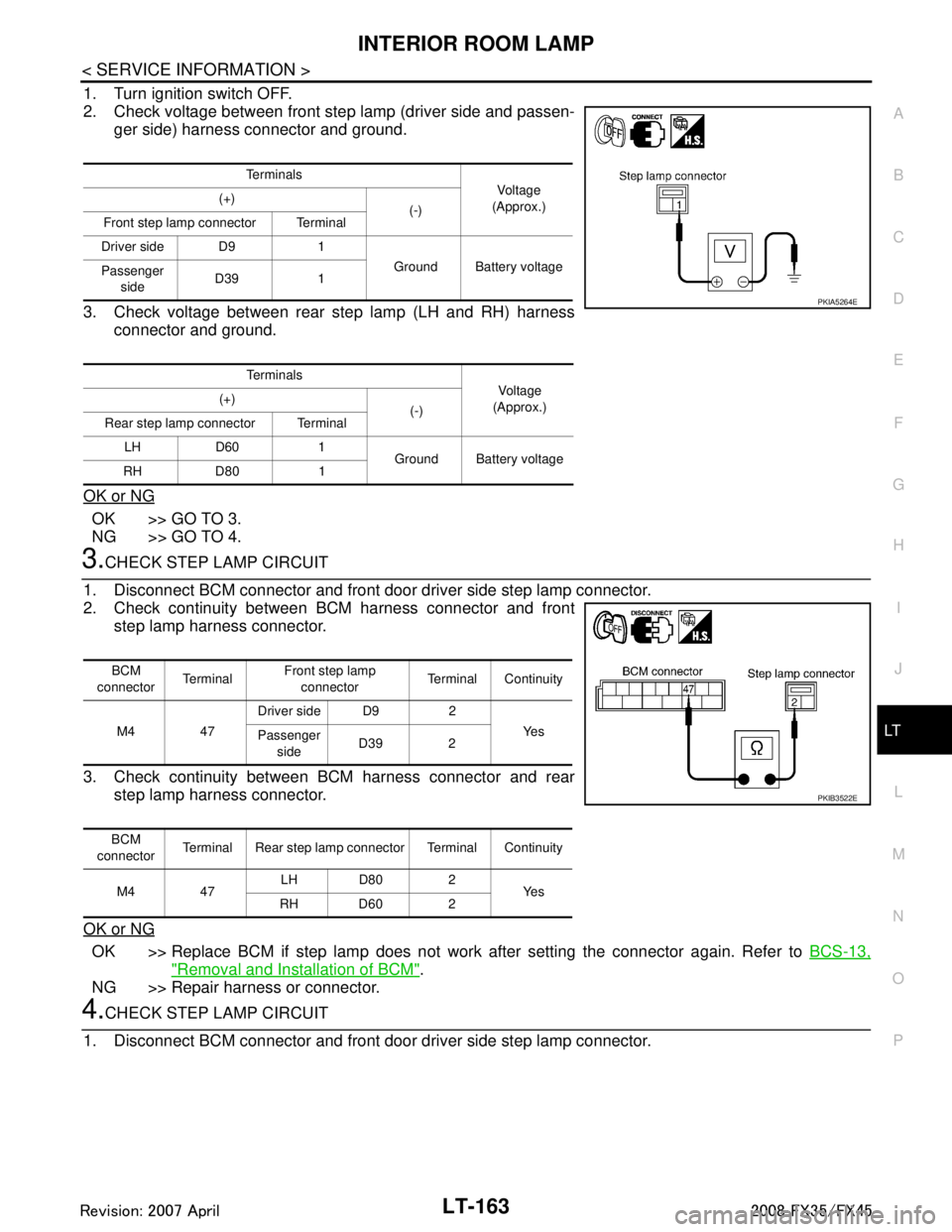
1. Turn ignition switch OFF.
2. Check voltage between front step lamp (driver side and passen- ger side) harness connector and ground.
3. Check voltage between rear step lamp (LH and RH) harness connector and ground.
OK or NG
OK >> GO TO 3.
NG >> GO TO 4.
3.CHECK STEP LAMP CIRCUIT
1. Disconnect BCM connector and front door driver side step lamp connector.
2. Check continuity between BCM harness connector and front step lamp harness connector.
3. Check continuity between BCM harness connector and rear step lamp harness connector.
OK or NG
OK >> Replace BCM if step lamp does not work after setting the connector again. Refer to BCS-13,
"Removal and Installation of BCM".
NG >> Repair harness or connector.
4.CHECK STEP LAMP CIRCUIT
1. Disconnect BCM connector and front door driver side step lamp connector.
Te r m i n a l s Vo l ta g e
(Approx.)
(+)
(-)
Front step lamp connector Terminal
Driver side D9 1 Ground Battery voltage
Passenger
side D39 1
Te r m i n a l s Voltag e
(Approx.)
(+)
(-)
Rear step lamp connector Terminal
LH D60 1 Ground Battery voltage
RH D80 1
PKIA5264E
BCM
connector Te r m i n a l Front step lamp
connector Terminal Continuity
M4 47 Driver side D9 2
Ye s
Passenger
side D39 2
BCM
connector Terminal Rear step lamp connector Terminal Continuity
M4 47 LH D80 2
Ye s
RH D60 2
PKIB3522E
3AA93ABC3ACD3AC03ACA3AC03AC63AC53A913A773A893A873A873A8E3A773A983AC73AC93AC03AC3
3A893A873A873A8F3A773A9D3AAF3A8A3A8C3A863A9D3AAF3A8B3A8C
Page 3266 of 3924

LT-164
< SERVICE INFORMATION >
INTERIOR ROOM LAMP
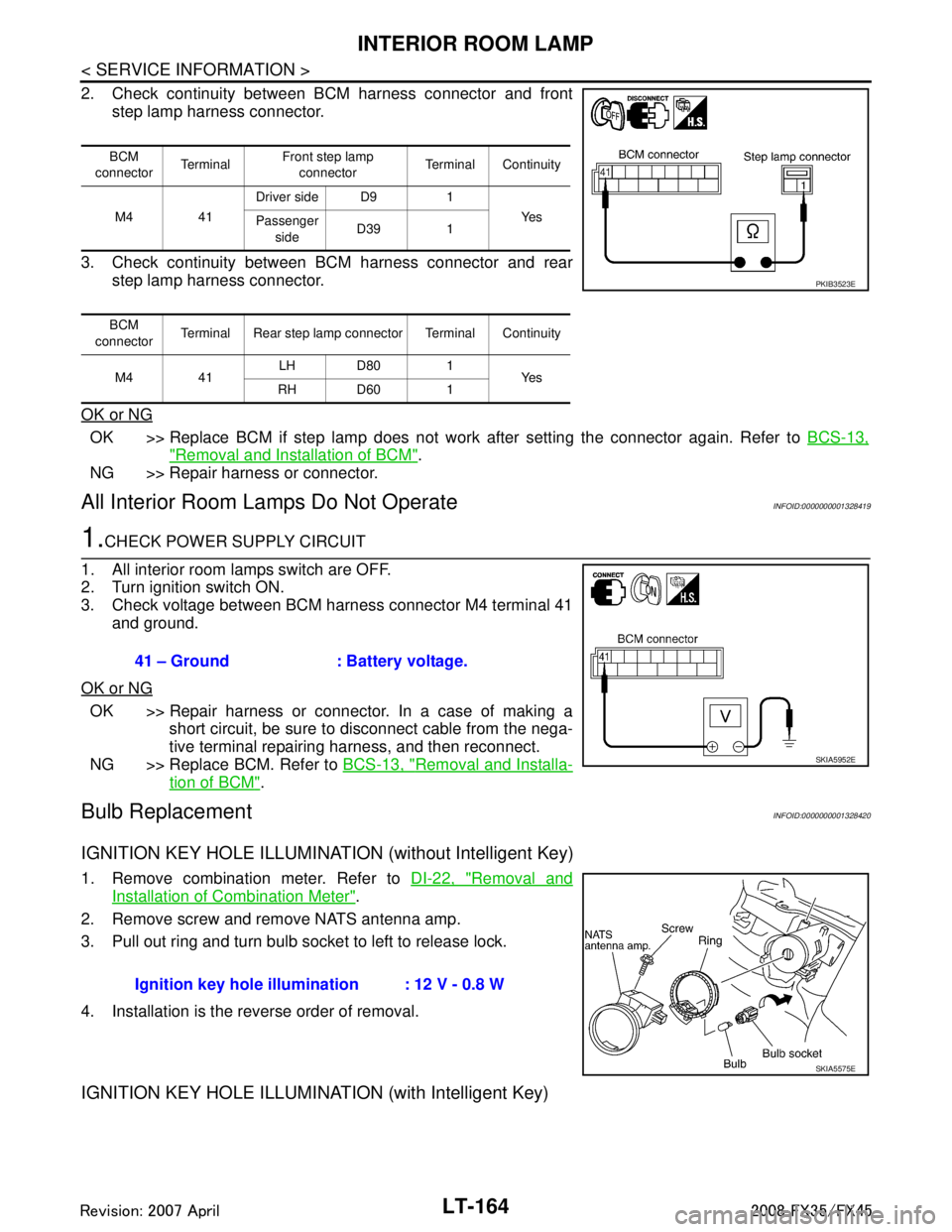
2. Check continuity between BCM harness connector and frontstep lamp harness connector.
3. Check continuity between BCM harness connector and rear step lamp harness connector.
OK or NG
OK >> Replace BCM if step lamp does not work after setting the connector again. Refer to BCS-13,
"Removal and Installation of BCM".
NG >> Repair harness or connector.
All Interior Room La mps Do Not OperateINFOID:0000000001328419
1.CHECK POWER SUPPLY CIRCUIT
1. All interior room lamps switch are OFF.
2. Turn ignition switch ON.
3. Check voltage between BCM harness connector M4 terminal 41 and ground.
OK or NG
OK >> Repair harness or connector. In a case of making a short circuit, be sure to disconnect cable from the nega-
tive terminal repairing harness, and then reconnect.
NG >> Replace BCM. Refer to BCS-13, "
Removal and Installa-
tion of BCM".
Bulb ReplacementINFOID:0000000001328420
IGNITION KEY HOLE ILLUMINATION (without Intelligent Key)
1. Remove combination meter. Refer to DI-22, "Removal and
Installation of Combination Meter".
2. Remove screw and remove NATS antenna amp.
3. Pull out ring and turn bulb socket to left to release lock.
4. Installation is the reverse order of removal.
IGNITION KEY HOLE ILLUMINA TION (with Intelligent Key)
BCM
connector Te r m i n a l Front step lamp
connector Terminal Continuity
M4 41 Driver side D9 1
Ye s
Passenger
side D39 1
BCM
connector Terminal Rear step lamp connector Terminal Continuity
M4 41 LH D80 1
Ye s
RH D60 1
PKIB3523E
41 – Ground : Battery voltage.
SKIA5952E
Ignition key hole illu mination : 12 V - 0.8 W
SKIA5575E
3AA93ABC3ACD3AC03ACA3AC03AC63AC53A913A773A893A873A873A8E3A773A983AC73AC93AC03AC3
3A893A873A873A8F3A773A9D3AAF3A8A3A8C3A863A9D3AAF3A8B3A8C
Page 3271 of 3924

ILLUMINATIONLT-169
< SERVICE INFORMATION >
C
DE
F
G H
I
J
L
M A
B
LT
N
O P
ILLUMINATION
System DescriptionINFOID:0000000001328422
Control of illumination lamps operation is dependent upon position of lighting switch (combination switch).
When lighting switch is placed in the 1ST or 2ND positi on (or if auto light system is activated), BCM (body con-
trol module) receives input signal requesting illuminati on lamps to illuminate. This input signal is communi-
cated to IPDM E/R (intelligent power distribution module engine room) through the CAN communication. The
CPU (central processing unit) located in the IPDM E/R co ntrols tail lamp relay coil. This relay, when energized,
directs power to illumination lamps, which then illuminate.
Power is supplied at all times
through 10A fuse (No. 71, located in IPDM E/R)
to tail lamp relay, located in IPDM E/R, and
to CPU located in IPDM E/R.
Power is also supplied at all times
through 50A fusible link (letter M, located in fuse, fusible link and relay box)
to BCM terminal 55,
through 15A fuse [No. 22 located in fuse block (J/B)]
to BCM terminal 42,
through 15A fuse (No. 78, located in IPDM E/R)
to CPU located in IPDM E/R,
through 10A fuse [No. 19 located in fuse block (J/B)]
to unified meter and A/C amp. terminal 21 and
to combination meter terminal 8.
With ignition switch in ON or START position, power is supplied
to ignition relay, located in IPDM E/R, from battery direct,
through 15A fuse [No. 1 located in fuse block (J/B)]
to BCM terminal 38,
through 10A fuse [No. 12, located in fuse block (J/B)]
to unified meter and A/C amp. terminal 22 and
to combination meter terminal 7.
With ignition switch in ACC or ON position, power is supplied
through 10A fuse [No. 6, located in fuse block (J/B)]
to combination meter terminal 4 and
to BCM terminal 11.
Ground is supplied
to BCM terminals 49 and 52
to unified meter and A/C amp. terminals 29 and 30, and
to combination meter terminals 5, 6, and 15
through grounds M35, M45, and M85,
to IPDM E/R terminals 38 and 60
through grounds E21, E50, and E51.
ILLUMINATION OPERATION BY LIGHTING SWITCH
With lighting switch in the 1ST or 2ND position (or if auto light system is activated), BCM receives input signal
requesting illumination lamps to illuminate. This input signal is communicated to IPDM E/R through the CAN
communication. The CPU located in the IPDM E/R controls tail lamp relay coil, which, when energized, directs
power
through IPDM E/R terminal 22
to glove box lamp terminal 1
to A/T device (illumination) terminal 11
to snow mode switch (illumination) terminal 5
to VDC off switch (illumination) terminal 3
to clock (illumination) terminal 3
to hazard switch (illumination) terminal 3
to heated seat switch (driver side) (illumination) terminal 5
to heated seat switch (passenger side) (illumination) terminal 5
to door mirror remote control switch (illumination) terminal 16
to LDW switch (illumination) terminal 5
to combination switch (spiral cable) terminal 26
to microphone terminal 2 (with telephone system)
3AA93ABC3ACD3AC03ACA3AC03AC63AC53A913A773A893A873A873A8E3A773A983AC73AC93AC03AC3
3A893A873A873A8F3A773A9D3AAF3A8A3A8C3A863A9D3AAF3A8B3A8C
Page 3272 of 3924

LT-170
< SERVICE INFORMATION >
ILLUMINATION
to A/C and AV switch (illumination) terminal 3
to DVD player (illumination) terminal 12
to coin box illumination terminal 2 and
to rear power window switch LH and RH (illumination) terminals 6,
through combination switch (spiral cable) terminal 18
to audio steering switch (illumination)
to icc steering switch (illumination) (with icc) and
to ascd steering switch (illumination) (without icc)
Illumination control
through combination meter terminal 19
to A/T device (illumination) terminal 12
to snow mode switch (illumination) terminal 6
to VDC off switch (illumination) terminal 4
to clock (illumination) terminal 4
to hazard switch (illumination) terminal 4
to heated seat switch (driver side) (illumination) terminal 6
to heated seat switch (passenger side) (illumination) terminal 6
to door mirror remote control switch terminal 15
to LDW switch (illumination) terminal 4,
to combination switch (spiral cable) terminal 27
to A/C and AV switch (illumination) terminal 4 and
to DVD player (illumination) terminal 10,
through combination switch (spiral cable) terminal 21
to audio steering switch (illumination)
to icc steering switch (illumination) (with icc) and
to ascd steering switch (illumination) (without icc)
Ground is supplied at all times
to glove box lamp terminal 2 and
to coin box illumination terminal 3
through grounds M35, M45 and M85,
to rear power window switch LH and RH (illumination) terminals 7
through grounds B15 and B45.
With power and ground supplied, illumination lamps illuminate.
EXTERIOR LAMP BATTERY SAVER CONTROL
When the lighting switch is in the 1ST or 2ND position (or if auto light system is activated), and ignition switch
is turned from ON or ACC to OFF, batte ry saver control function is activated.
Under this condition, illumination lamps remain illuminated for 5 minutes, then illumination lamps are turned
off.
When the lighting switch is turned from OFF to 1ST or 2 ND position (or if auto light system is activated) after
illumination lamps are turned off by battery save r control, and illumination lamps illuminate again.
Exterior lamp battery saver control mode can be changed by the function setting of CONSULT-III.
CAN Communication System DescriptionINFOID:0000000001328423
CAN (Controller Area Network) is a serial communication line for real time application. It is an on-vehicle mul-
tiplex communication line with high data communication s peed and excellent error detection ability. Many elec-
tronic control units are equipped onto a vehicle, and each control unit shares information and links with other
control units during operation (not independent). In CA N communication, control units are connected with 2
communication lines (CAN H line, CAN L line) allowing a high rate of information transmission with less wiring.
Each control unit transmits/receives data but selectively reads required data only.
CAN Communication UnitINFOID:0000000001328424
Refer to LAN-43, "CAN System Specification Chart".
3AA93ABC3ACD3AC03ACA3AC03AC63AC53A913A773A893A873A873A8E3A773A983AC73AC93AC03AC3
3A893A873A873A8F3A773A9D3AAF3A8A3A8C3A863A9D3AAF3A8B3A8C
Page 3381 of 3924

IPDM E/R (INTELLIGENT POWER DISTRIBUTION MODULE ENGINE ROOM)
PG-17
< SERVICE INFORMATION >
C
D E
F
G H
I
J
L
M A
B
PG
N
O P
IPDM E/R (INTELLIGENT POWER DISTRIBUTION MODULE ENGINE
ROOM)
System DescriptionINFOID:0000000001328870
IPDM E/R (Intelligent Power Distribution Module Engi ne Room) integrates the relay box and fuse block
which were originally placed in engine compartment. It c ontrols integrated relay via IPDM E/R control circuit.
IPDM E/R-integrated control circuit performs ON-OFF operation of relay, CAN communication control, oil
pressure switch signal, and hood switch signal reception, etc.
It controls operation of each electrical pa rt via ECM, BCM and CAN communication lines.
CAUTION:
None of the IPDM E/R-integr ated relays can be removed.
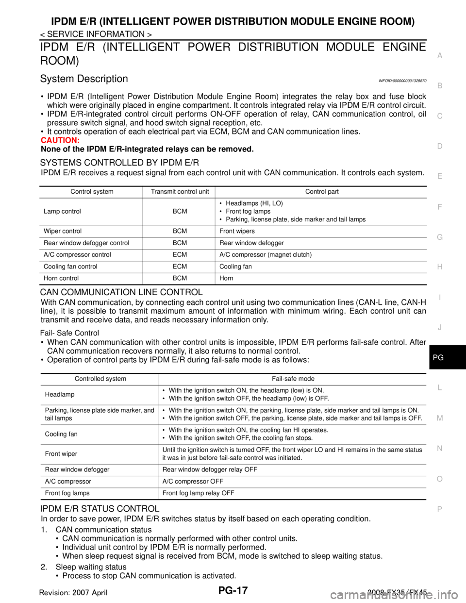
SYSTEMS CONTROLLED BY IPDM E/R
IPDM E/R receives a request signal fr om each control unit with CAN communication. It controls each system.
CAN COMMUNICATION LINE CONTROL
With CAN communication, by connecting each control uni t using two communication lines (CAN-L line, CAN-H
line), it is possible to transmit maximum amount of in formation with minimum wiring. Each control unit can
transmit and receive data, and reads necessary information only.
Fail- Safe Control
When CAN communication with other control units is impos sible, IPDM E/R performs fail-safe control. After
CAN communication recovers normally, it also returns to normal control.
Operation of control parts by IPDM E/R during fail-safe mode is as follows:
IPDM E/R STATUS CONTROL
In order to save power, IPDM E/R switches status by itself based on each operating condition.
1. CAN communication status CAN communication is normally performed with other control units.
Individual unit control by IPDM E/R is normally performed.
When sleep request signal is received from BCM, mode is switched to sleep waiting status.
2. Sleep waiting status Process to stop CAN communication is activated.
Control system Transmit control unit Control part
Lamp control BCM Headlamps (HI, LO)
Front fog lamps
Parking, license plate, side marker and tail lamps
Wiper control BCM Front wipers
Rear window defogger control BCM Rear window defogger
A/C compressor control ECM A/C compressor (magnet clutch)
Cooling fan control ECM Cooling fan
Horn control BCM Horn
Controlled system Fail-safe mode
Headlamp With the ignition switch ON, the headlamp (low) is ON.
With the ignition switch OFF, the headlamp (low) is OFF.
Parking, license plate side marker, and
tail lamps With the ignition switch ON, the parking, license plate, side marker and tail lamps is ON.
With the ignition switch OFF, the parking, license plate, side marker and tail lamps is OFF.
Cooling fan With the ignition switch ON, the cooling fan HI operates.
With the ignition switch OFF, the cooling fan stops.
Front wiper Until the ignition switch is turned OFF, the front wiper LO and HI remains in the same status
it was in just before fail-safe control was initiated.
Rear window defogger Rear window defogger relay OFF
A/C compressor A/C compressor OFF
Front fog lamps Front fog lamp relay OFF
3AA93ABC3ACD3AC03ACA3AC03AC63AC53A913A773A893A873A873A8E3A773A983AC73AC93AC03AC3
3A893A873A873A8F3A773A9D3AAF3A8A3A8C3A863A9D3AAF3A8B3A8C
Page 3382 of 3924

PG-18
< SERVICE INFORMATION >
IPDM E/R (INTELLIGENT POWER DISTRIBUTION MODULE ENGINE ROOM)
All systems controlled by IPDM E/R are stopped. When 3 seconds have elapsed after CAN communica-
tion with other control units is st opped, mode switches to sleep status.
3. Sleep status IPDM E/R operates in low power mode.
CAN communication is stopped.
When a change in CAN communication line is detected, mode switches to CAN communication status.
When a change hood switch or ignition switch signal is detected, mode switches to CAN communication
status.
CAN Communication System DescriptionINFOID:0000000001328871
CAN (Controller Area Network) is a serial communication line for real time application. It is an on-vehicle mul-
tiplex communication line with high data communication speed and excellent error detection ability. Modern
vehicles are equipped with many electronic control units and each control unit shares information and links
with other control units during operation (not independent ). In CAN communication, control units are con-
nected with 2 communication lines (CAN-H line, CAN-L line) allowing a high rate of information transmission
with less wiring. Each control unit transmits/recei ves data but selectively reads required data only.
CAN Communication UnitINFOID:0000000001328872
Refer to LAN-43, "CAN System Specification Chart".
Function of Detecting I gnition Relay MalfunctionINFOID:0000000001328873
When contact point of integrated ignition relay is st uck and cannot be turned OFF, IPDM E/R turns ON park-
ing, license plate, side marker and tail lamps for 10 minutes to indicate ignition relay malfunction.
When a state of ignition relay having built-in does not agr ee with a state of ignition switch signal input by a
CAN communication from BCM, IPDM E/R lets tail lamp relay operate.
NOTE:
When the ignition switch is turned ON, the tail lamps are OFF.
CONSULT-III Function (IPDM E/R)INFOID:0000000001328874
CONSULT-III can display each diagnostic item using the diagnostic test mode shown following.
Self Diagnostic Result
Display Item List
Ignition switch signal Ignition relay status Tail lamp relay
ON ON —
OFF OFF — ON OFF —
OFF ON ON (10 minutes)
Inspection Item, Diagnosis Mode Description
Self Diagnostic Result The IPDM E/R performs diagnosis of the CAN communication and self-diagnosis.
Data Monitor The input/output data of the IPDM E/R is displayed in real time.
CAN Diag Support Monitor The result of transmit/receive diagnosis of CAN communication can be read.
Active test The IPDM E/R sends a drive signal to electronic components to check their operation.
3AA93ABC3ACD3AC03ACA3AC03AC63AC53A913A773A893A873A873A8E3A773A983AC73AC93AC03AC3
3A893A873A873A8F3A773A9D3AAF3A8A3A8C3A863A9D3AAF3A8B3A8C
Page 3383 of 3924

IPDM E/R (INTELLIGENT POWER DISTRIBUTION MODULE ENGINE ROOM)
PG-19
< SERVICE INFORMATION >
C
D E
F
G H
I
J
L
M A
B
PG
N
O P
NOTE: The details for display of the period are as follows:
CRNT: Error currently de tected with IPDM E/R.
PAST: Error detected in the past and memorized with IPDM E/R.
DATA MONITOR
NOTE:
Perform monitoring of IPDM E/R data with the ignition switch ON. When the ignition switch is at ACC, the display may not be co rrect.
*1: The vehicle without the Intelligent Key system displays only ON without change.
*2:The cornering lamp item is displayed, but it cannot be monitored.
ACTIVE TEST
DTC Display Items Malfunction detecting condition TIME
Possible causes
CRNT PAST
— NO DTC IS DETECT-
ED.FURTHER TEST-
ING MAY BE
REQUIRED. ————
U1000 CAN COMM CIRCUIT If CAN communication reception/transmission
data has a malfunction, or if any of the control
units malfunction, data reception/transmission
cannot be confirmed.
When the data in CAN communication is not re- ceived before the specified time ××
Any of or several items
below have errors.
TRANSMIT DIAG
ECM
BCM/SEC
Item name
CONSULT-III screen dis-
play Display or unit MAIN SIG-
NALS Description
Motor fan request MOTOR FAN REQ 1/2/3/4 ×Signal status input from ECM
Compressor request A C COMP REQ On/Off ×Signal status input from ECM
Tail & clear request TAIL&CLR REQ On/Off ×Signal status input from BCM
H/L LO request HL LO REQ On/Off ×Signal status input from BCM
H/L HI request HL HI REQ On/Off ×Signal status input from BCM
FR fog request FR FOG REQ On/Off ×Signal status input from BCM
FR wiper request FR WIP REQ Stop/1LOW/Lo/Hi ×Signal status input from BCM
Wiper auto stop WIP AUTO STOP ACT P/STOP P ×Output status of IPDM E/R
Wiper protection WIP PROT Off/BLOCK ×Control status of IPDM E/R
Starter request ST RLY REQ
*1On/Off Status of input signal
Ignition relay status IGN RLY On/Off ×Ignition relay status monitored with
IPDM E/R
Rear window defogger re-
quest RR DEF REQ On/Off
×Signal status input from BCM
Oil pressure switch OIL P SW Open/Close Signal status input in IPDM E/R
Hood switch HOOD SW On/Off Input signal status
Theft warning horn re-
quest THFT HRN REQ On/Off Signal st
atus input from BCM
Horn chirp HORN CHIRP On/Off Ou tput status of IPDM E/R
Cornering lamp request CRNRNG LMP REQ
*2Off Signal status input from BCM
Test item CONSULT-III screen display Description
Tail lamp operation TAIL LAMP With a certain On-Off operation, the tail lamp relay can be operated.
Rear window defogger opera-
tion REAR DEFOGGER
With a certain On-Off operation, the rear window defogger relay can be
operated.
3AA93ABC3ACD3AC03ACA3AC03AC63AC53A913A773A893A873A873A8E3A773A983AC73AC93AC03AC3
3A893A873A873A8F3A773A9D3AAF3A8A3A8C3A863A9D3AAF3A8B3A8C