2008 INFINITI FX35 ignition
[x] Cancel search: ignitionPage 2949 of 3924
GW-36
< SERVICE INFORMATION >
POWER WINDOW SYSTEM
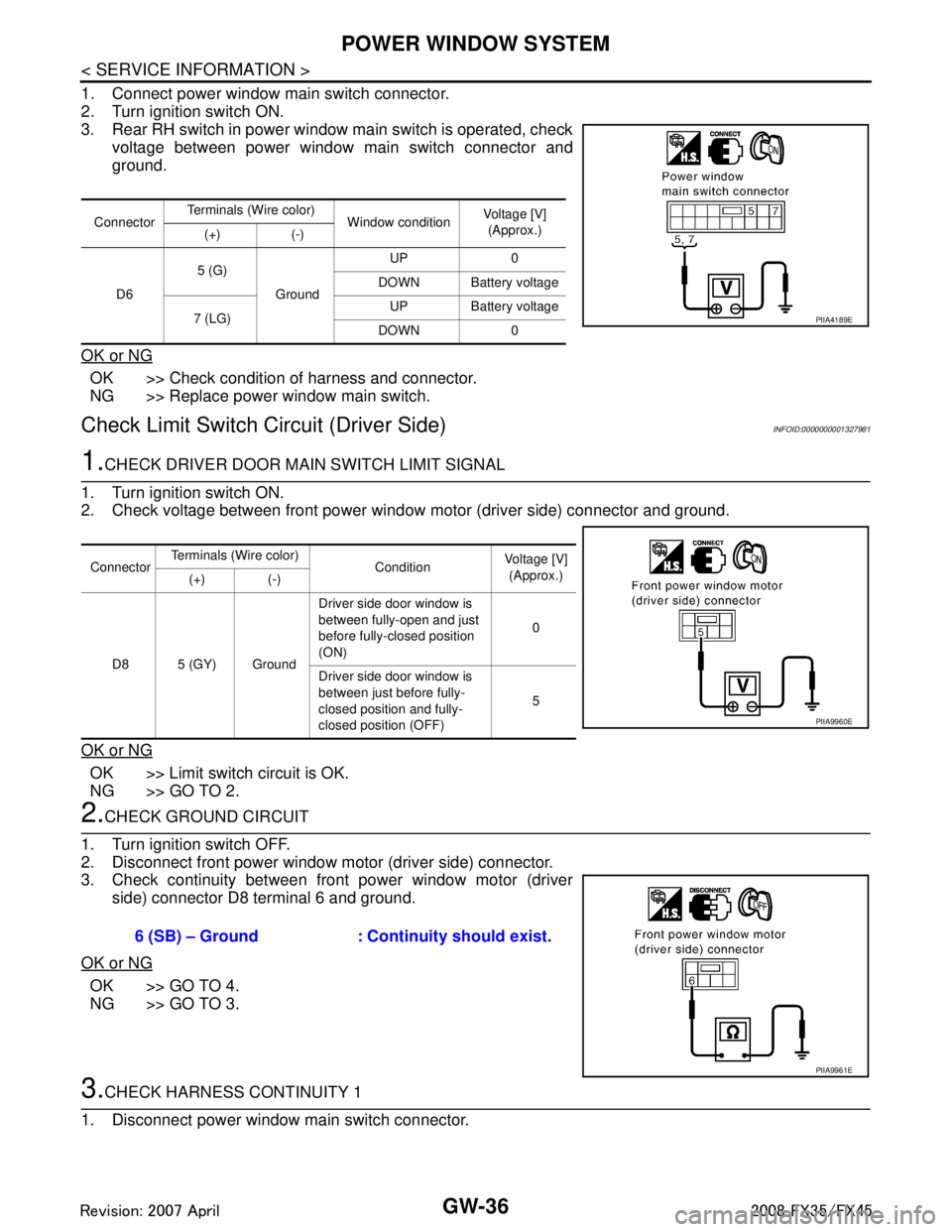
1. Connect power window main switch connector.
2. Turn ignition switch ON.
3. Rear RH switch in power window main switch is operated, checkvoltage between power window main switch connector and
ground.
OK or NG
OK >> Check condition of harness and connector.
NG >> Replace power window main switch.
Check Limit Switch Circuit (Driver Side)INFOID:0000000001327981
1.CHECK DRIVER DOOR MAIN SWITCH LIMIT SIGNAL
1. Turn ignition switch ON.
2. Check voltage between front power window motor (driver side) connector and ground.
OK or NG
OK >> Limit switch circuit is OK.
NG >> GO TO 2.
2.CHECK GROUND CIRCUIT
1. Turn ignition switch OFF.
2. Disconnect front power window motor (driver side) connector.
3. Check continuity between front power window motor (driver side) connector D8 terminal 6 and ground.
OK or NG
OK >> GO TO 4.
NG >> GO TO 3.
3.CHECK HARNESS CONTINUITY 1
1. Disconnect power window main switch connector.
Connector Terminals (Wire color)
Window conditionVoltage [V]
(Approx.)
(+) (-)
D6 5 (G)
Ground UP 0
DOWN Battery voltage
7 (LG) UP Battery voltage
DOWN 0
PIIA4189E
Connector Terminals (Wire color)
Condition Voltage [V]
(Approx.)
(+) (-)
D8 5 (GY) Ground Driver side door window is
between fully-open and just
before fully-closed position
(ON)
0
Driver side door window is
between just before fully-
closed position and fully-
closed position (OFF) 5
PIIA9960E
6 (SB) – Ground : Continuity should exist.
PIIA9961E
3AA93ABC3ACD3AC03ACA3AC03AC63AC53A913A773A893A873A873A8E3A773A983AC73AC93AC03AC3
3A893A873A873A8F3A773A9D3AAF3A8A3A8C3A863A9D3AAF3A8B3A8C
Page 2950 of 3924
POWER WINDOW SYSTEMGW-37
< SERVICE INFORMATION >
C
DE
F
G H
J
K L
M A
B
GW
N
O P
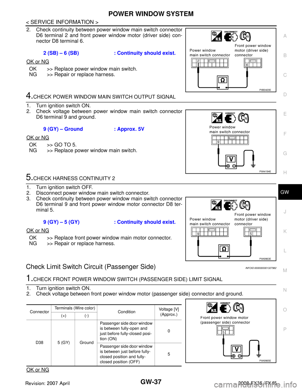
2. Check continuity between power window main switch connector D6 terminal 2 and front power window motor (driver side) con-
nector D8 terminal 6.
OK or NG
OK >> Replace power window main switch.
NG >> Repair or replace harness.
4.CHECK POWER WINDOW MAIN SWITCH OUTPUT SIGNAL
1. Turn ignition switch ON.
2. Check voltage between power window main switch connector D6 terminal 9 and ground.
OK or NG
OK >> GO TO 5.
NG >> Replace power window main switch.
5.CHECK HARNESS CONTINUITY 2
1. Turn ignition switch OFF.
2. Disconnect power window main switch connector.
3. Check continuity between power window main switch connector D6 terminal 9 and front power window motor connector D8 ter-
minal 5.
OK or NG
OK >> Replace front power window main motor connector.
NG >> Repair or replace harness.
Check Limit Switch Ci rcuit (Passenger Side)INFOID:0000000001327982
1.CHECK FRONT POWER WINDOW SWITCH (PASSENGER SIDE) LIMIT SIGNAL
1. Turn ignition switch ON.
2. Check voltage between front power window motor (passenger side) connector and ground.
OK or NG
2 (SB) – 6 (SB) : Cont inuity should exist.
PIIB0420E
9 (GY) – Ground : Approx. 5V
PIIA4194E
9 (GY) – 5 (GY) : Continuity should exist.
PIIA9963E
ConnectorTerminals (Wire color)
Condition Voltage [V]
(Approx.)
(+) (-)
D38 5 (GY) Ground Passenger side door window
is between fully-open and
just before fully-closed posi-
tion (ON)
0
Passenger side door window
is between just before fully-
closed position and fully-
closed position (OFF) 5
PIIA9965E
3AA93ABC3ACD3AC03ACA3AC03AC63AC53A913A773A893A873A873A8E3A773A983AC73AC93AC03AC3
3A893A873A873A8F3A773A9D3AAF3A8A3A8C3A863A9D3AAF3A8B3A8C
Page 2951 of 3924
GW-38
< SERVICE INFORMATION >
POWER WINDOW SYSTEM
OK >> Limit switch circuit is OK.
NG >> GO TO 2.
2.CHECK GROUND CIRCUIT
1. Turn ignition switch OFF.
2. Disconnect front power window motor (passenger side) connector.
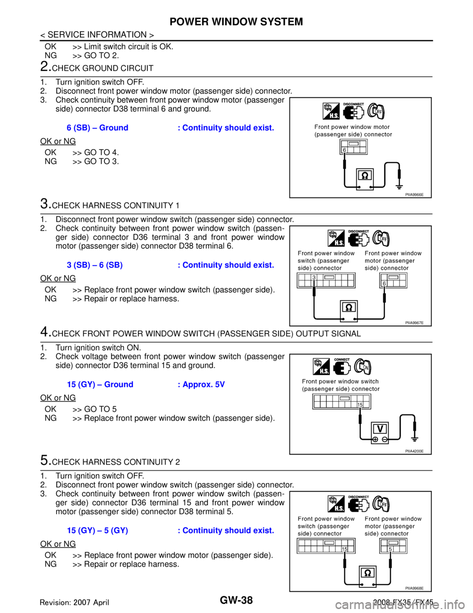
3. Check continuity between front power window motor (passenger side) connector D38 terminal 6 and ground.
OK or NG
OK >> GO TO 4.
NG >> GO TO 3.
3.CHECK HARNESS CONTINUITY 1
1. Disconnect front power window switch (passenger side) connector.
2. Check continuity between front power window switch (passen- ger side) connector D36 terminal 3 and front power window
motor (passenger side) connector D38 terminal 6.
OK or NG
OK >> Replace front power window switch (passenger side).
NG >> Repair or replace harness.
4.CHECK FRONT POWER WINDOW SWITCH (P ASSENGER SIDE) OUTPUT SIGNAL
1. Turn ignition switch ON.
2. Check voltage between front power window switch (passenger side) connector D36 terminal 15 and ground.
OK or NG
OK >> GO TO 5
NG >> Replace front power window switch (passenger side).
5.CHECK HARNESS CONTINUITY 2
1. Turn ignition switch OFF.
2. Disconnect front power window switch (passenger side) connector.
3. Check continuity between front power window switch (passen- ger side) connector D36 terminal 15 and front power window
motor (passenger side) connector D38 terminal 5.
OK or NG
OK >> Replace front power window motor (passenger side).
NG >> Repair or replace harness. 6 (SB) – Ground : Continuity should exist.
PIIA9966E
3 (SB) – 6 (SB) : Continuity should exist.
PIIA9967E
15 (GY) – Ground : Approx. 5V
PIIA4200E
15 (GY) – 5 (GY) : Cont
inuity should exist.
PIIA9968E
3AA93ABC3ACD3AC03ACA3AC03AC63AC53A913A773A893A873A873A8E3A773A983AC73AC93AC03AC3
3A893A873A873A8F3A773A9D3AAF3A8A3A8C3A863A9D3AAF3A8B3A8C
Page 2952 of 3924
POWER WINDOW SYSTEMGW-39
< SERVICE INFORMATION >
C
DE
F
G H
J
K L
M A
B
GW
N
O P
Check Encoder Circ uit (Driver Side)INFOID:0000000001327983
1.CHECK FRONT POWER WINDOW MOTO R (DRIVER SIDE) POWER SUPPLY
1. Turn ignition switch ON.
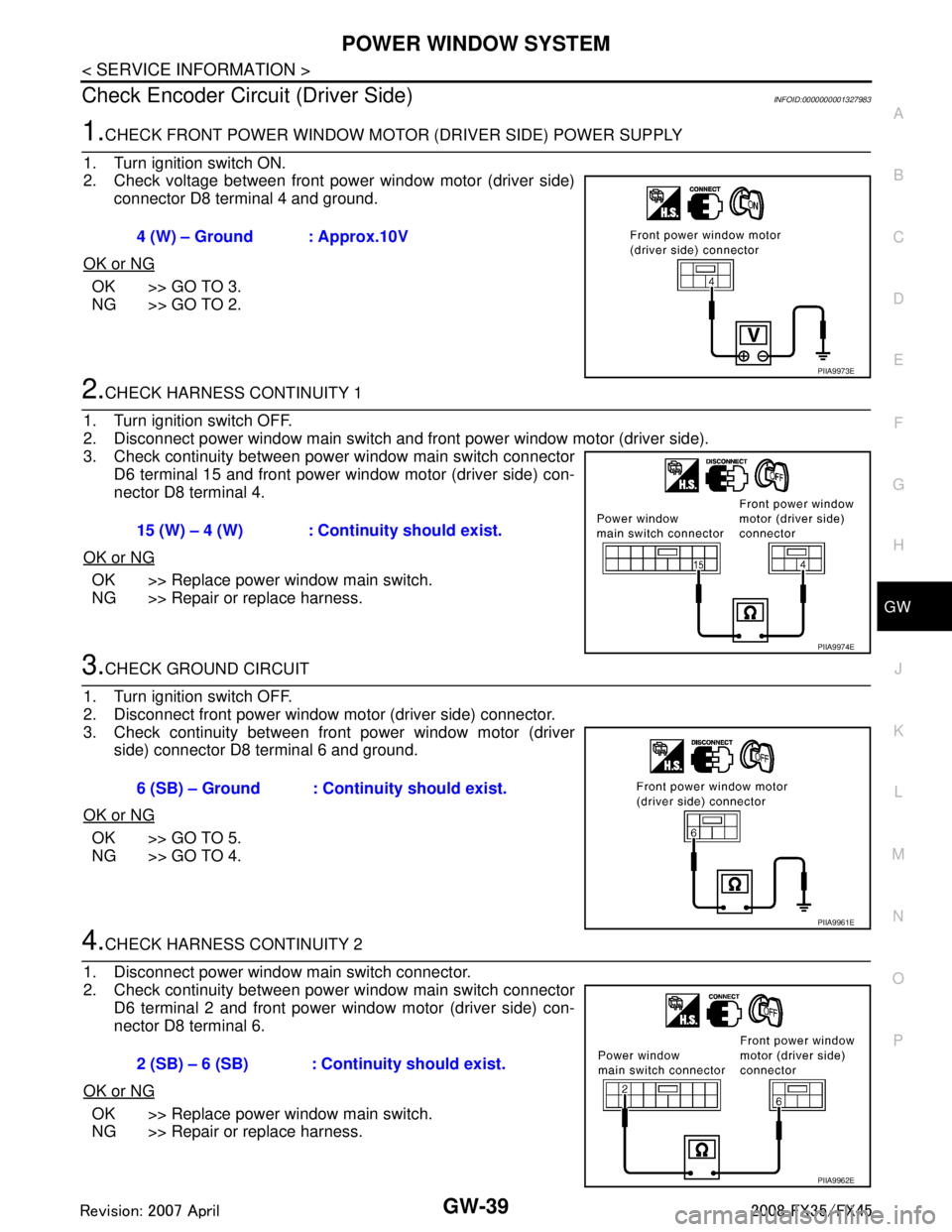
2. Check voltage between front power window motor (driver side) connector D8 terminal 4 and ground.
OK or NG
OK >> GO TO 3.
NG >> GO TO 2.
2.CHECK HARNESS CONTINUITY 1
1. Turn ignition switch OFF.
2. Disconnect power window main switch and front power window motor (driver side).
3. Check continuity between power window main switch connector D6 terminal 15 and front power window motor (driver side) con-
nector D8 terminal 4.
OK or NG
OK >> Replace power window main switch.
NG >> Repair or replace harness.
3.CHECK GROUND CIRCUIT
1. Turn ignition switch OFF.
2. Disconnect front power window motor (driver side) connector.
3. Check continuity between front power window motor (driver side) connector D8 terminal 6 and ground.
OK or NG
OK >> GO TO 5.
NG >> GO TO 4.
4.CHECK HARNESS CONTINUITY 2
1. Disconnect power window main switch connector.
2. Check continuity between power window main switch connector D6 terminal 2 and front power window motor (driver side) con-
nector D8 terminal 6.
OK or NG
OK >> Replace power window main switch.
NG >> Repair or replace harness. 4 (W) – Ground : Approx.10V
PIIA9973E
15 (W) – 4 (W) : Continuity should exist.
PIIA9974E
6 (SB) – Ground : Continuity should exist.
PIIA9961E
2 (SB) – 6 (SB) : Continuity should exist.
PIIA9962E
3AA93ABC3ACD3AC03ACA3AC03AC63AC53A913A773A893A873A873A8E3A773A983AC73AC93AC03AC3
3A893A873A873A8F3A773A9D3AAF3A8A3A8C3A863A9D3AAF3A8B3A8C
Page 2953 of 3924
GW-40
< SERVICE INFORMATION >
POWER WINDOW SYSTEM
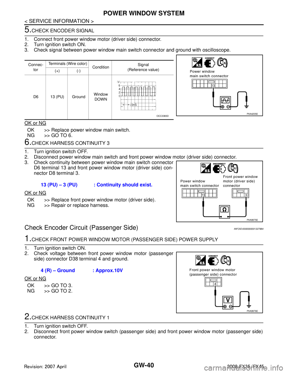
5.CHECK ENCODER SIGNAL
1. Connect front power window motor (driver side) connector.
2. Turn ignition switch ON.
3. Check signal between power window main switch connector and ground with oscilloscope.
OK or NG
OK >> Replace power window main switch.
NG >> GO TO 6.
6.CHECK HARNESS CONTINUITY 3
1. Turn ignition switch OFF.
2. Disconnect power window main switch and front power window motor (driver side) connector.
3. Check continuity between power window main switch connector D6 terminal 13 and front power window motor (driver side) con-
nector D8 terminal 3.
OK or NG
OK >> Replace front power window motor (driver side).
NG >> Repair or replace harness.
Check Encoder Circuit (Passenger Side)INFOID:0000000001327984
1.CHECK FRONT POWER WINDOW MOTOR (PASSENGER SIDE) POWER SUPPLY
1. Turn ignition switch ON.
2. Check voltage between front power window motor (passenger side) connector D38 terminal 4 and ground.
OK or NG
OK >> GO TO 3.
NG >> GO TO 2.
2.CHECK HARNESS CONTINUITY 1
1. Turn ignition switch OFF.
2. Disconnect front power window switch (passenger side) and front power window motor (passenger side) connector.
Connec-
tor Terminals (Wire color)
Condition Signal
(Reference value)
(+) (-)
D6 13 (PU) Ground Window
DOWN
PIIA4205EOCC3383D
13 (PU) – 3 (PU) : Continuity should exist.
PIIA9975E
4 (R) – Ground : Approx.10V
PIIA9976E
3AA93ABC3ACD3AC03ACA3AC03AC63AC53A913A773A893A873A873A8E3A773A983AC73AC93AC03AC3
3A893A873A873A8F3A773A9D3AAF3A8A3A8C3A863A9D3AAF3A8B3A8C
Page 2954 of 3924
POWER WINDOW SYSTEMGW-41
< SERVICE INFORMATION >
C
DE
F
G H
J
K L
M A
B
GW
N
O P
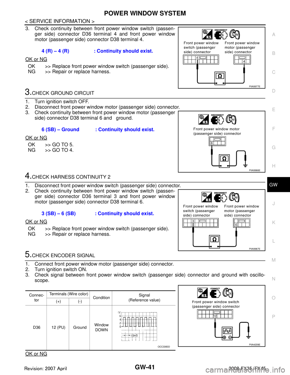
3. Check continuity between front power window switch (passen- ger side) connector D36 terminal 4 and front power window
motor (passenger side) connector D38 terminal 4.
OK or NG
OK >> Replace front power window switch (passenger side).
NG >> Repair or replace harness.
3.CHECK GROUND CIRCUIT
1. Turn ignition switch OFF.
2. Disconnect front power window motor (passenger side) connector.
3. Check continuity between front power window motor (passenger side) connector D38 terminal 6 and ground.
OK or NG
OK >> GO TO 5.
NG >> GO TO 4.
4.CHECK HARNESS CONTINUITY 2
1. Disconnect front power window switch (passenger side) connector.
2. Check continuity between front power window switch (passen- ger side) connector D36 terminal 3 and front power window
motor (passenger side) connector D38 terminal 6.
OK or NG
OK >> Replace front power window switch (passenger side).
NG >> Repair or replace harness.
5.CHECK ENCODER SIGNAL
1. Connect front power window motor (passenger side) connector.
2. Turn ignition switch ON.
3. Check signal between front power window switch (passenger side) connector and ground with oscillo-
scope.
OK or NG
4 (R) – 4 (R) : Continuity should exist.
PIIA9977E
6 (SB) – Ground : Continuity should exist.
PIIA9966E
3 (SB) – 6 (SB) : Continuity should exist.
PIIA9967E
Connec- tor Terminals (Wire color)
Condition Signal
(Reference value)
(+) (-)
D36 12 (PU) Ground Window
DOWN
PIIA4209EOCC3383D
3AA93ABC3ACD3AC03ACA3AC03AC63AC53A913A773A893A873A873A8E3A773A983AC73AC93AC03AC3
3A893A873A873A8F3A773A9D3AAF3A8A3A8C3A863A9D3AAF3A8B3A8C
Page 2955 of 3924
GW-42
< SERVICE INFORMATION >
POWER WINDOW SYSTEM
OK >> Replace front power window switch (passenger side).
NG >> GO TO 6.
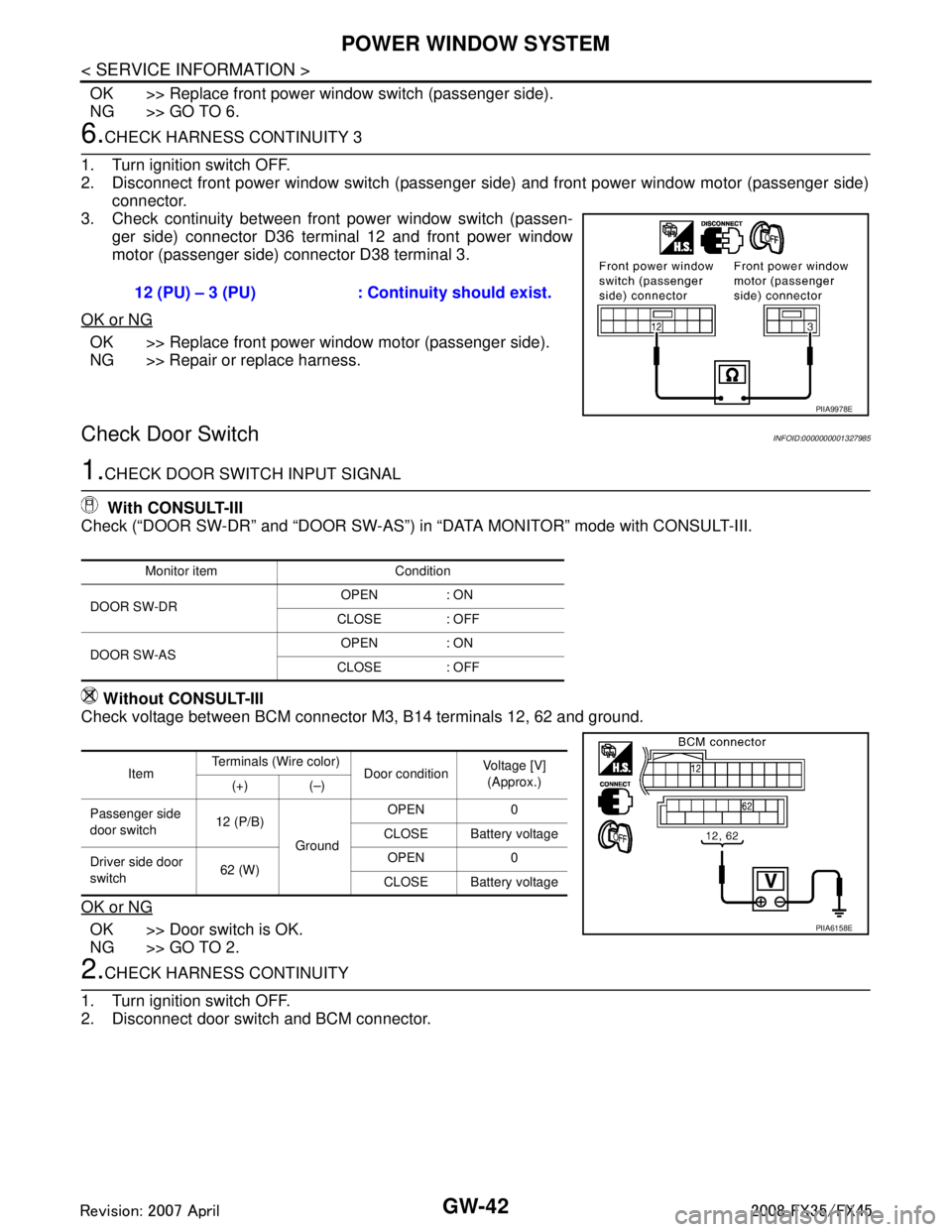
6.CHECK HARNESS CONTINUITY 3
1. Turn ignition switch OFF.
2. Disconnect front power window switch (passenger side) and front power window motor (passenger side) connector.
3. Check continuity between front power window switch (passen- ger side) connector D36 terminal 12 and front power window
motor (passenger side) connector D38 terminal 3.
OK or NG
OK >> Replace front power window motor (passenger side).
NG >> Repair or replace harness.
Check Door SwitchINFOID:0000000001327985
1.CHECK DOOR SWITCH INPUT SIGNAL
With CONSULT-III
Check (“DOOR SW-DR” and “DOOR SW-AS”) in “DATA MONITOR” mode with CONSULT-III.
Without CONSULT-III
Check voltage between BCM connector M3, B14 terminals 12, 62 and ground.
OK or NG
OK >> Door switch is OK.
NG >> GO TO 2.
2.CHECK HARNESS CONTINUITY
1. Turn ignition switch OFF.
2. Disconnect door switch and BCM connector. 12 (PU) – 3 (PU) : Continuity should exist.
PIIA9978E
Monitor item Condition
DOOR SW-DR OPEN : ON
CLOSE : OFF
DOOR SW-AS OPEN : ON
CLOSE : OFF
Item Terminals (Wire color)
Door conditionVoltage [V]
(Approx.)
(+) (–)
Passenger side
door switch 12 (P/B)
Ground OPEN 0
CLOSE Battery voltage
Driver side door
switch 62 (W) OPEN 0
CLOSE Battery voltage
PIIA6158E
3AA93ABC3ACD3AC03ACA3AC03AC63AC53A913A773A893A873A873A8E3A773A983AC73AC93AC03AC3
3A893A873A873A8F3A773A9D3AAF3A8A3A8C3A863A9D3AAF3A8B3A8C
Page 2957 of 3924
GW-44
< SERVICE INFORMATION >
POWER WINDOW SYSTEM
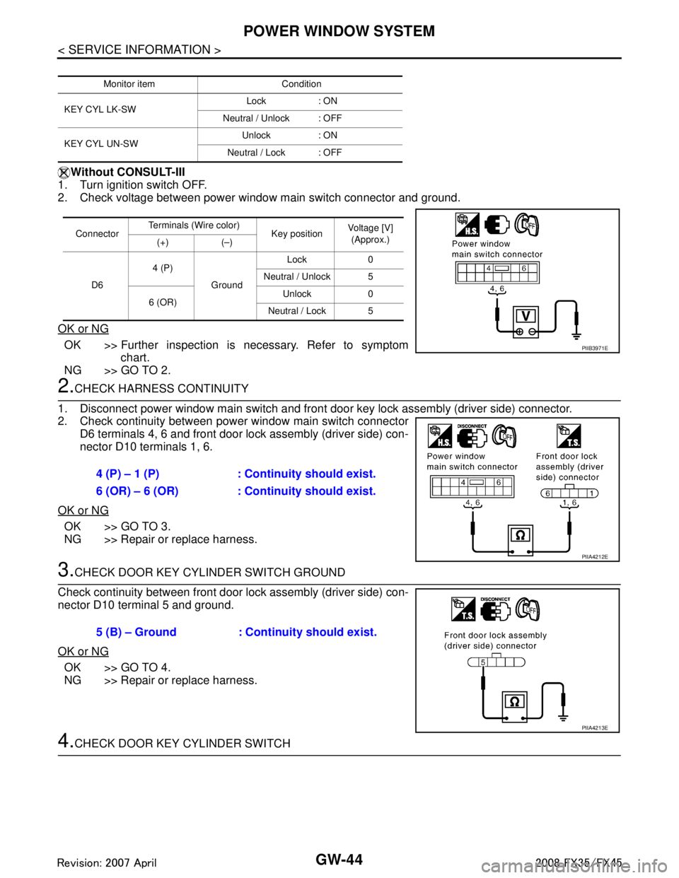
Without CONSULT-III
1. Turn ignition switch OFF.
2. Check voltage between power window main switch connector and ground.
OK or NG
OK >> Further inspection is necessary. Refer to symptom chart.
NG >> GO TO 2.
2.CHECK HARNESS CONTINUITY
1. Disconnect power window main switch and front door key lock assembly (driver side) connector.
2. Check continuity between power window main switch connector D6 terminals 4, 6 and front door lock assembly (driver side) con-
nector D10 terminals 1, 6.
OK or NG
OK >> GO TO 3.
NG >> Repair or replace harness.
3.CHECK DOOR KEY CYLINDER SWITCH GROUND
Check continuity between front door lock assembly (driver side) con-
nector D10 terminal 5 and ground.
OK or NG
OK >> GO TO 4.
NG >> Repair or replace harness.
4.CHECK DOOR KEY CYLINDER SWITCH
Monitor item Condition
KEY CYL LK-SW Lock : ON
Neutral / Unlock : OFF
KEY CYL UN-SW Unlock : ON
Neutral / Lock : OFF
Connector Terminals (Wire color)
Key position Voltage [V]
(Approx.)
(+) (–)
D6 4 (P)
Ground Lock 0
Neutral / Unlock 5
6 (OR) Unlock 0
Neutral / Lock 5
PIIB3971E
4 (P) – 1 (P) : Conti nuity should exist.
6 (OR) – 6 (OR) : Cont inuity should exist.
PIIA4212E
5 (B) – Ground : Continuity should exist.
PIIA4213E
3AA93ABC3ACD3AC03ACA3AC03AC63AC53A913A773A893A873A873A8E3A773A983AC73AC93AC03AC3
3A893A873A873A8F3A773A9D3AAF3A8A3A8C3A863A9D3AAF3A8B3A8C