2008 INFINITI FX35 ignition
[x] Cancel search: ignitionPage 2958 of 3924
POWER WINDOW SYSTEMGW-45
< SERVICE INFORMATION >
C
DE
F
G H
J
K L
M A
B
GW
N
O P
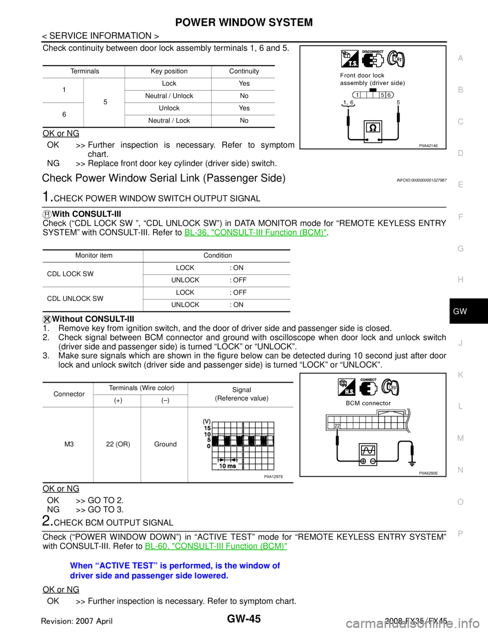
Check continuity between door lock assembly terminals 1, 6 and 5.
OK or NG
OK >> Further inspection is necessary. Refer to symptom chart.
NG >> Replace front door key cylinder (driver side) switch.
Check Power Window Serial Link (Passenger Side)INFOID:0000000001327987
1.CHECK POWER WINDOW SWITCH OUTPUT SIGNAL
With CONSULT-III
Check (“CDL LOCK SW ”, “CDL UNLOCK SW”) in DATA MONITOR mode for “REMOTE KEYLESS ENTRY
SYSTEM” with CONSULT-III. Refer to BL-36, "
CONSULT-III Function (BCM)".
Without CONSULT-III
1. Remove key from ignition switch, and the door of driver side and passenger side is closed.
2. Check signal between BCM connector and ground wit h oscilloscope when door lock and unlock switch
(driver side and passenger side) is turned “LOCK” or “UNLOCK”.
3. Make sure signals which are shown in the figure below can be detected during 10 second just after door
lock and unlock switch (driver side and passenger side) is turned “LOCK” or “UNLOCK”.
OK or NG
OK >> GO TO 2.
NG >> GO TO 3.
2.CHECK BCM OUTPUT SIGNAL
Check (“POWER WINDOW DOWN”) in “ACTIVE T EST” mode for “REMOTE KEYLESS ENTRY SYSTEM”
with CONSULT-III. Refer to BL-60, "
CONSULT-III Function (BCM)"
OK or NG
OK >> Further inspection is necessary. Refer to symptom chart.
Terminals Key position Continuity
1 5 Lock Yes
Neutral / Unlock No
6 Unlock Yes
Neutral / Lock No
PIIA4214E
Monitor item Condition
CDL LOCK SW LOCK : ON
UNLOCK : OFF
CDL UNLOCK SW LOCK : OFF
UNLOCK : ON
Connector Terminals (W
ire color)
Signal
(Reference value)
(+) (–)
M3 22 (OR) Ground
PIIA6290EPIIA1297E
When “ACTIVE TEST” is performed, is the window of
driver side and passenger side lowered.
3AA93ABC3ACD3AC03ACA3AC03AC63AC53A913A773A893A873A873A8E3A773A983AC73AC93AC03AC3
3A893A873A873A8F3A773A9D3AAF3A8A3A8C3A863A9D3AAF3A8B3A8C
Page 2959 of 3924
GW-46
< SERVICE INFORMATION >
POWER WINDOW SYSTEM
NG >> Replace BCM.
3.CHECK POWER WINDOW SWITCH GROUND
1. Turn ignition switch OFF.
2. Disconnect power window main switch and front power window switch (passenger side) connector.
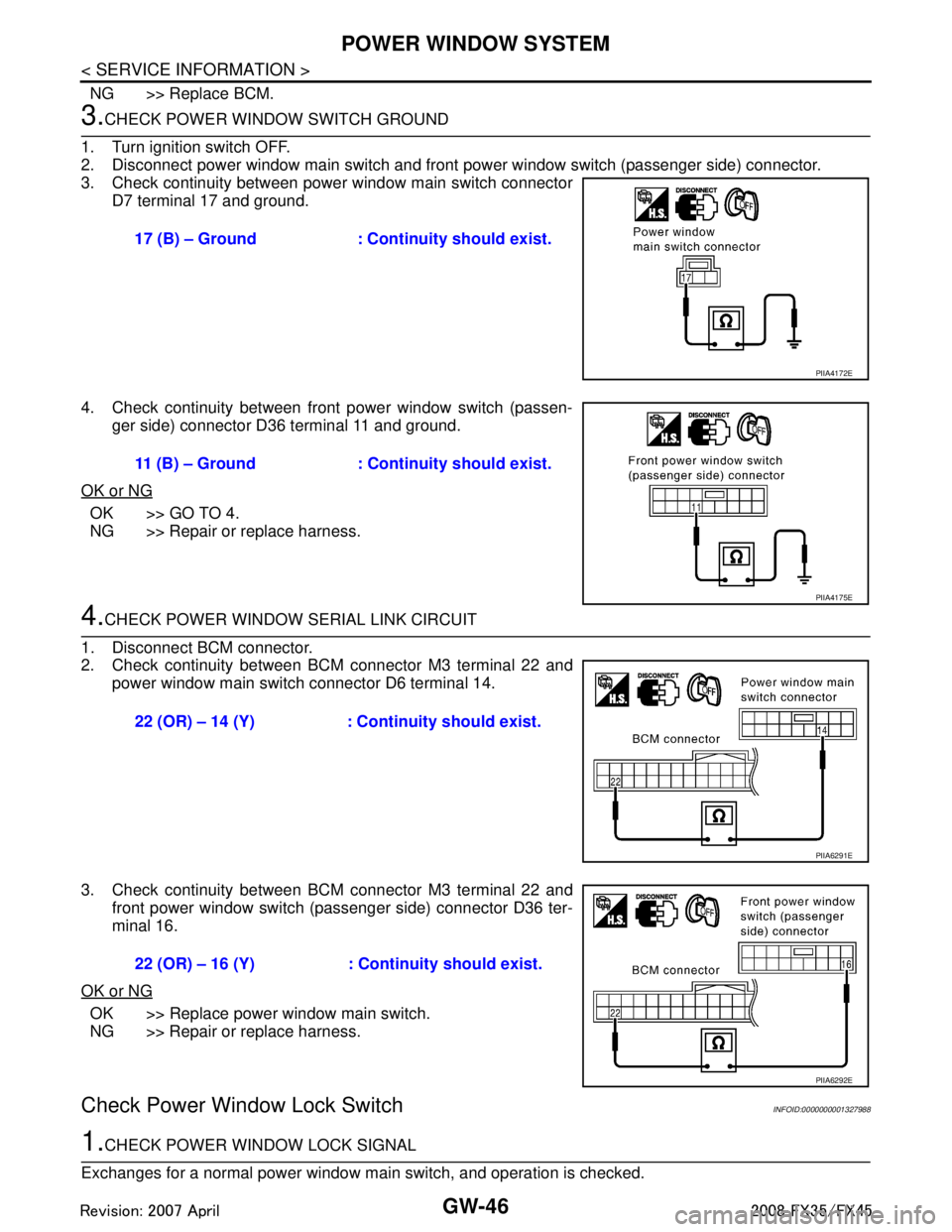
3. Check continuity between power window main switch connector D7 terminal 17 and ground.
4. Check continuity between front power window switch (passen- ger side) connector D36 terminal 11 and ground.
OK or NG
OK >> GO TO 4.
NG >> Repair or replace harness.
4.CHECK POWER WINDOW SERIAL LINK CIRCUIT
1. Disconnect BCM connector.
2. Check continuity between BCM connector M3 terminal 22 and power window main switch connector D6 terminal 14.
3. Check continuity between BCM connector M3 terminal 22 and front power window switch (passenger side) connector D36 ter-
minal 16.
OK or NG
OK >> Replace power window main switch.
NG >> Repair or replace harness.
Check Power Window Lock SwitchINFOID:0000000001327988
1.CHECK POWER WINDOW LOCK SIGNAL
Exchanges for a normal power window main switch, and operation is checked. 17 (B) – Ground : Continuity should exist.
PIIA4172E
11 (B) – Ground : Continuity should exist.
PIIA4175E
22 (OR) – 14 (Y) : Cont
inuity should exist.
PIIA6291E
22 (OR) – 16 (Y) : Cont inuity should exist.
PIIA6292E
3AA93ABC3ACD3AC03ACA3AC03AC63AC53A913A773A893A873A873A8E3A773A983AC73AC93AC03AC3
3A893A873A873A8F3A773A9D3AAF3A8A3A8C3A863A9D3AAF3A8B3A8C
Page 2973 of 3924
GW-60
< SERVICE INFORMATION >
REAR WINDOW DEFOGGER
REAR WINDOW DEFOGGER
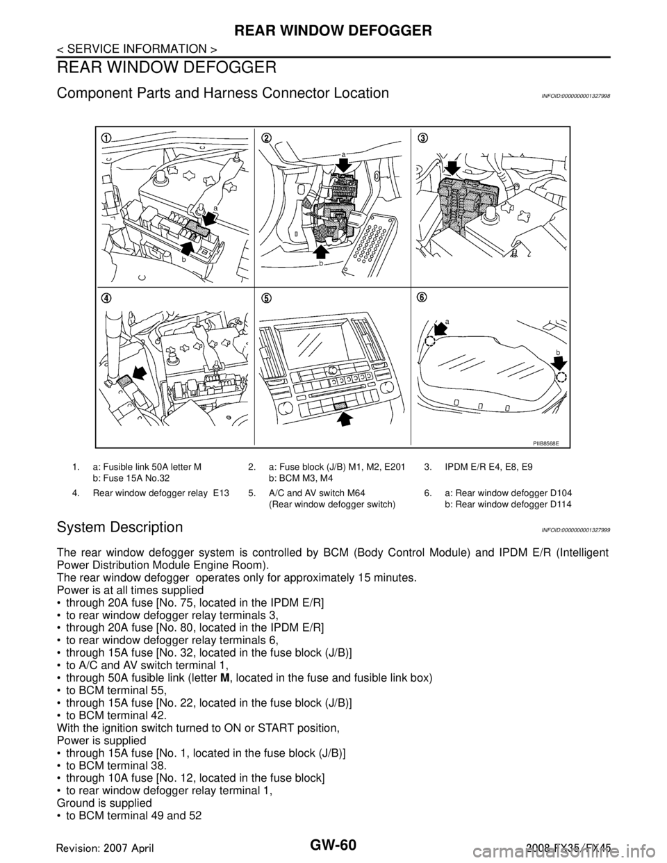
Component Parts and Harness Connector LocationINFOID:0000000001327998
System DescriptionINFOID:0000000001327999
The rear window defogger system is controlled by BC M (Body Control Module) and IPDM E/R (Intelligent
Power Distribution Module Engine Room).
The rear window defogger operates only for approximately 15 minutes.
Power is at all times supplied
through 20A fuse [No. 75, located in the IPDM E/R]
to rear window defogger relay terminals 3,
through 20A fuse [No. 80, located in the IPDM E/R]
to rear window defogger relay terminals 6,
through 15A fuse [No. 32, located in the fuse block (J/B)]
to A/C and AV switch terminal 1,
through 50A fusible link (letter M, located in the fuse and fusible link box)
to BCM terminal 55,
through 15A fuse [No. 22, located in the fuse block (J/B)]
to BCM terminal 42.
With the ignition switch turned to ON or START position,
Power is supplied
through 15A fuse [No. 1, located in the fuse block (J/B)]
to BCM terminal 38.
through 10A fuse [No. 12, located in the fuse block]
to rear window defogger relay terminal 1,
Ground is supplied
to BCM terminal 49 and 52
1. a: Fusible link 50A letter M
b: Fuse 15A No.32 2. a: Fuse block (J/B) M1, M2, E201
b: BCM M3, M4 3. IPDM E/R E4, E8, E9
4. Rear window defogger relay E13 5. A/C and AV switch M64 (Rear window defogger switch)6. a: Rear window defogger D104
b: Rear window defogger D114
PIIB8568E
3AA93ABC3ACD3AC03ACA3AC03AC63AC53A913A773A893A873A873A8E3A773A983AC73AC93AC03AC3
3A893A873A873A8F3A773A9D3AAF3A8A3A8C3A863A9D3AAF3A8B3A8C
Page 2980 of 3924

REAR WINDOW DEFOGGERGW-67
< SERVICE INFORMATION >
C
DE
F
G H
J
K L
M A
B
GW
N
O P
Terminal and Reference Value for BCMINFOID:0000000001328004
Terminal and Reference Value for IPDM E/RINFOID:0000000001328005
CONSULT-III Function (BCM)INFOID:0000000001328006
DATA MONITOR
ACTIVE TEST
Te r m i n a l Wire col-
or ItemSignal In-
put/
Output Condition
Voltage (V)
(Approx.)
9L/W Rear window defogger
switch signal InputWhen rear window defogger switch is
pressed.
0
When rear window defogger switch is OFF. 5
38 W/L Ignition switch ON or START Input Ignition switch (ON or START position) Battery voltage
39 L CAN − H Input/
Output ——
40 P CAN − L Input/
Output ——
42 L/R Power source (Fuse) Input — Battery voltage
49 B Ground (signal) — — 0
52 B Ground (power) — — 0
55 G Power source (Fusible link) Input — Battery voltage
Te r m i n a l Wire col-
or Item Signal
Input/
Output Condition
Voltage (V)
(Approx.)
5 R Battery power supply Output — Battery voltage
6 W Battery power supply Output — Battery voltage
38 B Ground (Power) — — 0
48 L CAN − H Input/
Output ——
49 R CAN − L Input/
Output ——
52 G Rear window defogger relay
control signal
InputWhen rear window defogger switch is ON. 0
When rear window defogger switch is
OFF.
Battery voltage
60 B Ground (Signal) — — 0
BCM diagnostic test item Check item diagnostic test mode Content
REAR DEFOGGER Data monitor Displays the input data of BCM in real time.
Active test Gives a drive signal to a load to check the operation.
Monitor item Content
REAR DEF SW Displays “Press (ON)/others (OFF)” status determined with the rear window defogger switch.
IGN ON SW Displays “IGN (ON)/OFF” status determined with the ignition switch signal.
3AA93ABC3ACD3AC03ACA3AC03AC63AC53A913A773A893A873A873A8E3A773A983AC73AC93AC03AC3
3A893A873A873A8F3A773A9D3AAF3A8A3A8C3A863A9D3AAF3A8B3A8C
Page 2982 of 3924
REAR WINDOW DEFOGGERGW-69
< SERVICE INFORMATION >
C
DE
F
G H
J
K L
M A
B
GW
N
O P
Check BCM Power Supply and Ground CircuitINFOID:0000000001328010
First perform the “SELF-DIAG RESULTS” in “BCM” with CONSULT-III, when perform the each trouble
diagnosis. Refer to BCS-13, "
U1000 CAN Communication Circuit".
1.CHECK FUSE
Check 15A fuse [No.1, located in the fuse block (J/B)]
Check 15A fuse [No.22, located in the fuse block (J/B)]
Check 50A fusible link (letter M located in the fuse and fusible link box).
NOTE:
Refer to GW-60, "
Component Parts and Harness Connector Location".
OK or NG
OK >> GO TO 2.
NG >> If fuse is blown out, be sure to eliminate c ause of malfunction before installing new fuse. Refer to
PG-3
.
2.CHECK POWER SUPPLY CIRCUIT
1. Turn ignition switch ON.
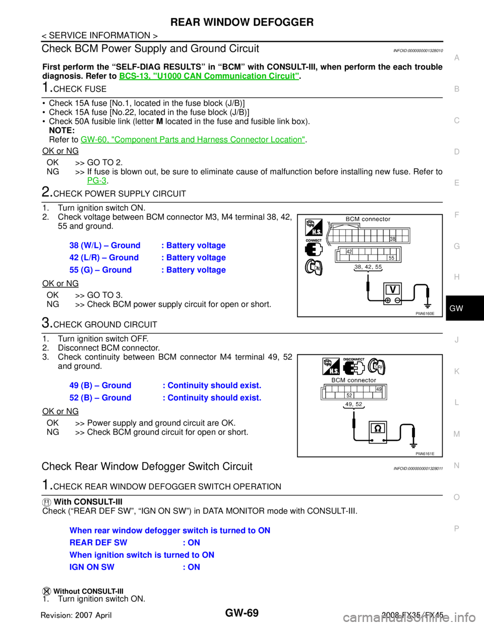
2. Check voltage between BCM connector M3, M4 terminal 38, 42, 55 and ground.
OK or NG
OK >> GO TO 3.
NG >> Check BCM power supply circuit for open or short.
3.CHECK GROUND CIRCUIT
1. Turn ignition switch OFF.
2. Disconnect BCM connector.
3. Check continuity between BCM connector M4 terminal 49, 52 and ground.
OK or NG
OK >> Power supply and ground circuit are OK.
NG >> Check BCM ground circuit for open or short.
Check Rear Window Defogger Switch CircuitINFOID:0000000001328011
1.CHECK REAR WINDOW DEF OGGER SWITCH OPERATION
With CONSULT-III
Check (“REAR DEF SW”, “IGN ON SW”) in DATA MONITOR mode with CONSULT-III.
Without CONSULT-III1. Turn ignition switch ON. 38 (W/L) – Ground : Battery voltage
42 (L/R) – Ground : Battery voltage
55 (G) – Ground : Battery voltage
PIIA6160E
49 (B) – Ground : Continuity should exist.
52 (B) – Ground : Continuity should exist.
PIIA6161E
When rear window defogger switch is turned to ON
REAR DEF SW : ON
When ignition switch is turned to ON
IGN ON SW : ON
3AA93ABC3ACD3AC03ACA3AC03AC63AC53A913A773A893A873A873A8E3A773A983AC73AC93AC03AC3
3A893A873A873A8F3A773A9D3AAF3A8A3A8C3A863A9D3AAF3A8B3A8C
Page 2983 of 3924
GW-70
< SERVICE INFORMATION >
REAR WINDOW DEFOGGER
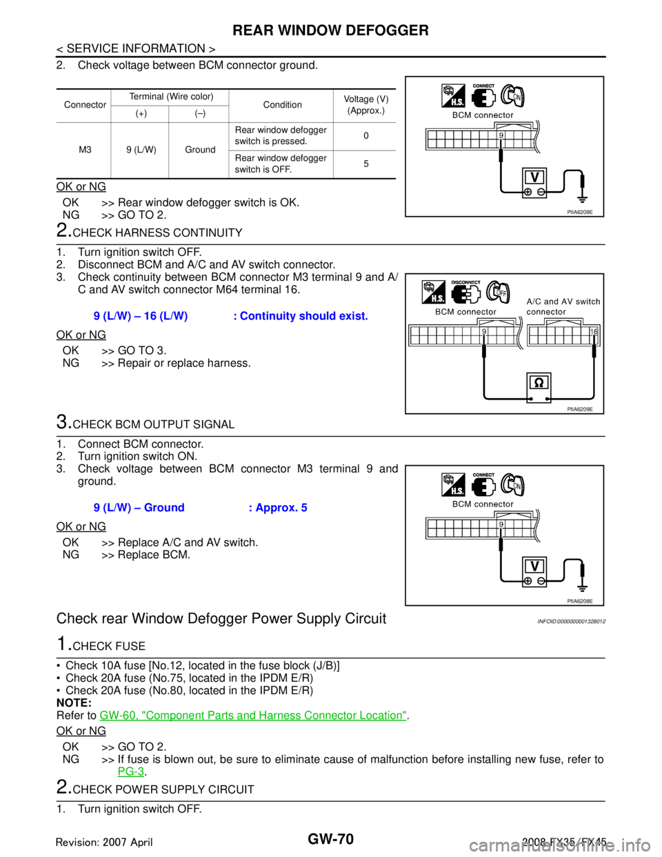
2. Check voltage between BCM connector ground.
OK or NG
OK >> Rear window defogger switch is OK.
NG >> GO TO 2.
2.CHECK HARNESS CONTINUITY
1. Turn ignition switch OFF.
2. Disconnect BCM and A/C and AV switch connector.
3. Check continuity between BCM connector M3 terminal 9 and A/ C and AV switch connector M64 terminal 16.
OK or NG
OK >> GO TO 3.
NG >> Repair or replace harness.
3.CHECK BCM OUTPUT SIGNAL
1. Connect BCM connector.
2. Turn ignition switch ON.
3. Check voltage between BCM connector M3 terminal 9 and ground.
OK or NG
OK >> Replace A/C and AV switch.
NG >> Replace BCM.
Check rear Window Defogger Power Supply CircuitINFOID:0000000001328012
1.CHECK FUSE
Check 10A fuse [No.12, located in the fuse block (J/B)]
Check 20A fuse (No.75, located in the IPDM E/R)
Check 20A fuse (No.80, located in the IPDM E/R)
NOTE:
Refer to GW-60, "
Component Parts and Harness Connector Location".
OK or NG
OK >> GO TO 2.
NG >> If fuse is blown out, be sure to eliminate cause of malfunction before installing new fuse, refer to PG-3
.
2.CHECK POWER SUPPLY CIRCUIT
1. Turn ignition switch OFF.
Connector Terminal (Wire color)
ConditionVoltage (V)
(Approx.)
(+) (–)
M3 9 (L/W) Ground Rear window defogger
switch is pressed.
0
Rear window defogger
switch is OFF. 5
PIIA6208E
9 (L/W) – 16 (L/W) : Cont
inuity should exist.
PIIA6209E
9 (L/W) – Ground : Approx. 5
PIIA6208E
3AA93ABC3ACD3AC03ACA3AC03AC63AC53A913A773A893A873A873A8E3A773A983AC73AC93AC03AC3
3A893A873A873A8F3A773A9D3AAF3A8A3A8C3A863A9D3AAF3A8B3A8C
Page 2984 of 3924
REAR WINDOW DEFOGGERGW-71
< SERVICE INFORMATION >
C
DE
F
G H
J
K L
M A
B
GW
N
O P
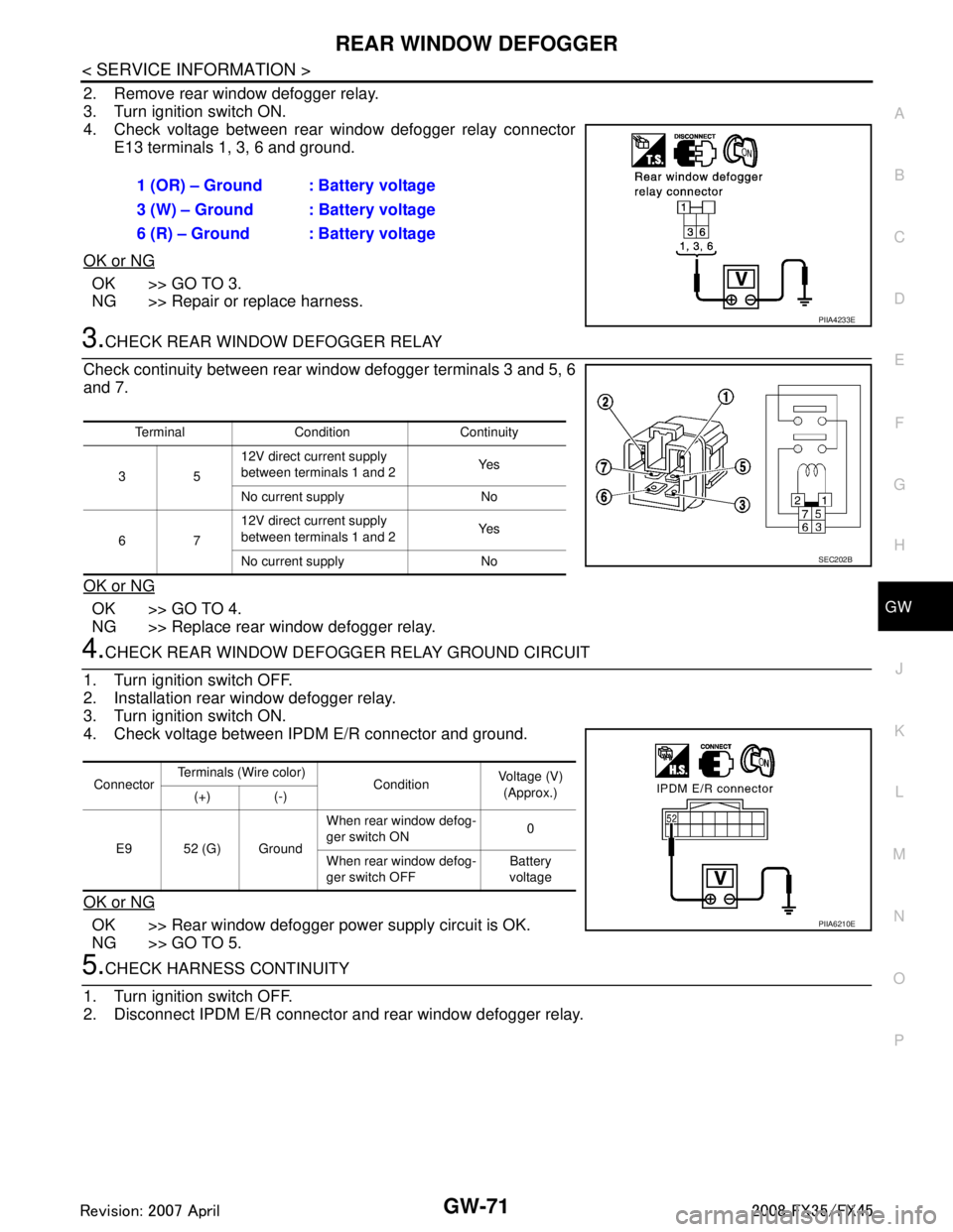
2. Remove rear window defogger relay.
3. Turn ignition switch ON.
4. Check voltage between rear window defogger relay connector E13 terminals 1, 3, 6 and ground.
OK or NG
OK >> GO TO 3.
NG >> Repair or replace harness.
3.CHECK REAR WINDOW DEFOGGER RELAY
Check continuity between rear wi ndow defogger terminals 3 and 5, 6
and 7.
OK or NG
OK >> GO TO 4.
NG >> Replace rear window defogger relay.
4.CHECK REAR WINDOW DEFOGG ER RELAY GROUND CIRCUIT
1. Turn ignition switch OFF.
2. Installation rear window defogger relay.
3. Turn ignition switch ON.
4. Check voltage between IPDM E/R connector and ground.
OK or NG
OK >> Rear window defogger power supply circuit is OK.
NG >> GO TO 5.
5.CHECK HARNESS CONTINUITY
1. Turn ignition switch OFF.
2. Disconnect IPDM E/R connector and rear window defogger relay. 1 (OR) – Ground : Battery voltage
3 (W) – Ground : Battery voltage
6 (R) – Ground : Battery voltage
PIIA4233E
Terminal Condition Continuity
35 12V direct current supply
between terminals 1 and 2
Ye s
No current supply No
67 12V direct current supply
between terminals 1 and 2
Ye s
No current supply No
SEC202B
Connector Terminals (Wire color)
ConditionVoltage (V)
(Approx.)
(+) (-)
E9 52 (G) Ground When rear window defog-
ger switch ON
0
When rear window defog-
ger switch OFF Battery
voltage
PIIA6210E
3AA93ABC3ACD3AC03ACA3AC03AC63AC53A913A773A893A873A873A8E3A773A983AC73AC93AC03AC3
3A893A873A873A8F3A773A9D3AAF3A8A3A8C3A863A9D3AAF3A8B3A8C
Page 2985 of 3924

GW-72
< SERVICE INFORMATION >
REAR WINDOW DEFOGGER
3. Check continuity between IPDM E/R connector E9 terminal 52and rear window defogger relay connector E13 terminal 2.
OK or NG
OK >> GO TO 6.
NG >> Repair or replace harness.
6.CHECK REAR WINDOW DEFOGGER RELAY OUTPUT SIGNAL
1. Connect IPDM E/R connector and rear window defogger relay.
2. Turn ignition switch ON.
3. Check voltage between IPDM E/R connector E9 terminal 52 and ground.
OK or NG
OK >> Check condition of harness and connector.
NG >> Replace IPDM E/R.
Check Rear Window Defogger CircuitINFOID:0000000001328013
1.CHECK POWER SUPPLY CIRCUIT 1
1. Turn ignition switch OFF.
2. Disconnect rear window defogger connector.
3. Turn ignition switch ON.
4. Check voltage between rear window defogger connector and ground.
OK or NG
OK >> GO TO 2.
NG >> GO TO 3.
2.CHECK GROUND CIRCUIT
1. Turn ignition switch OFF. 52 (G) – 2 (G) : Continuity should exist.
PIIA6211E
52 (G) – Ground : Battery voltage
PIIA6210E
Connector
Terminal (Wire color)
ConditionVoltage (V)
(Approx.)
(+) (–)
D104 1(W) Ground Rear window defogger
switch ON.
Battery voltage
Rear window defogger
switch OFF. 0
PIIA9347E
3AA93ABC3ACD3AC03ACA3AC03AC63AC53A913A773A893A873A873A8E3A773A983AC73AC93AC03AC3
3A893A873A873A8F3A773A9D3AAF3A8A3A8C3A863A9D3AAF3A8B3A8C