2008 INFINITI FX35 ignition
[x] Cancel search: ignitionPage 2986 of 3924

REAR WINDOW DEFOGGERGW-73
< SERVICE INFORMATION >
C
DE
F
G H
J
K L
M A
B
GW
N
O P
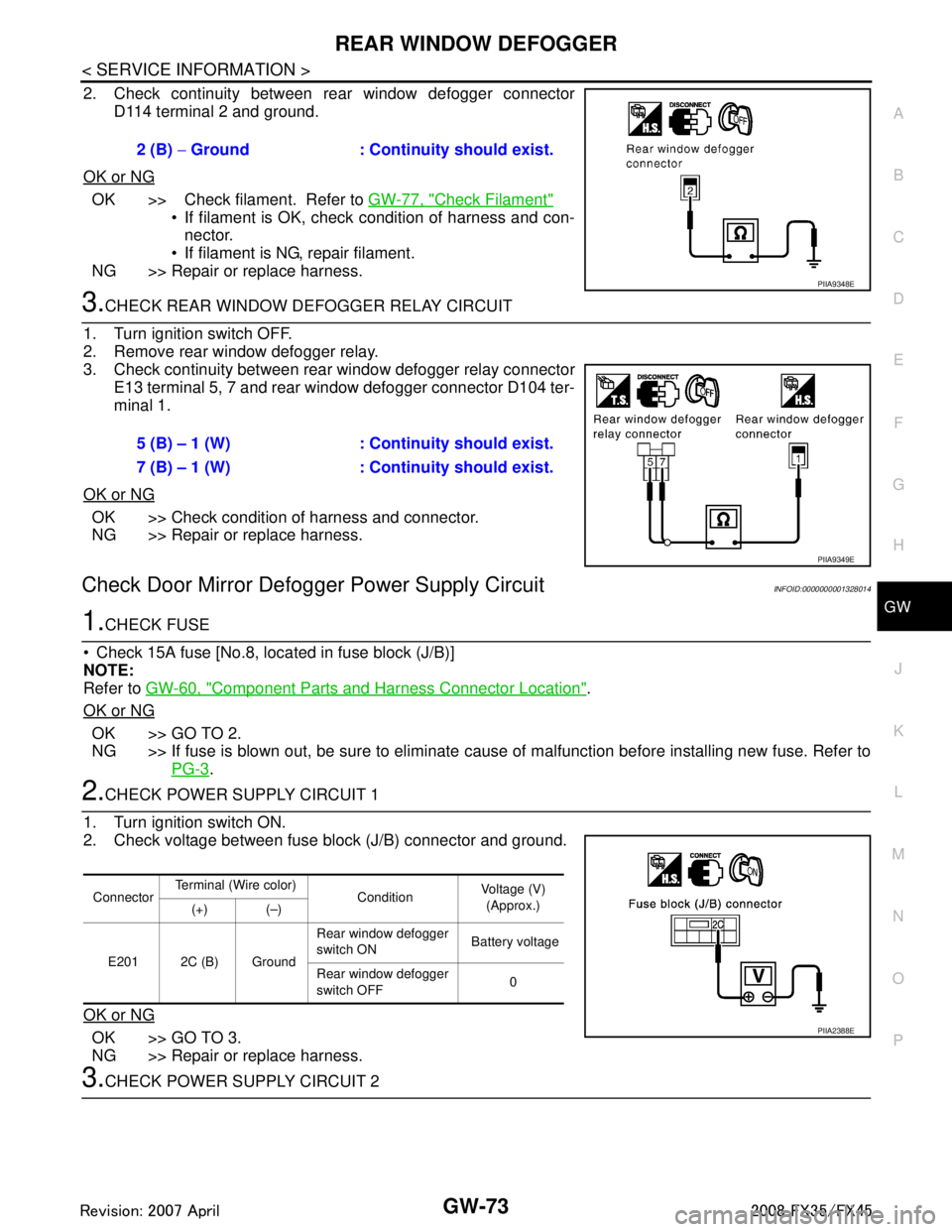
2. Check continuity between rear window defogger connector D114 terminal 2 and ground.
OK or NG
OK >> Check filament. Refer to GW-77, "Check Filament"
If filament is OK, check condition of harness and con-
nector.
If filament is NG, repair filament.
NG >> Repair or replace harness.
3.CHECK REAR WINDOW DEFOGGER RELAY CIRCUIT
1. Turn ignition switch OFF.
2. Remove rear window defogger relay.
3. Check continuity between rear window defogger relay connector E13 terminal 5, 7 and rear window defogger connector D104 ter-
minal 1.
OK or NG
OK >> Check condition of harness and connector.
NG >> Repair or replace harness.
Check Door Mirror Defogger Power Supply CircuitINFOID:0000000001328014
1.CHECK FUSE
Check 15A fuse [No.8, loca ted in fuse block (J/B)]
NOTE:
Refer to GW-60, "
Component Parts and Harness Connector Location".
OK or NG
OK >> GO TO 2.
NG >> If fuse is blown out, be sure to eliminate c ause of malfunction before installing new fuse. Refer to
PG-3
.
2.CHECK POWER SUPPLY CIRCUIT 1
1. Turn ignition switch ON.
2. Check voltage between fuse block (J/B) connector and ground.
OK or NG
OK >> GO TO 3.
NG >> Repair or replace harness.
3.CHECK POWER SUPPLY CIRCUIT 2 2 (B)
− Ground : Continuity should exist.
PIIA9348E
5 (B) – 1 (W) : Cont inuity should exist.
7 (B) – 1 (W) : Cont inuity should exist.
PIIA9349E
ConnectorTerminal (Wire color)
ConditionVoltage (V)
(Approx.)
(+) (–)
E201 2C (B) Ground Rear window defogger
switch ON
Battery voltage
Rear window defogger
switch OFF 0
PIIA2388E
3AA93ABC3ACD3AC03ACA3AC03AC63AC53A913A773A893A873A873A8E3A773A983AC73AC93AC03AC3
3A893A873A873A8F3A773A9D3AAF3A8A3A8C3A863A9D3AAF3A8B3A8C
Page 2987 of 3924

GW-74
< SERVICE INFORMATION >
REAR WINDOW DEFOGGER
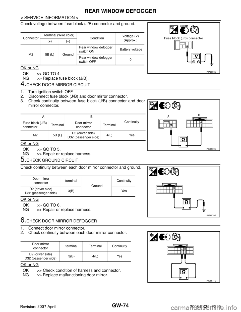
Check voltage between fuse block (J/B) connector and ground.
OK or NG
OK >> GO TO 4.
NG >> Replace fuse block (J/B).
4.CHECK DOOR MIRROR CIRCUIT
1. Turn ignition switch OFF.
2. Disconnect fuse block (J/B) and door mirror connector.
3. Check continuity between fuse block (J/B) connector and door mirror connector.
OK or NG
OK >> GO TO 5.
NG >> Repair or replace harness.
5.CHECK GROUND CIRCUIT
Check continuity between each door mirror connector and ground.
OK or NG
OK >> GO TO 6.
NG >> Repair or replace harness.
6.CHECK DOOR MIRROR DEFOGGER
1. Connect door mirror connector.
2. Check continuity between each door mirror connector.
OK or NG
OK >> Check condition of harness and connector.
NG >> Replace malfunctioning door mirror.
Connector Terminal (Wire color)
ConditionVoltage (V)
(Approx.)
(+) (–)
M2 5B (L) Ground Rear window defogger
switch ON
Battery voltage
Rear window defogger
switch OFF 0
PIIA2386E
AB
Continuity
Fuse block (J/B)
connector Te r m i n a lDoor mirror
connector Te r m i n a l
M2 5B (L) D2 (driver side)
D32 (passenger side) 4(L) Yes
PIIB8569E
Door mirror
connector terminal
GroundContinuity
D2 (driver side)
D32 (passenger side) 3(B) Yes
PIIB8570E
Door mirror
connector terminal Terminal Continuity
D2 (driver side)
D32 (passenger side) 3(B) 4(L) Yes
PIIB8571E
3AA93ABC3ACD3AC03ACA3AC03AC63AC53A913A773A893A873A873A8E3A773A983AC73AC93AC03AC3
3A893A873A873A8F3A773A9D3AAF3A8A3A8C3A863A9D3AAF3A8B3A8C
Page 2988 of 3924

REAR WINDOW DEFOGGERGW-75
< SERVICE INFORMATION >
C
DE
F
G H
J
K L
M A
B
GW
N
O P
Check Driver Side Door Mirror Defogger CircuitINFOID:0000000001328015
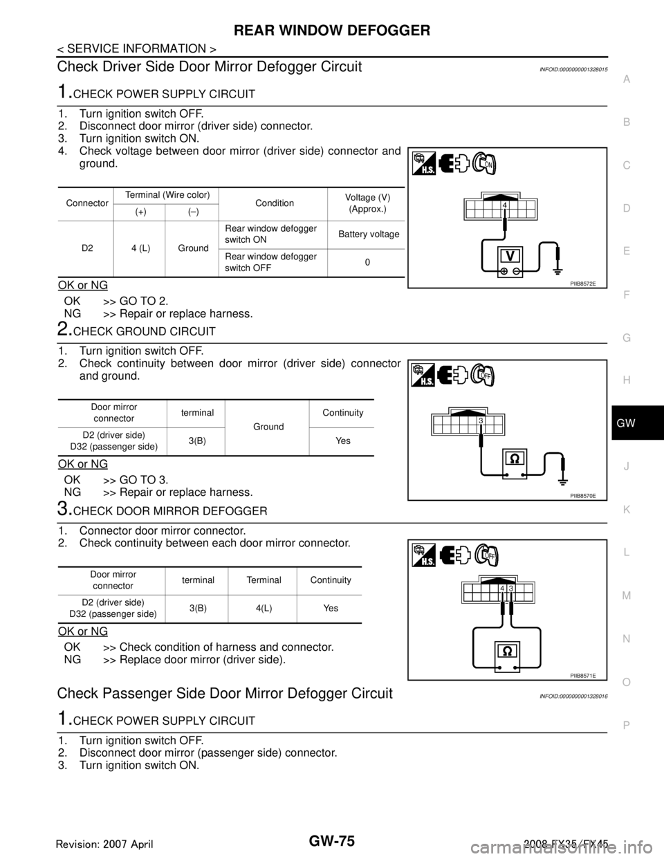
1.CHECK POWER SUPPLY CIRCUIT
1. Turn ignition switch OFF.
2. Disconnect door mirror (driver side) connector.
3. Turn ignition switch ON.
4. Check voltage between door mirror (driver side) connector and ground.
OK or NG
OK >> GO TO 2.
NG >> Repair or replace harness.
2.CHECK GROUND CIRCUIT
1. Turn ignition switch OFF.
2. Check continuity between door mirror (driver side) connector and ground.
OK or NG
OK >> GO TO 3.
NG >> Repair or replace harness.
3.CHECK DOOR MIRROR DEFOGGER
1. Connector door mirror connector.
2. Check continuity between each door mirror connector.
OK or NG
OK >> Check condition of harness and connector.
NG >> Replace door mirror (driver side).
Check Passenger Si de Door Mirror Defogger CircuitINFOID:0000000001328016
1.CHECK POWER SUPPLY CIRCUIT
1. Turn ignition switch OFF.
2. Disconnect door mirror (passenger side) connector.
3. Turn ignition switch ON.
Connector Terminal (Wire color)
ConditionVoltage (V)
(Approx.)
(+) (–)
D2 4 (L) Ground Rear window defogger
switch ON
Battery voltage
Rear window defogger
switch OFF 0
PIIB8572E
Door mirror
connector terminal
GroundContinuity
D2 (driver side)
D32 (passenger side) 3(B) Yes
PIIB8570E
Door mirror
connector terminal Terminal Continuity
D2 (driver side)
D32 (passenger side) 3(B) 4(L) Yes
PIIB8571E
3AA93ABC3ACD3AC03ACA3AC03AC63AC53A913A773A893A873A873A8E3A773A983AC73AC93AC03AC3
3A893A873A873A8F3A773A9D3AAF3A8A3A8C3A863A9D3AAF3A8B3A8C
Page 2989 of 3924

GW-76
< SERVICE INFORMATION >
REAR WINDOW DEFOGGER
4. Check voltage between door mirror (passenger side) connectorand ground.
OK or NG
OK >> GO TO 2.
NG >> Repair or replace harness.
2.CHECK GROUND CIRCUIT
1. Turn ignition switch OFF.
2. Check continuity between door mirror (passenger side) connec- tor and ground.
OK or NG
OK >> GO TO 3.
NG >> Repair or replace harness.
3.CHECK DOOR MIRROR DEFOGGER
1. Connector door mirror connector.
2. Check continuity between each door mirror connector.
OK or NG
OK >> Check condition of harness and connector.
NG >> Replace door mirror (passenger side).
Check Rear Windo w Defogger SignalINFOID:0000000001328017
1.CHECK REAR WINDOW DEFOGGER SWITCH LAMP
A/C and AV switch self-diagnosis is performed. Refer to AV-34, "
A/C and AV Switch Self-Diagnosis Function"
Does rear window defogger switch light?
YES >> GO TO 2.
NO >> Replace A/C and AV switch.
2.CHECK AV COMMUNICATION LINE
AV communication line check is performed. Refer to AV-79, "
Unable to Operate System with A/C and AV
Switch"
Is rear window defogger displayed on the display?
YES >> GO TO 3.
NO >> Replace display control unit.
3.CHECK CAN COMMUNICATION LINE
ConnectorTerminal (Wire color)
ConditionVoltage (V)
(Approx.)
(+) (–)
D32 4 (L) Ground Rear window defogger
switch ON
Battery voltage
Rear window defogger
switch OFF 0
PIIB8572E
Door mirror
connector terminal
GroundContinuity
D2 (driver side)
D32 (passenger side) 3(B) Yes
PIIB8570E
Door mirror
connector terminal Terminal Continuity
D2 (driver side)
D32 (passenger side) 3(B) 4(L) Yes
PIIB8571E
3AA93ABC3ACD3AC03ACA3AC03AC63AC53A913A773A893A873A873A8E3A773A983AC73AC93AC03AC3
3A893A873A873A8F3A773A9D3AAF3A8A3A8C3A863A9D3AAF3A8B3A8C
Page 3023 of 3924
![INFINITI FX35 2008 Service Manual
PRECAUTIONSLAN-3
< SERVICE INFORMATION > [CAN FUNDAMENTAL]
C
D
E
F
G H
I
J
L
M A
B
LAN
N
O P
SERVICE INFORMATION
PRECAUTIONS
Precaution for Trouble DiagnosisINFOID:0000000001451944
CAUTION:
• Never INFINITI FX35 2008 Service Manual
PRECAUTIONSLAN-3
< SERVICE INFORMATION > [CAN FUNDAMENTAL]
C
D
E
F
G H
I
J
L
M A
B
LAN
N
O P
SERVICE INFORMATION
PRECAUTIONS
Precaution for Trouble DiagnosisINFOID:0000000001451944
CAUTION:
• Never](/manual-img/42/57017/w960_57017-3022.png)
PRECAUTIONSLAN-3
< SERVICE INFORMATION > [CAN FUNDAMENTAL]
C
D
E
F
G H
I
J
L
M A
B
LAN
N
O P
SERVICE INFORMATION
PRECAUTIONS
Precaution for Trouble DiagnosisINFOID:0000000001451944
CAUTION:
• Never apply 7.0 V or more to the measurement terminal.
Use a tester with open terminal voltage of 7.0 V or less.
Turn the ignition switch OFF and disconnect th e battery cable from the negative terminal when
checking the harness.
Precaution for Harness RepairINFOID:0000000001451945
• Solder the repaired area and wrap tape around the soldered area. NOTE:
A fray of twisted lines must be within 110 mm (4.33 in).
Bypass connection is never allowed at the repaired area. NOTE:
Bypass connection may cause CAN communication error. The
spliced wire becomes separated and t he characteristics of twisted
line are lost.
Replace the applicable harness as an assembly if error is detected on the shield lines of CAN communica-
tion line.
SKIB8766E
SKIB8767E
3AA93ABC3ACD3AC03ACA3AC03AC63AC53A913A773A893A873A873A8E3A773A983AC73AC93AC03AC3
3A893A873A873A8F3A773A9D3AAF3A8A3A8C3A863A9D3AAF3A8B3A8C
Page 3027 of 3924
![INFINITI FX35 2008 Service Manual
TROUBLE DIAGNOSISLAN-7
< SERVICE INFORMATION > [CAN FUNDAMENTAL]
C
D
E
F
G H
I
J
L
M A
B
LAN
N
O P
TROUBLE DIAGNOSIS
Condition of Error DetectionINFOID:0000000001451948
“U1000” or “U1001” is INFINITI FX35 2008 Service Manual
TROUBLE DIAGNOSISLAN-7
< SERVICE INFORMATION > [CAN FUNDAMENTAL]
C
D
E
F
G H
I
J
L
M A
B
LAN
N
O P
TROUBLE DIAGNOSIS
Condition of Error DetectionINFOID:0000000001451948
“U1000” or “U1001” is](/manual-img/42/57017/w960_57017-3026.png)
TROUBLE DIAGNOSISLAN-7
< SERVICE INFORMATION > [CAN FUNDAMENTAL]
C
D
E
F
G H
I
J
L
M A
B
LAN
N
O P
TROUBLE DIAGNOSIS
Condition of Error DetectionINFOID:0000000001451948
“U1000” or “U1001” is indicated on SELF-DIAG RESULTS on CONSULT-III if CAN communication signal is
not transmitted or received between units for 2 seconds or more.
CAN COMMUNICATION SYSTEM ERROR
CAN communication line open (CAN-H, CAN-L, or both)
CAN communication line short (ground, betw een CAN communication lines, other harnesses)
Error of CAN communication control circuit of the unit connected to CAN communication line
WHEN “U1000” OR “U1001” IS INDICATED EV EN THOUGH CAN COMMUNICATION SYSTEM IS
NORMAL
Removal/installation of parts: Error may be detec ted when removing and installing CAN communication unit
and related parts while turning the ignition switch ON. (A DTC except for CAN communication may be
detected.)
Fuse blown out (removed): CAN communication of the unit may cease.
Voltage drop: Error may be detected if voltage drops due to discharged battery when turning the ignition
switch ON (Depending on the control unit which carries out CAN communication).
Error may be detected if the power supply circuit of the control unit, which carries out CAN communication,
malfunctions (Depending on the control unit which carries out CAN communication).
Error may be detected if reprogramming is not completed normally.
NOTE:
CAN communication system is normal if “U1000” or “U 1001” is indicated on SELF-DIAG RESULTS of CON-
SULT-III under the above conditions. Erase the memory of the self-diagnosis of each unit.
Symptom When Error Occurs in CAN Communication SystemINFOID:0000000001451949
In CAN communication system, multiple units mutually transmit and receive signals. Each unit cannot transmit
and receive signals if any error occurs on CAN communicati on line. Under this condition, multiple control units
related to the root cause malfunction or go into fail-safe mode.
ERROR EXAMPLE
NOTE:
Each vehicle differs in symptom of each unit under fail-safe mode and CAN communication line wiring.
Refer to LAN-37, "
Abbreviation List" for the unit abbreviation.
Example: TCM branch line open circuit
SKIB8738E
Unit name Symptom
ECM Engine torque limiting is affected, and shift harshness increases.
BCM Reverse warning chime does not sound.
3AA93ABC3ACD3AC03ACA3AC03AC63AC53A913A773A893A873A873A8E3A773A983AC73AC93AC03AC3
3A893A873A873A8F3A773A9D3AAF3A8A3A8C3A863A9D3AAF3A8B3A8C
Page 3029 of 3924
![INFINITI FX35 2008 Service Manual
TROUBLE DIAGNOSISLAN-9
< SERVICE INFORMATION > [CAN FUNDAMENTAL]
C
D
E
F
G H
I
J
L
M A
B
LAN
N
O P
Example: Main Line Between Data Link
Connector and ABS Actuator and Electr ic Unit (Control Unit) O INFINITI FX35 2008 Service Manual
TROUBLE DIAGNOSISLAN-9
< SERVICE INFORMATION > [CAN FUNDAMENTAL]
C
D
E
F
G H
I
J
L
M A
B
LAN
N
O P
Example: Main Line Between Data Link
Connector and ABS Actuator and Electr ic Unit (Control Unit) O](/manual-img/42/57017/w960_57017-3028.png)
TROUBLE DIAGNOSISLAN-9
< SERVICE INFORMATION > [CAN FUNDAMENTAL]
C
D
E
F
G H
I
J
L
M A
B
LAN
N
O P
Example: Main Line Between Data Link
Connector and ABS Actuator and Electr ic Unit (Control Unit) Open Circuit
Example: CAN-H, CAN-L Harness Short Circuit
SKIB8740E
Unit name Symptom
ECM Engine torque limiting is affected, and shift harshness increases.
BCM Reverse warning chime does not sound.
The front wiper moves under continuous operation mode even though the front wip-
er switch being in the intermittent position.
EPS control unit The steering effort increases.
Combination meter The shift position indicator and OD OFF indicator turn OFF.
The speedometer is inoperative.
The odo/trip meter stops.
ABS actuator and electric unit (control unit) Normal operation.
TCM No impact on operation.
IPDM E/R When the ignition switch is ON,
The headlamps (Lo) turn ON.
The cooling fan continues to rotate.
SKIB8741E
3AA93ABC3ACD3AC03ACA3AC03AC63AC53A913A773A893A873A873A8E3A773A983AC73AC93AC03AC3
3A893A873A873A8F3A773A9D3AAF3A8A3A8C3A863A9D3AAF3A8B3A8C
Page 3030 of 3924
![INFINITI FX35 2008 Service Manual
LAN-10
< SERVICE INFORMATION >[CAN FUNDAMENTAL]
TROUBLE DIAGNOSIS
Self-Diagnosis
INFOID:0000000001451950
CAN Diagnostic Support MonitorINFOID:0000000001451951
CONSULT-III and CAN diagnostic support m INFINITI FX35 2008 Service Manual
LAN-10
< SERVICE INFORMATION >[CAN FUNDAMENTAL]
TROUBLE DIAGNOSIS
Self-Diagnosis
INFOID:0000000001451950
CAN Diagnostic Support MonitorINFOID:0000000001451951
CONSULT-III and CAN diagnostic support m](/manual-img/42/57017/w960_57017-3029.png)
LAN-10
< SERVICE INFORMATION >[CAN FUNDAMENTAL]
TROUBLE DIAGNOSIS
Self-Diagnosis
INFOID:0000000001451950
CAN Diagnostic Support MonitorINFOID:0000000001451951
CONSULT-III and CAN diagnostic support monitor (on-boar d diagnosis function) are used for detecting root
cause.
MONITOR ITEM (CONSULT-III)
Unit name Symptom
ECM Engine torque limiting is affected, and shift harshness increases.
Engine speed drops.
BCM Reverse warning chime does not sound.
The front wiper moves under continuous operation mode even though the front
wiper switch being in the intermittent position.
The room lamp does not turn ON.
The engine does not start (if an error or malfunction occurs while turning the igni- tion switch OFF.)
The steering lock does not release (if an error or malfunction occurs while turning the ignition switch OFF.)
EPS control unit The steeri ng effort increases.
Combination meter The tachometer and the speedometer do not move.
Warning lamps turn ON.
Indicator lamps do not turn ON.
ABS actuator and electric unit (control unit) Normal operation.
TCM No impact on operation.
IPDM E/R When the ignition switch is ON,
The headlamps (Lo) turn ON.
The cooling fan continues to rotate.
DTC
Self-diagnosis item
(CONSULT-III indication) DTC detection condition Inspection/Action
U1000 CAN COMM CIRCUIT When ECM is not transmitting or receiving CAN
communication signal of OBD (emission-related
diagnosis) for 2 seconds or more.
Refer to LAN-13
.
When a control unit (except for ECM) is not
transmitting or receiving CAN communication
signal for 2 seconds or more.
U1001 CAN COMM CIRCUIT When ECM is not transmitting or receiving CAN
communication signal other than OBD (emis-
sion-related diagnosis) for 2 seconds or more.
U1002 SYSTEM COMM When a control unit is not transmitting or receiv-
ing CAN communication signal for 2 seconds or
less. Start the inspection. Re-
fer to the applicable sec-
tion of the indicated
control unit.
U1010 CONTROL UNIT [CAN] When an error is detected during the initial diag-
nosis for CAN controller of each control unit. Replace the control unit
indicating “U1010”.
3AA93ABC3ACD3AC03ACA3AC03AC63AC53A913A773A893A873A873A8E3A773A983AC73AC93AC03AC3
3A893A873A873A8F3A773A9D3AAF3A8A3A8C3A863A9D3AAF3A8B3A8C