2008 INFINITI FX35 ignition switch
[x] Cancel search: ignition switchPage 2678 of 3924
![INFINITI FX35 2008 Service Manual
EM-194
< SERVICE INFORMATION >[VK45DE]
FUEL INJECTOR AND FUEL TUBE
Tighten mounting bolts in two steps in numerical order as
shown in the figure.
6. Connect fuel feed hose on engine side as follows INFINITI FX35 2008 Service Manual
EM-194
< SERVICE INFORMATION >[VK45DE]
FUEL INJECTOR AND FUEL TUBE
Tighten mounting bolts in two steps in numerical order as
shown in the figure.
6. Connect fuel feed hose on engine side as follows](/manual-img/42/57017/w960_57017-2677.png)
EM-194
< SERVICE INFORMATION >[VK45DE]
FUEL INJECTOR AND FUEL TUBE
Tighten mounting bolts in two steps in numerical order as
shown in the figure.
6. Connect fuel feed hose on engine side as follows: (Unless otherwise indicated, the installation to the engine side and centralized under-floor piping side is exactly alike.)
a. Make sure no foreign substances are deposited in and around fuel tube and quick connector, and no dam- age on them.
b. Thinly apply new engine oil around fuel tube from tip end to spool end.
c. Align center to insert quick connector straightly into fuel tube. Engine side:
Insert fuel tube into quick connector until top spool is com-
pletely inside quick connector, and 2nd level spool exposes
right below quick connector.
CAUTION:
Hold “A” position as shown in the figure when inserting
fuel tube into quick connector.
Carefully align center to avoid inclined insertion to pre-
vent damage to O-ring inside quick connector.
Insert until you hear a “click” sound and actually feel the
engagement.
To avoid misidentification of engagement with a si milar sound, be sure to perform the next step.
Centralized under-floor piping side:
Visually confirm that the two retainer tabs are connected to the connector.
CAUTION:
Carefully align center to avoid inclined insertion to prevent dama ge to O-ring inside quick con-
nector.
Insert until you hear a “click” soun d and actually feel the engagement.
To avoid misidentification of engagement with a si milar sound, be sure to perform the next step.
d. Pull quick connector by hand holding position. Make su re it is completely engaged (connected) so that it
does not come out from fuel tube.
e. Install quick connector cap on quick connector connection. CAUTION:
If cap cannot be installed smoothly, quick connector may
have not been installed corr ectly. Check connection again.
f. Install fuel feed hose to hose clamps.
7. Install in the reverse order of removal after this step.
INSPECTION AFTER INSTALLATION
Check on Fuel Leakage
1. Turn ignition switch “ON” (with engine stopped). With fuel pressure applied to fuel piping, check for fuel leakage at connection points.
NOTE:
Use mirrors for checking at points out of clear sight.
A : Right bank
B : Left bank
: Engine front
1st step : 10.1 N·m (1.0 kg-m, 7 ft-lb)
2nd step : 23.5 N·m (2.4 kg-m, 17 ft-lb)
PBIC3303E
KBIA0272E
SBIA0354E
3AA93ABC3ACD3AC03ACA3AC03AC63AC53A913A773A893A873A873A8E3A773A983AC73AC93AC03AC3
3A893A873A873A8F3A773A9D3AAF3A8A3A8C3A863A9D3AAF3A8B3A8C
Page 2694 of 3924
![INFINITI FX35 2008 Service Manual
EM-210
< SERVICE INFORMATION >[VK45DE]
TIMING CHAIN
If hydraulic pressure inside timing chain tensioner drops after removal/installation, slack in guide may gen-
erate a pounding noise during and jus INFINITI FX35 2008 Service Manual
EM-210
< SERVICE INFORMATION >[VK45DE]
TIMING CHAIN
If hydraulic pressure inside timing chain tensioner drops after removal/installation, slack in guide may gen-
erate a pounding noise during and jus](/manual-img/42/57017/w960_57017-2693.png)
EM-210
< SERVICE INFORMATION >[VK45DE]
TIMING CHAIN
If hydraulic pressure inside timing chain tensioner drops after removal/installation, slack in guide may gen-
erate a pounding noise during and just after engine start. However, this does not indicate an unusualness.
Noise will stop after hydraulic pressure rises.
INSPECTION AFTER INSTALLATION
Inspection for Leaks
The followings are procedures for checking fluids leak, lubricates leak and exhaust gases leak. Before starting engine, check oil/fluid levels incl
uding engine coolant and engine oil. If less than required
quantity, fill to the specified level. Refer to MA-9, "
Fluids and Lubricants"
Use procedure below to check for fuel leakage.
- Turn ignition switch “ON” (with engine stopped). With fuel pressure applied to fuel piping, check for fuel leak-
age at connection points.
- Start engine. With engine speed increased, che ck again for fuel leakage at connection points.
Run engine to check for unusual noise and vibration.
Warm up engine thoroughly to make sure there is no leak age of fuel, exhaust gases, or any oil/fluids includ-
ing engine oil and engine coolant.
Bleed air from lines and hoses of applic able lines, such as in cooling system.
After cooling down engine, again check oil/fluid levels including engine oil and engine coolant. Refill to the
specified level, if necessary.
Summary of the inspection items:
*: Transmission/transaxle/CVT fluid. power steering fluid, brake fluid, etc. Items Before starting engine Engine running After engine stopped
Engine coolant Level Leakage Level
Engine oil Level Leakage Level
Other oils and fluid* Level Leakage Level
Fuel Leakage Leakage Leakage
Exhaust gases — Leakage —
3AA93ABC3ACD3AC03ACA3AC03AC63AC53A913A773A893A873A873A8E3A773A983AC73AC93AC03AC3
3A893A873A873A8F3A773A9D3AAF3A8A3A8C3A863A9D3AAF3A8B3A8C
Page 2710 of 3924
![INFINITI FX35 2008 Service Manual
EM-226
< SERVICE INFORMATION >[VK45DE]
CYLINDER HEAD
CYLINDER HEAD
On-Vehicle ServiceINFOID:0000000001325796
CHECKING COMPRESSION PRESSURE
1. Warm up engine thoroughly. Then, stop it.
2. Release fuel INFINITI FX35 2008 Service Manual
EM-226
< SERVICE INFORMATION >[VK45DE]
CYLINDER HEAD
CYLINDER HEAD
On-Vehicle ServiceINFOID:0000000001325796
CHECKING COMPRESSION PRESSURE
1. Warm up engine thoroughly. Then, stop it.
2. Release fuel](/manual-img/42/57017/w960_57017-2709.png)
EM-226
< SERVICE INFORMATION >[VK45DE]
CYLINDER HEAD
CYLINDER HEAD
On-Vehicle ServiceINFOID:0000000001325796
CHECKING COMPRESSION PRESSURE
1. Warm up engine thoroughly. Then, stop it.
2. Release fuel pressure. Refer to
EC-665, "
Fuel Pressure Check".
a. Remove fuel pump fuse to avoid fuel injection during measure- ment.
3. Remove engine cover with power tool. Refer to EM-169, "
Component".
4. Remove ignition coil and spark plug from each cylinder. Refer to EM-187, "
Component" and EM-188,
"Component".
5. Connect engine tachometer (not required in use of CONSULT-III).
6. Install compression gauge with adapter (SST or commercial ser- vice tool) onto spark plug hole.
Use compression gauge adapter (SST) which is required onNo. 7 and 8 cylinders.
Use compression gauge adapter (if no SST is used) whose picking up end inserted to spark plug hole is smaller than 20
mm (0.79 in) in diameter. Otherwise, it may be caught by cylin-
der head during removal.
7. With accelerator pedal fully depressed, turn ignition switch to “START” for cranking. When the gauge pointer stabilizes, read the compression pressure and engine rpm. Perform these steps to check each cyl-
inder.
Compression pressure:
Unit: kPa (kg/cm2, psi)/rpm
CAUTION:
Always use a fully changed battery to obtain the specified engine speed.
PBIB1482E
PBIC1554E
SBIA0533E
Standard Minimum Deferential limit between cylinders
1,320 (13.5, 191)/300 1,130 (11.5, 164)/300 98 (1.0, 14)/300
3AA93ABC3ACD3AC03ACA3AC03AC63AC53A913A773A893A873A873A8E3A773A983AC73AC93AC03AC3
3A893A873A873A8F3A773A9D3AAF3A8A3A8C3A863A9D3AAF3A8B3A8C
Page 2724 of 3924
![INFINITI FX35 2008 Service Manual
EM-240
< SERVICE INFORMATION >[VK45DE]
ENGINE ASSEMBLY
Avoid damage to and oil/grease smearing or
spills onto engine mounting insulator.
4. Remove alternator. Refer to SC-19, "
System Description INFINITI FX35 2008 Service Manual
EM-240
< SERVICE INFORMATION >[VK45DE]
ENGINE ASSEMBLY
Avoid damage to and oil/grease smearing or
spills onto engine mounting insulator.
4. Remove alternator. Refer to SC-19, "
System Description](/manual-img/42/57017/w960_57017-2723.png)
EM-240
< SERVICE INFORMATION >[VK45DE]
ENGINE ASSEMBLY
Avoid damage to and oil/grease smearing or
spills onto engine mounting insulator.
4. Remove alternator. Refer to SC-19, "
System Description".
5. Remove starter motor. Refer to SC-8, "
System Description".
6. Separate engine from transmission assembly. Refer to AT-243, "
Removal and Installation (AWD Models)".
7. Remove front final drive from engine. Refer to FFD-14, "
Removal and Installation (VQ35DE Models)".
8. Remove engine mounting insulators (RH and LH) and brackets (RH and LH) from engine with power tool.
9. Remove engine rear member and engine mounting insulator (rear) from transmission.
INSTALLATION
Note the following, and install in the reverse order of removal.
Do not allow engine mounting insulator to be damage and careful no engine oil gets on it.
For a location with a positioning pin, insert it securely into hole of mating part.
For a part with a specified installation orientation, refer to component figure in "Removal and Installation".
When installing engine mounting brackets (RH and LH) on cylinder
block, tighten two upper bolts (show n as “A” in the figure) first.
Then tighten two lower bolts (shown as “B” in the figure).
INSPECTION AFTER INSTALLATION
Inspection for Leaks
The followings are procedures for checking fluids leak, lubricates leak and exhaust gases leak.
Before starting engine, check oil/fluid levels incl uding engine coolant and engine oil. If less than required
quantity, fill to the specified level. Refer to MA-9, "
Fluids and Lubricants".
Use procedure below to check for fuel leakage.
- Turn ignition switch “ON” (with engine stopped). With fuel pressure applied to fuel piping, check for fuel leak-
age at connection points.
- Start engine. With engine speed increased, che ck again for fuel leakage at connection points.
Run engine to check for unusual noise and vibration.
Warm up engine thoroughly to make sure there is no leak age of fuel, exhaust gases, or any oil/fluids includ-
ing engine oil and engine coolant.
Bleed air from lines and hoses of applic able lines, such as in cooling system.
After cooling down engine, again check oil/fluid levels including engine oil and engine coolant. Refill to the specified level, if necessary.
Summary of the inspection items:
*: Transmission/transaxle/CVT fluid. power steering fluid, brake fluid, etc.
PBIC2365E
Items Before starting engine Engine running After engine stopped
Engine coolant Level Leakage Level
Engine oil Level Leakage Level
Other oils and fluid* Level Leakage Level
Fuel Leakage Leakage Leakage
Exhaust gases — Leakage —
3AA93ABC3ACD3AC03ACA3AC03AC63AC53A913A773A893A873A873A8E3A773A983AC73AC93AC03AC3
3A893A873A873A8F3A773A9D3AAF3A8A3A8C3A863A9D3AAF3A8B3A8C
Page 2835 of 3924

FUEL SYSTEMFL-3
< SERVICE INFORMATION >
C
DE
F
G H
I
J
K L
M A
FL
NP
O
FUEL SYSTEM
Checking Fuel LineINFOID:0000000001327104
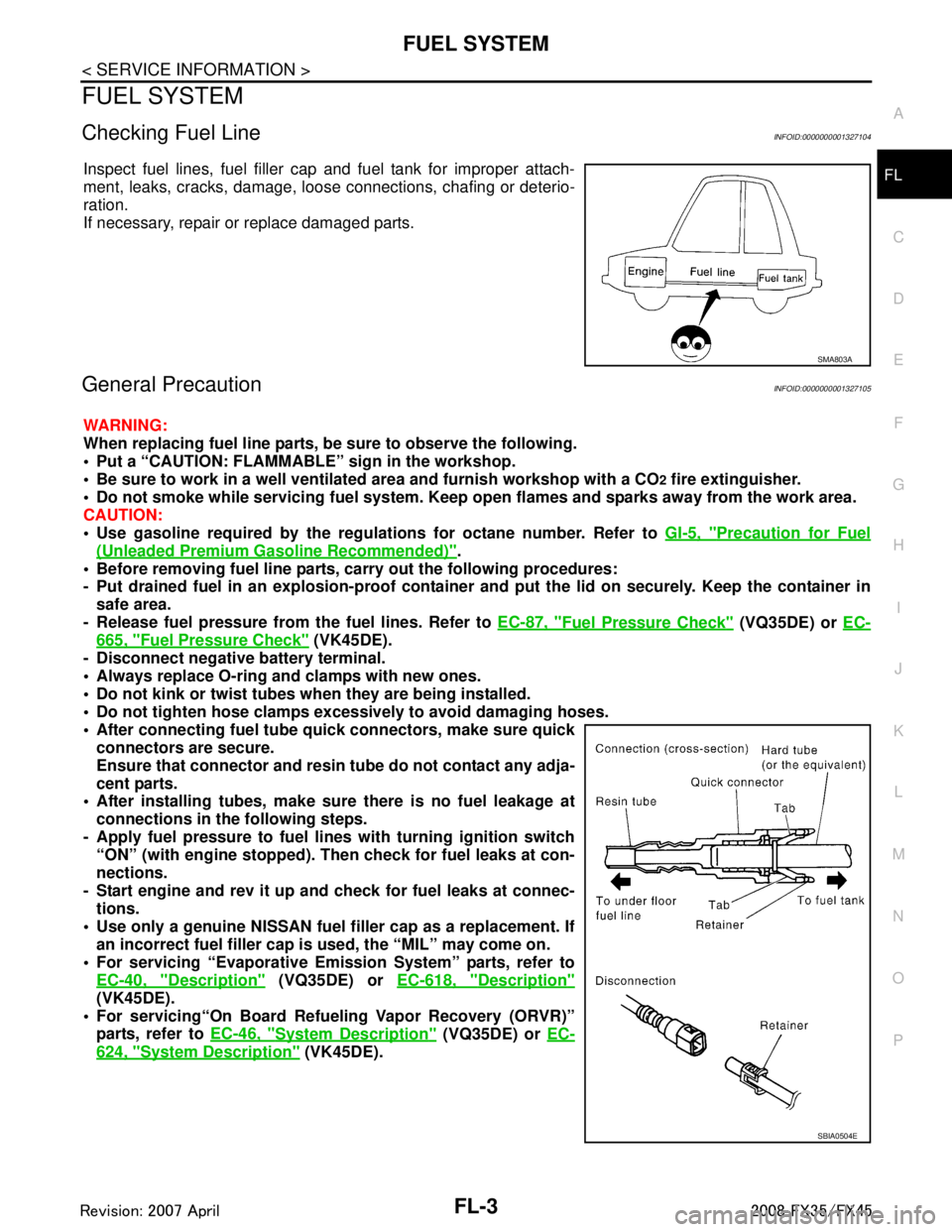
Inspect fuel lines, fuel filler cap and fuel tank for improper attach-
ment, leaks, cracks, damage, loos
e connections, chafing or deterio-
ration.
If necessary, repair or replace damaged parts.
General PrecautionINFOID:0000000001327105
WARNING:
When replacing fuel line parts, be sure to observe the following.
• Put a “CAUTION: FLAMMABLE” sign in the workshop.
Be sure to work in a well ventila ted area and furnish workshop with a CO
2 fire extinguisher.
Do not smoke while servicing fuel system. Keep open flames and sparks away from the work area.
CAUTION:
Use gasoline required by the regulations for octane number. Refer to GI-5, "
Precaution for Fuel
(Unleaded Premium Gasoline Recommended)".
Before removing fuel line parts, carry out the following procedures:
- Put drained fuel in an explosion-proof containe r and put the lid on securely. Keep the container in
safe area.
- Release fuel pressure from th e fuel lines. Refer to EC-87, "
Fuel Pressure Check" (VQ35DE) or EC-
665, "Fuel Pressure Check" (VK45DE).
- Disconnect negative battery terminal.
Always replace O-ring and clamps with new ones.
Do not kink or twist tubes when they are being installed.
Do not tighten hose clamps excessi vely to avoid damaging hoses.
After connecting fuel tube qu ick connectors, make sure quick
connectors are secure.
Ensure that connector and resin tube do not contact any adja-
cent parts.
After installing tubes, make su re there is no fuel leakage at
connections in the following steps.
- Apply fuel pressure to fuel li nes with turning ignition switch
“ON” (with engine stopped). Th en check for fuel leaks at con-
nections.
- Start engine and rev it up and check for fuel leaks at connec- tions.
Use only a genuine NISSAN fuel filler cap as a replacement. If
an incorrect fuel filler cap is used, the “MIL” may come on.
For servicing “Evaporative Emi ssion System” parts, refer to
EC-40, "
Description" (VQ35DE) or EC-618, "Description"
(VK45DE).
For servicing“On Board Refueling Vapor Recovery (ORVR)”
parts, refer to EC-46, "
System Description" (VQ35DE) or EC-
624, "System Description" (VK45DE).
SMA803A
SBIA0504E
3AA93ABC3ACD3AC03ACA3AC03AC63AC53A913A773A893A873A873A8E3A773A983AC73AC93AC03AC3
3A893A873A873A8F3A773A9D3AAF3A8A3A8C3A863A9D3AAF3A8B3A8C
Page 2840 of 3924

FL-8
< SERVICE INFORMATION >
FUEL LEVEL SENSOR UNIT, FUEL FILTER AND FUEL PUMP ASSEMBLY
1. Turn ignition switch “ON” (with engine stopped), then check connections for leaks by applying fuel pres-
sure to fuel piping.
2. Start engine and let it idle and make sure there are no fuel leaks at the fuel system connections.
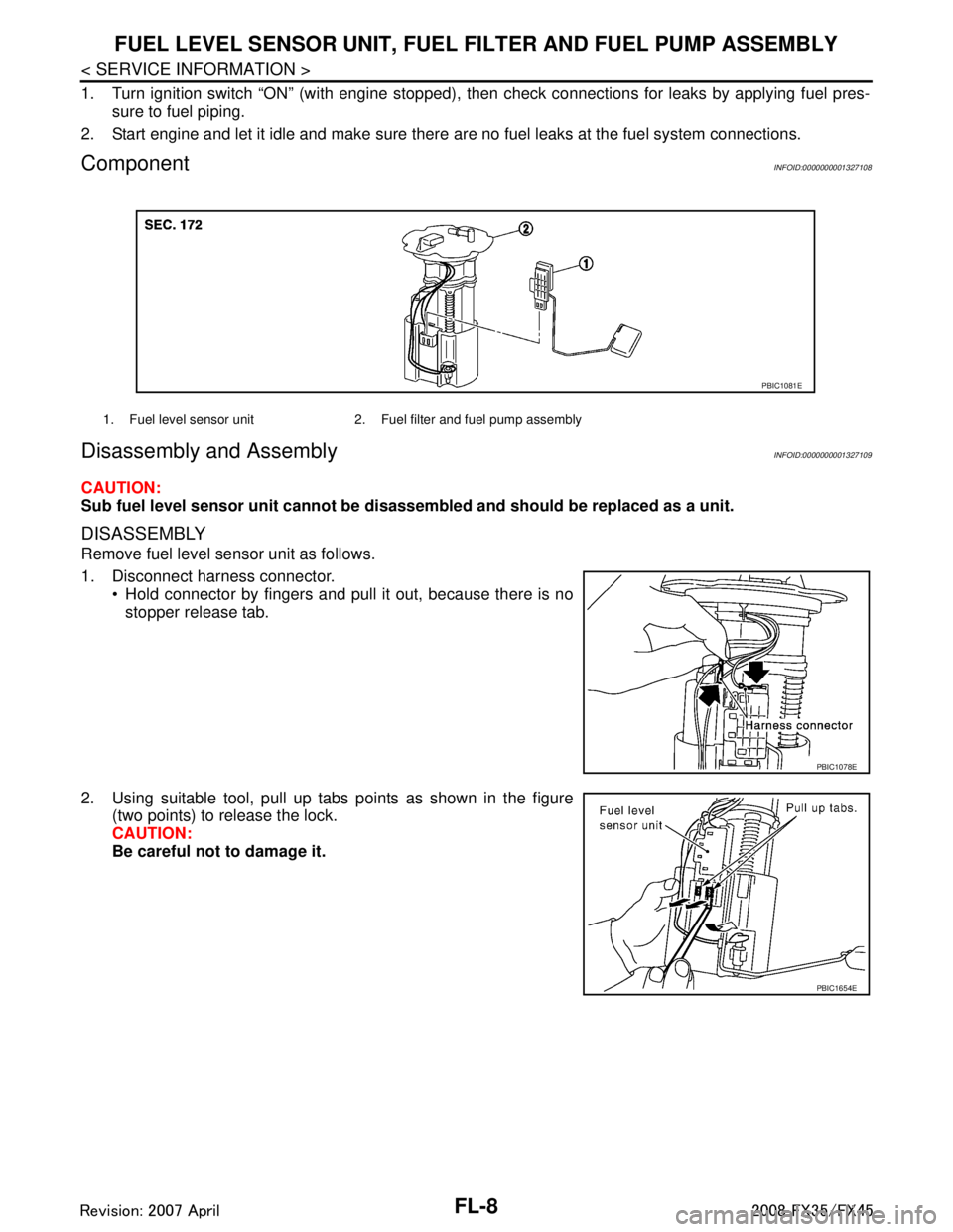
ComponentINFOID:0000000001327108
Disassembly and AssemblyINFOID:0000000001327109
CAUTION:
Sub fuel level sensor unit cannot be disassembled and should be replaced as a unit.
DISASSEMBLY
Remove fuel level sensor unit as follows.
1. Disconnect harness connector.
Hold connector by fingers and pull it out, because there is no
stopper release tab.
2. Using suitable tool, pull up tabs points as shown in the figure (two points) to release the lock.
CAUTION:
Be careful not to damage it.
1. Fuel level sensor unit 2. Fuel filter and fuel pump assembly
PBIC1081E
PBIC1078E
PBIC1654E
3AA93ABC3ACD3AC03ACA3AC03AC63AC53A913A773A893A873A873A8E3A773A983AC73AC93AC03AC3
3A893A873A873A8F3A773A9D3AAF3A8A3A8C3A863A9D3AAF3A8B3A8C
Page 2843 of 3924

FUEL TANKFL-11
< SERVICE INFORMATION >
C
DE
F
G H
I
J
K L
M A
FL
NP
O
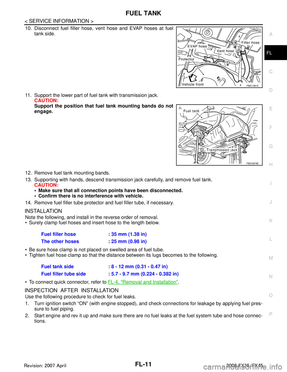
10. Disconnect fuel filler hose, v
ent hose and EVAP hoses at fuel
tank side.
11. Support the lower part of fuel tank with transmission jack. CAUTION:
Support the position that fuel tank mounting bands do not
engage.
12. Remove fuel tank mounting bands.
13. Supporting with hands, descend transmission jack carefully, and remove fuel tank. CAUTION:
Make sure that all connection points have been disconnected.
Confirm there is no interference with vehicle.
14. Remove fuel filler tube protector and fuel filler tube, if necessary.
INSTALLATION
Note the following, and install in the reverse order of removal.
Surely clamp fuel hoses and insert hose to the length below.
Be sure hose clamp is not placed on swelled area of fuel tube.
Tighten fuel hose clamp so that the distance between its lugs becomes to the following.
To connect quick connector, refer to FL-4, "
Removal and Installation".
INSPECTION AFTER INSTALLATION
Use the following procedure to check for fuel leaks.
1. Turn ignition switch “ON” (with engine stopped), and check connections for leakage by applying fuel pres-
sure to fuel piping.
2. Start engine and rev it up and make sure there are no fuel leaks at the fuel system tube and hose connec-
tions.
PBIC1581E
PBIC0878E
Fuel filler hose : 35 mm (1.38 in)
The other hoses : 25 mm (0.98 in)
Fuel tank side : 8 - 12 mm (0.31 - 0.47 in)
Fuel filler tube side : 5.7 - 9.7 mm (0.224 - 0.382 in)
3AA93ABC3ACD3AC03ACA3AC03AC63AC53A913A773A893A873A873A8E3A773A983AC73AC93AC03AC3
3A893A873A873A8F3A773A9D3AAF3A8A3A8C3A863A9D3AAF3A8B3A8C
Page 2864 of 3924

GI-2
< SERVICE INFORMATION >
PRECAUTIONS
SERVICE INFORMATION
PRECAUTIONS
DescriptionINFOID:0000000001325649
Observe the following precautions to ensure safe and proper servicing. These precautions are not
described in each individual section.
Precaution for Supplemental Restraint S ystem (SRS) "AIR BAG" and "SEAT BELT
PRE-TENSIONER"
INFOID:0000000001612904
The Supplemental Restraint System such as “A IR BAG” and “SEAT BELT PRE-TENSIONER”, used along
with a front seat belt, helps to reduce the risk or severi ty of injury to the driver and front passenger for certain
types of collision. This system includes seat belt switch inputs and dual stage front air bag modules. The SRS
system uses the seat belt switches to determine the front air bag deployment, and may only deploy one front
air bag, depending on the severity of a collision and w hether the front occupants are belted or unbelted.
Information necessary to service the system safely is included in the “SUPPLEMENTAL RESTRAINT SYS-
TEM” and “SEAT BELTS” of this Service Manual.
WARNING:
• To avoid rendering the SRS inopera tive, which could increase the risk of personal injury or death in
the event of a collision which would result in air bag inflation, all maintenance must be performed by
an authorized NISS AN/INFINITI dealer.
Improper maintenance, including in correct removal and installation of the SRS, can lead to personal
injury caused by unintent ional activation of the system. For re moval of Spiral Cable and Air Bag
Module, see the “SUPPLEMEN TAL RESTRAINT SYSTEM”.
Do not use electrical test equipmen t on any circuit related to the SRS unless instructed to in this
Service Manual. SRS wiring harnesses can be identi fied by yellow and/or orange harnesses or har-
ness connectors.
Precaution Necessary for Steering W heel Rotation After Battery Disconnect
INFOID:0000000001612934
NOTE:
This Procedure is applied only to models with In telligent Key system and NVIS/IVIS (NISSAN/INFINITI
VEHICLE IMMOBILIZER SYSTEM - NATS).
Remove and install all control units after disconnecting both battery cables with the ignition knob in the ″LOCK ″ position.
Always use CONSULT-III to perform self-diagnosis as a part of each function inspection after finishing work.
If DTC is detected, perform trouble diagnosis according to self-diagnostic results.
For models equipped with the Intelligent Key system and NVIS /IVIS, an electrically controlled steering lock
mechanism is adopted on the key cylinder.
For this reason, if the battery is disconnected or if the battery is discharged, the steering wheel will lock and
steering wheel rotation will become impossible.
If steering wheel rotation is required when battery pow er is interrupted, follow the procedure below before
starting the repair operation.
OPERATION PROCEDURE
1. Connect both battery cables. NOTE:
Supply power using jumper cables if battery is discharged.
2. Use the Intelligent Key or mechanical key to turn the ignition switch to the ″ACC ″ position. At this time, the
steering lock will be released.
3. Disconnect both battery cables. The steering lock will remain released and the steering wheel can be
rotated.
4. Perform the necessary repair operation.
5. When the repair work is completed, return the ignition switch to the ″LOCK ″ position before connecting
the battery cables. (At this time, the steering lock mechanism will engage.)
6. Perform a self-diagnosis check of all control units using CONSULT-III.
3AA93ABC3ACD3AC03ACA3AC03AC63AC53A913A773A893A873A873A8E3A773A983AC73AC93AC03AC3
3A893A873A873A8F3A773A9D3AAF3A8A3A8C3A863A9D3AAF3A8B3A8C