2008 INFINITI FX35 ignition switch
[x] Cancel search: ignition switchPage 2865 of 3924
PRECAUTIONSGI-3
< SERVICE INFORMATION >
C
DE
F
G H
I
J
K L
M B
GI
N
O P
Precaution for Procedur e without Cowl Top CoverINFOID:0000000001612933
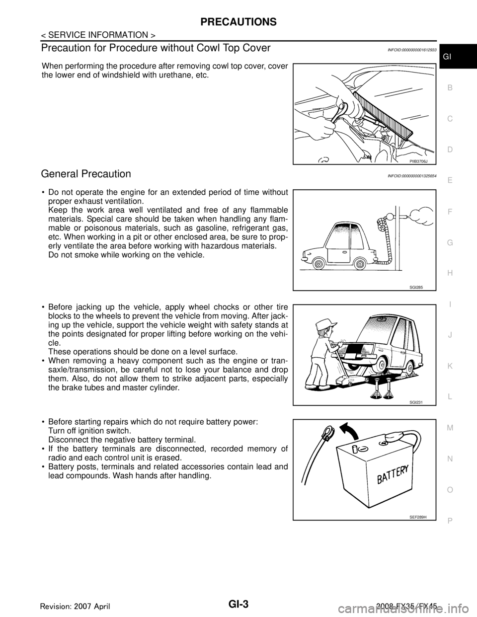
When performing the procedure after removing cowl top cover, cover
the lower end of windshield with urethane, etc.
General PrecautionINFOID:0000000001325654
Do not operate the engine for an extended period of time without
proper exhaust ventilation.
Keep the work area well ventilated and free of any flammable
materials. Special care should be taken when handling any flam-
mable or poisonous materials, such as gasoline, refrigerant gas,
etc. When working in a pit or ot her enclosed area, be sure to prop-
erly ventilate the area before working with hazardous materials.
Do not smoke while working on the vehicle.
Before jacking up the vehicle, apply wheel chocks or other tire
blocks to the wheels to prevent the vehicle from moving. After jack-
ing up the vehicle, support the vehicle weight with safety stands at
the points designated for proper lifting before working on the vehi-
cle.
These operations should be done on a level surface.
When removing a heavy component such as the engine or tran- saxle/transmission, be careful not to lose your balance and drop
them. Also, do not allow them to strike adjacent parts, especially
the brake tubes and master cylinder.
Before starting repairs which do not require battery power: Turn off ignition switch.
Disconnect the negative battery terminal.
If the battery terminals are disconnected, recorded memory of radio and each control unit is erased.
Battery posts, terminals and related accessories contain lead and
lead compounds. Wash hands after handling.
PIIB3706J
SGI285
SGI231
SEF289H
3AA93ABC3ACD3AC03ACA3AC03AC63AC53A913A773A893A873A873A8E3A773A983AC73AC93AC03AC3
3A893A873A873A8F3A773A9D3AAF3A8A3A8C3A863A9D3AAF3A8B3A8C
Page 2867 of 3924
PRECAUTIONSGI-5
< SERVICE INFORMATION >
C
DE
F
G H
I
J
K L
M B
GI
N
O P
Do not place the vehicle on flammable material. Keep flammable material off the exhaust pipe and the three
way catalyst.
Precaution for Fuel (Unlead ed Premium Gasoline Recommended)INFOID:0000000001325656
VQ35DE
INFINITI recommends the use of unleaded premium gasoli ne with an octane rating of at least 91 AKI (Anti-
Knock Index) number (Research octane number 96).
If unleaded premium gasoline is not available, you may use unleaded regular gasoline with an octane rating of
at least 87AKI number (Research octane number 91), but you may notice a decrease in performance.
CAUTION:
Do not use leaded gasoli ne. Using leaded gasoline will damage the three way catalyst. Do not use E-85
fuel (85% fuel ethanol, 15% unlead ed gasoline) unless the vehicle is specifically designed for E-85 fuel
(i.e. Flexible Fuel Vehicle - FFV models). Using a fu el other than that specified could adversely affect
the emission control devices and systems, and could also affect the warranty coverage validity.
Precaution for Fuel (Unleaded Premium Gasoline Required)INFOID:0000000001325657
VK45DE
Use unleaded premium gasoline with an octane rating of at least 91 AKI (Anti-Knock Index) number (Research
octane number 96).
If unleaded premium gasoline is not available, unleaded r egular gasoline with an octane rating of at least 87
AKI number (Research octane number 91) can be us ed, but only under the following precautions:
have the fuel tank filled only partially with unl eaded regular gasoline, and fill up with unleaded premium gas-
oline as soon as possible.
avoid full throttle driving and abrupt acceleration.
However, for maximum vehicle performance, the u se of unleaded premium gasoline is recommended.
CAUTION:
Do not use leaded gasoli ne. Using leaded gasoline will damage the three way catalyst. Do not use E-85
fuel (85% fuel ethanol, 15% unlead ed gasoline) unless the vehicle is specifically designed for E-85 fuel
(i.e. Flexible Fuel Vehicle - FFV models). Using a fu el other than that specified could adversely affect
the emission control devices and systems, and could also affect the warranty coverage validity.
Precaution for Multiport Fuel Inject ion System or Engine Control SystemINFOID:0000000001325658
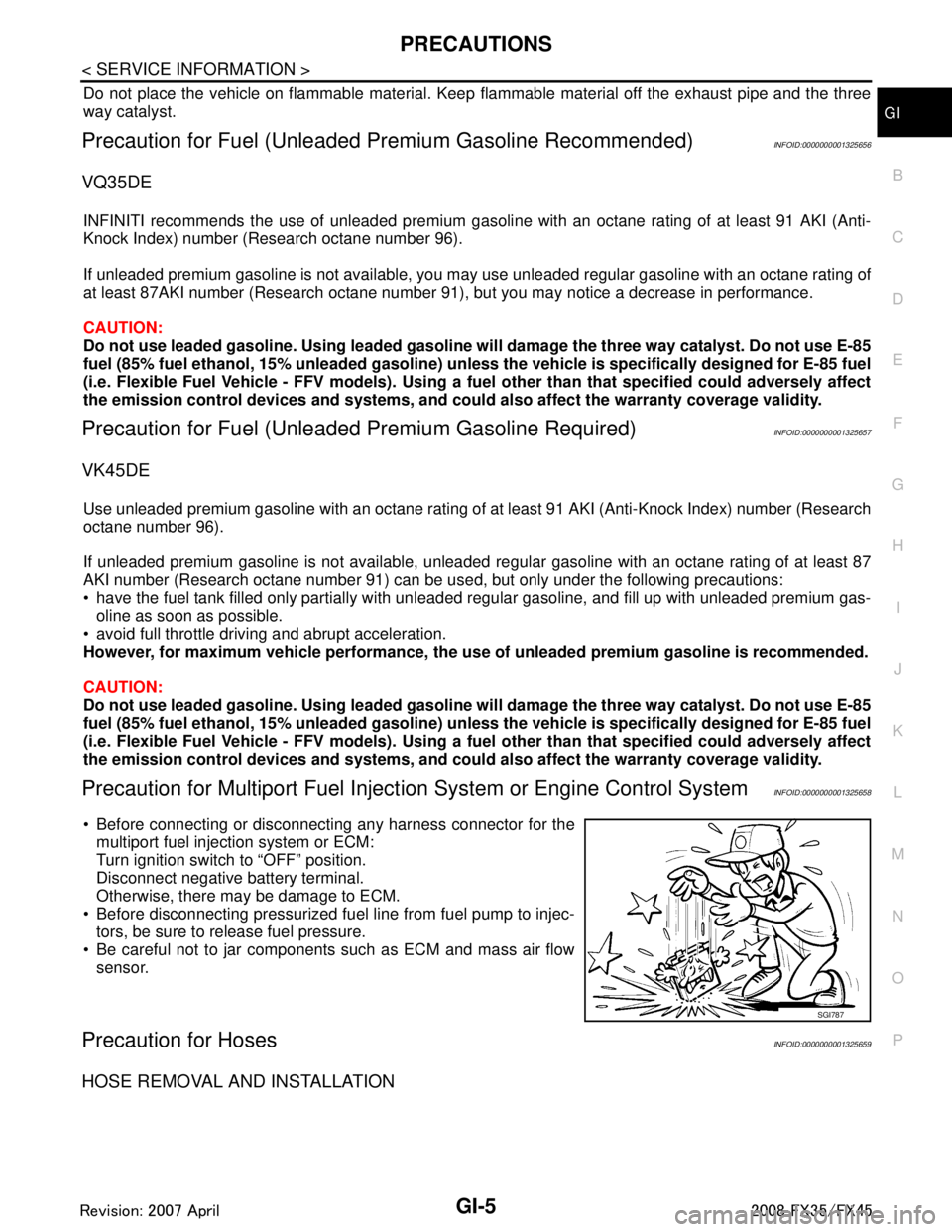
Before connecting or disconnecti ng any harness connector for the
multiport fuel injection system or ECM:
Turn ignition switch to “OFF” position.
Disconnect negative battery terminal.
Otherwise, there may be damage to ECM.
Before disconnecting pressurized fuel line from fuel pump to injec- tors, be sure to release fuel pressure.
Be careful not to jar components such as ECM and mass air flow sensor.
Precaution for HosesINFOID:0000000001325659
HOSE REMOVAL AND INSTALLATION
SGI787
3AA93ABC3ACD3AC03ACA3AC03AC63AC53A913A773A893A873A873A8E3A773A983AC73AC93AC03AC3
3A893A873A873A8F3A773A9D3AAF3A8A3A8C3A863A9D3AAF3A8B3A8C
Page 2872 of 3924
GI-10
< SERVICE INFORMATION >
HOW TO USE THIS MANUAL
3.Refer to Component Parts and Harness Connector Location for the Systems described in each
section for identifi cation/location of componen ts and harness connectors.
4. Refer to the Circuit Diagra m for quick pinpoint check.
If you need to check circuit continuity between harness connectors in more detail, such as when a
sub-harness is used, refer to Wiring Diagram in each individual section and Harness Layout in PG
section for identificatio n of harness connectors.
5. When checking circuit continuity, ignition switch should be OFF.
6. Before checking voltage at co nnectors, check battery voltage.
7. After accomplishing the Diagnost ic Procedures and Electrical Components Inspection, make sure
that all harness connectors ar e reconnected as they were.
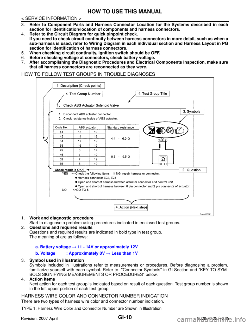
HOW TO FOLLOW TEST GROUPS IN TROUBLE DIAGNOSES
1.Work and diagnostic procedure
Start to diagnose a problem using procedures indicated in enclosed test groups.
2. Questions and required results
Questions and required results are indicated in bold type in test group.
The meaning of are as follows:
3. Symbol used in illustration
Symbols included in illustrations refer to measur ements or procedures. Before diagnosing a problem,
familiarize yourself with each symbol. Refer to "Connector Symbols" in GI Section and "KEY TO SYM-
BOLS SIGNIFYING MEASUREME NTS OR PROCEDURES" below.
4. Action items
Next action for each test group is indicated based on result of each question. Test group number is shown
in the left upper portion of each test group.
HARNESS WIRE COLOR AND CONNECTOR NUMBER INDICATION
There are two types of harness wire color and connector number indication.
TYPE 1: Harness Wire Color and Connec tor Number are Shown in Illustration
SAIA0256E
a. Battery voltage → 11 - 14V or approximately 12V
b. Voltage : Approximately 0V → Less than 1V
3AA93ABC3ACD3AC03ACA3AC03AC63AC53A913A773A893A873A873A8E3A773A983AC73AC93AC03AC3
3A893A873A873A8F3A773A9D3AAF3A8A3A8C3A863A9D3AAF3A8B3A8C
Page 2880 of 3924
GI-18
< SERVICE INFORMATION >
HOW TO USE THIS MANUAL
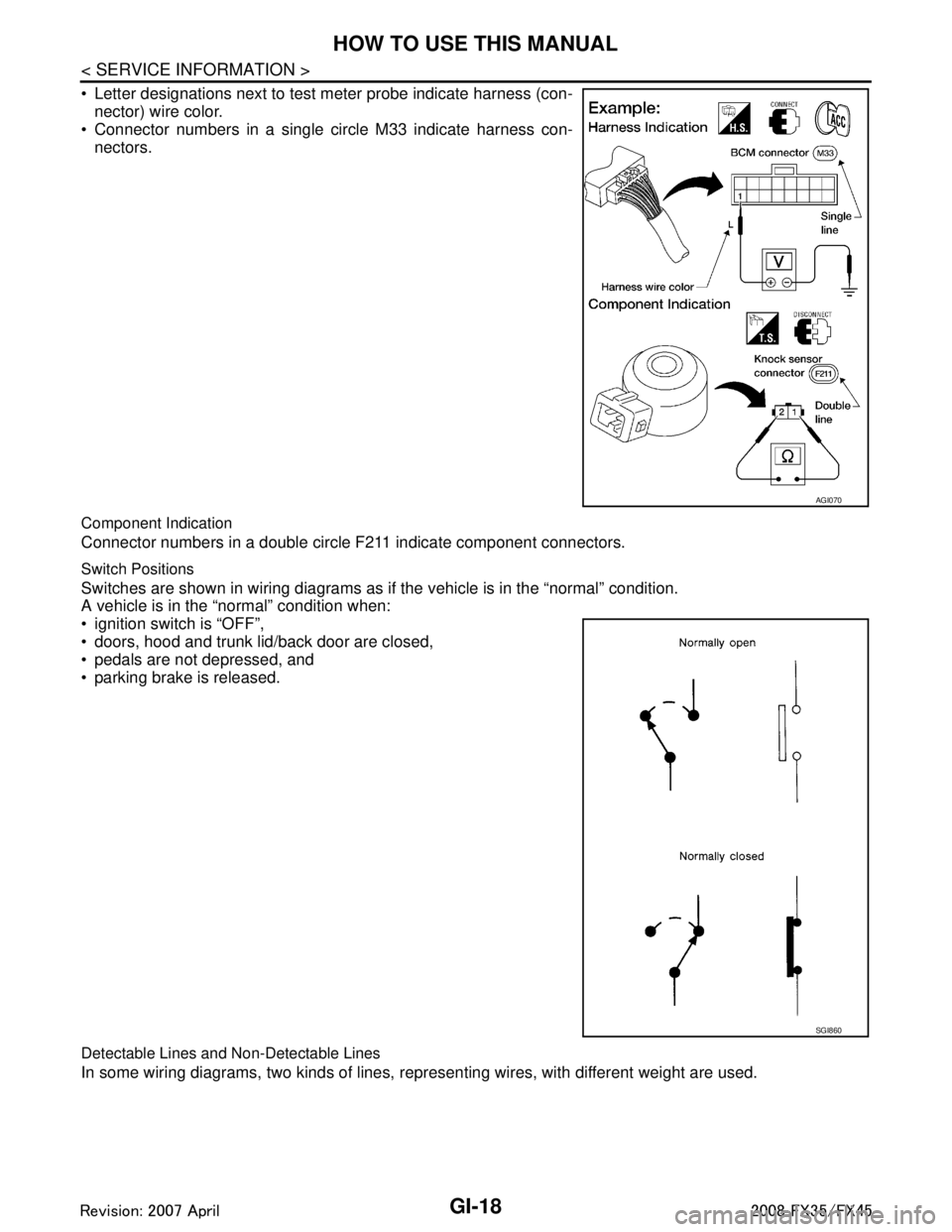
Letter designations next to test meter probe indicate harness (con-nector) wire color.
Connector numbers in a single circle M33 indicate harness con-
nectors.
Component Indication
Connector numbers in a double circle F211 indicate component connectors.
Switch Positions
Switches are shown in wiring diagrams as if the vehicle is in the “normal” condition.
A vehicle is in the “normal” condition when:
ignition switch is “OFF”,
doors, hood and trunk lid/back door are closed,
pedals are not depressed, and
parking brake is released.
Detectable Lines and Non-Detectable Lines
In some wiring diagrams, two kinds of lines, r epresenting wires, with different weight are used.
AGI070
SGI860
3AA93ABC3ACD3AC03ACA3AC03AC63AC53A913A773A893A873A873A8E3A773A983AC73AC93AC03AC3
3A893A873A873A8F3A773A9D3AAF3A8A3A8C3A863A9D3AAF3A8B3A8C
Page 2910 of 3924

GI-48
< SERVICE INFORMATION >
TERMINOLOGY
TERMINOLOGY
SAE J1930 Terminology ListINFOID:0000000001325691
All emission related terms used in this publication in accordance with SAE J1930 are listed. Accordingly, new
terms, new acronyms/abbreviations and old te rms are listed in the following chart.
NEW TERMNEW ACRONYM /
ABBREVIATION OLD TERM
Air cleaner ACL Air cleaner
Barometric pressure BARO ***
Barometric pressure sensor-BCDD BAROS-BCDD BCDD
Camshaft position CMP ***
Camshaft position sensor CMPS Crank angle sensor
Canister *** Canister
Carburetor CARB Carburetor
Charge air cooler CAC Intercooler
Closed loop CL Closed loop
Closed throttle position switch CTP switch Idle switch
Clutch pedal position switch CPP switch Clutch switch
Continuous fuel injection system CFI system ***
Continuous trap oxidizer system CTOX system ***
Crankshaft position CKP ***
Crankshaft position sensor CKPS ***
Data link connector DLC ***
Data link connector for CONS ULT-II DLC for CONSULT-II Diagno stic connector for CONSULT-II
Diagnostic test mode DTM Diagnostic mode
Diagnostic test mode selector DTM selector Diagnostic mode selector
Diagnostic test mode I DTM I Mode I
Diagnostic test mode II DTM II Mode II
Diagnostic trouble code DTC Malfunction code
Direct fuel injection system DFI system ***
Distributor ignition system DI system Ignition timing control
Early fuel evaporation-mixture heater EFE-mixture heater Mixture heater
Early fuel evaporation system EFE system Mixture heater control
Electrically erasable programmable read
only memory EEPROM ***
Electronic ignition system EI system Ignition timing control
Engine control EC ***
Engine control module ECM ECCS control unit
Engine coolant temperature ECT Engine temperature
Engine coolant temperature sensor ECTS Engine temperature sensor
Engine modification EM ***
Engine speed RPM Engine speed
Erasable programmable read only memory EPROM ***
Evaporative emission canister EVAP canister Canister
Evaporative emission system EVAP system Canister control solenoid valve
Exhaust gas recirculation valve EGR valve EGR valve
3AA93ABC3ACD3AC03ACA3AC03AC63AC53A913A773A893A873A873A8E3A773A983AC73AC93AC03AC3
3A893A873A873A8F3A773A9D3AAF3A8A3A8C3A863A9D3AAF3A8B3A8C
Page 2929 of 3924

GW-16
< SERVICE INFORMATION >
POWER WINDOW SYSTEM
to power window main switch terminal 19
to front power window switch (passenger side) terminal 10.
through 15A fuse [No. 22, located in the fuse block (J/B)]
to BCM terminal 42.
With ignition switch in ON or START position,
Power is supplied
through 15A fuse [No. 1, located in the fuse block (J/B)]
to BCM terminal 38, and
trough BCM terminal 53
to power window main switch terminal 10
to rear power window switch (LH and RH) terminal 1.
Ground supplied
to BCM terminal 49 and 52
through body grounds M35, M45 and M85.
to power window main switch terminal 17
through body grounds M35, M45 and M85.
to front power window switch (passenger side) terminal 11
through body grounds M35, M45 and M85.
MANUAL OPERATION
Front Driver Side Door
WINDOW UP
When the front LH switch in the power window main switch is pressed in the up position,
Power is supplied
through power window main switch terminal 8
to front power window motor (driver side) terminal 2.
Ground is supplied
to front power window motor (driver side) terminal 1
through power window main switch terminal 11.
Then, the motor raises the window until the switch is released.
WINDOW DOWN
When the front LH switch in the power window main switch is pressed in the down position
Power is supplied
through power window main switch terminal 11
to front power window motor (driver side) terminal 1.
Ground is supplied
to front power window motor (driver side) terminal 2
through power window main switch terminal 8.
Then, the motor lowers the window until the switch is released.
Front Passenger Side Door
FRONT POWER WINDOW SWITCH (P ASSENGER SIDE) OPERATION
WINDOW UP
When the front power window switch (pass enger side) is pressed in the up position
Power is supplied
through front power window switch (passenger side) terminal 8
to front power window motor (passenger side) terminal 2.
Ground is supplied
to front power window motor (passenger side) terminal 1
through front power window switch (passenger side) terminal 9.
Then, the motor raises the window until the switch is released.
WINDOW DOWN
When the front power window switch (passenger side) is pressed in the down position
Power is supplied
through front power window switch (passenger side) terminal 9
to front power window motor (passenger side) terminal 1.
Ground is supplied
to front power window motor (passenger side) terminal 2
through front power window switch (passenger side) terminal 8.
Then, the motor lowers the window until the switch is released.
POWER WINDOW MAIN SWITCH OPERATION
3AA93ABC3ACD3AC03ACA3AC03AC63AC53A913A773A893A873A873A8E3A773A983AC73AC93AC03AC3
3A893A873A873A8F3A773A9D3AAF3A8A3A8C3A863A9D3AAF3A8B3A8C
Page 2931 of 3924
GW-18
< SERVICE INFORMATION >
POWER WINDOW SYSTEM
The one is applied only for front doors and the other is for all doors.
POWER WINDOW SERIAL LINK
Power window main switch, front power window switch (passenger side), and BCM transmit and receive the
signal by power window serial link.
The under mentioned signal is transmitted from BCM to power window main switch and front power window
switch (passenger side)
Keyless power window down signal.
The under mentioned signal is transmitted from power window main switch to front power window switch (pas-
senger side)
Front passenger side door window operation signal.
Power window control by key cylinder switch signal.
Power window lock signal.
Retained power operation signal.
POWER WINDOW LOCK
The power window lock is designed to lock operation of all windows except for driver side door window.
When the lock position, ground of the rear power window switches in the power window main switch is discon-
nected. The power window lock signal is transmitted to front power window switch (passenger side) by power
window serial link. This prevents t he power window motors from operating.
RETAINED POWER OPERATION
When the ignition switch is turned to the OFF position from ON or START position.
Power is supplied for 45 seconds
through BCM terminal 53
to power window main switch terminal 10
to rear power window switch (LH and RH) terminals 1.
When power and ground are supplied, the BCM conti nues to be energized, and the power window can be
operated.
The retained power operation is canceled when the driver or passenger side door is opened.
RAP signal period can be changed by CONSULT-III. Refer to GW-26, "
CONSULT-III Function".
ANTI-PINCH SYSTEM
Power window main switch and front power window switch (passenger side) monitors the power window motor
operation and the power window position (full closed or other) for driver side and passenger side power win-
dow by the signals from encoder and limit switch in front power window motor (driver side and passenger
side).
When power window main switch detects inte rruption during the following close operation,
automatic close operation when igniti on switch is in the “ON” position
automatic close operation during retained power operation
manual close operation during retained power operation
power window main switch or front power window swit ch (passenger side) controls each power window motor
for open and the power window will be lowered about 150 mm (5.91 in).
POWER WINDOW CONTROL BY THE KEY CYLINDER SWITCH
When ignition key switch is OFF, front power window can be opened or closed by turning the key cylinder
switch UNLOCK / LOCK position more than 1.5 second over condition.
Power window can be opened as the door key cylinder is kept fully turning to the UNLOCK position.
Power window can be closed as the door key cylinder is kept fully turning to the LOCK position.
The power window DOWN stops when the following operations are carried out.
While performing open / close the window, power window is stopped at the position as the door key cylinder is placed on NEUTRAL.
When the ignition switch is turned ON while the power window DOWN is operated.
CAN Communication System DescriptionINFOID:0000000001327964
CAN (Controller Area Network) is a serial communication line for real time application. It is an on-vehicle mul-
tiplex communication line with high data communication s peed and excellent error detection ability. Many elec-
tronic control units are equipped onto a vehicle, and each control unit shares information and links with other
control units during operation (not independent). In CA N communication, control units are connected with 2
communication lines (CAN H line, CAN L line) allowing a high rate of information transmission with less wiring.
Each control unit transmits/receives data but selectively reads required data only.
3AA93ABC3ACD3AC03ACA3AC03AC63AC53A913A773A893A873A873A8E3A773A983AC73AC93AC03AC3
3A893A873A873A8F3A773A9D3AAF3A8A3A8C3A863A9D3AAF3A8B3A8C
Page 2937 of 3924

GW-24
< SERVICE INFORMATION >
POWER WINDOW SYSTEM
Terminal and Reference Value for Power Window Main Switch
INFOID:0000000001327969
22 OR Power window serial link Input/Output IGN SW ON or power window
timer operating.
38 W/L Ignition switch
(ON or START) InputIgnition switch
(ON or START position) Battery voltage
39 L CAN - H Input/Output — —
40 P CAN - L Input/Output — —
42 L/R Power source (Fuse) Input — Battery voltage
49 B Ground (signal) — — 0
52 B Ground (power) — — 0
53 Y/B Rap signal Output IGN SW ON Battery voltage
Within 45 second after ignition
switch is turned to OFF
Battery voltage
When driver side or passen-
ger side door is open in power
window timer is operates 0
54 W Power window power supply Output — Battery voltage
55 G Power source
(Fusible link)
Input — Battery voltage
62 W Front door switch
driver side signal InputON (Open) 0
OFF (Close) Battery voltage
Te r -
minal Wire
color Item Signal
Input/Output Condition Voltage [V]
(Approx.)
PIIA2344J
Te r -
minal Wire
color Item Signal
Input/Output Condition Voltage [V]
(Approx.)
1Y Rear LH power window
UP signal OutputWhen rear LH switch in
power window main switch is
UP at operated. Battery voltage
2SB Limit switch and encoder
ground —— 0
3R Rear LH power window
DOWN signal OutputWhen rear LH switch in
power window main switch is
DOWN at operated. Battery voltage
4P Door key cylinder switch
LOCK signal InputKey position
(Neutral
→ Locked) 5
→ 0
5G Rear RH power window
DOWN signal OutputWhen rear RH switch in
power window main switch is
DOWN at operated. Battery voltage
6OR Door key cylinder switch
UNLOCK signal Input
Key position
(Neutral
→ Unlocked) 5
→ 0
7LG Rear RH power window
UP signal OutputWhen rear RH switch in
power window main switch is
UP at operated. Battery voltage
8L Front driver side
power window motor UP signal
OutputWhen front LH switch in
power window main switch is
UP at operated
Battery voltage
3AA93ABC3ACD3AC03ACA3AC03AC63AC53A913A773A893A873A873A8E3A773A983AC73AC93AC03AC3
3A893A873A873A8F3A773A9D3AAF3A8A3A8C3A863A9D3AAF3A8B3A8C