2008 INFINITI FX35 spare wheel
[x] Cancel search: spare wheelPage 3 of 3924

QUICK REFERENCE CHART FX35/FX45
ENGINE TUNE-UP DATA (VK45DE)
FRONT WHEEL ALIGNMENT (Unladen* )
ELS0003X
* : Fuel, engine coolant and engine oil full. Spare tire, jack, hand tools and mats in designated positions.Engine modelVK45DE
Firing order1-8-7-3-6-5-4-2
Idle speed
A/T (In “P” or “N” position) rpm650 ± 50
Ignition timing (BTDC at idle speed)
A/T (In “P” or “N” position)12° ± 5°
Tensions of drive belts Auto adjustment by auto tensioner
Radiater cap relief pressure
kPa (kg/cm
2 , psi)
78 - 98 (0.8-1.0 , 11-14) Standard
Limit 59 (0.6, 9)
Cooling system leakage testing pressure
157 (1.6, 23)
kPa (kg/cm
2 , psi)
Compression pressure
kPa (kg/cm
2 , psi)/rpm
1,320 (13.5, 191) /300 Standard
Minimum 1,130 (11.5, 164) /300
Spark plug Standard type PLFR5A-11
Hot type PLFR4A-11
Cold type PLFR6A-11
Camber Degree minute (Decimal degree) Minimum –1° 29′ (–1.48°)
Nominal –0° 44′ (–0.73°)
Maximum 0° 01′ (0.02°)
Left and right difference 45′ (0.75°) or less
Caster Degree minute (Decimal degree) Minimum 3° 02′ (3.03°)
Nominal 3° 47′ (3.78°)
Maximum 4° 32′ (4.53°)
Left and right difference 45′ (0.75°) or less
Kingpin inclination Degree minute (Decimal degree) Minimum 12° 20′ (12.33°)
Nominal 13° 05′ (13.08°)
Maximum 13° 50′ (13.83°)
Total toe-in Distance Minimum 0.6 mm (0.024 in)
Nominal 1.6 mm (0.063 in)
Maximum 2.6 mm (0.102 in)
Angle (left wheel or right wheel)
Degree minute (Decimal degree)Minimum 0° 01′ (0.02°)
Nominal 0° 04′ (0.06°)
Maximum 0° 06′ (0.10°)
Wheel turning angle (Full turn) Inside Minimum 32° 00 (32.0°)
Degree minute (Decimal degree) Nominal 35° 00 (35.0°)
Maximum 36° 00 (36.0°)
Outside
Nominal 30° 00 (30.0°)
Degree minute (Decimal degree)
2008
Page 4 of 3924

QUICK REFERENCE CHART FX35/FX45
REAR WHEEL ALIGNMENT (Unladen*)
ELS0003Y
* : Fuel, engine coolant and engine oil full. Spare tire, jack, hand tools and mats in designated positions.
BRAKEELS0003Z
* : Under force of 490 N (50 kg, 110 lb) with engine running.
REFILL CAPACITIESELS00040
Camber
Degree minute (Decimal degree)Minimum –1° 18′ (–1.30°)
Nominal –0° 48′ (–0.80°)
Maximum – 0° 18′ (– 0.30°)
Total toe-inDistance Minimum 2.4 mm (0.09 in)
Nominal 4.7 mm (0.19 in)
Maximum 7.0 mm (0.28 in)
Angle (left wheel or right wheel)
Degree minute (Decimal degree)Minimum 0° 05′ (0.08°)
Nominal 0° 10′ (0.17°)
Maximum 0° 15′ (0.25°)
Front brake Pad repair limit 2.0 mm (0.079 in)
Rotor wear limit 32.0 mm (1.260 in)
Rear brake Pad repair limit 2.0 mm (0.079 in)
Rotor wear limit 14.0 mm (0.551 in)
Pedal free height 161.5 - 171.5 mm (6.358 - 6.752 in)
Pedal depressed height* More than 95 mm (3.74 in)
UNITLiter US measure
Fuel tank90 23 - 3/4 gal
Coolant (With reservoir tank)VQ35DE 8.6 9 - 1/8 qt
VK45DE 10.0 10 - 5/8 qt
Engine (VQ35DE)Drain and refill
With oil filter change 4.7 5 qt
Without oil filter change 4.4 4 - 5/8 qt
Dry engine (Overhaul) 5.4 5 - 3/4 qt
Engine (VK45DE)Drain and refill
With oil filter change 5.8 6 - 1/8 qt
Without oil filter change 5.2 5 - 1/2 qt
Dry engine (Overhaul) 7.0 7 - 3/8 qt
Transmission A/T 10.3 10 - 7/8 qt
Transfer1.25 2 - 5/8 pt
Differential carrierFront 0.65 1 - 3/8 pt
Rear 1.4 3 pt
Power steering system 1.0 1 - 1/8 qt
Air conditioning systemCompressor oil 0.18 6.0 fl oz
Refrigerant 0.55 kg 1.21 lb
2008
Page 2483 of 3924

EI-46
< SERVICE INFORMATION >
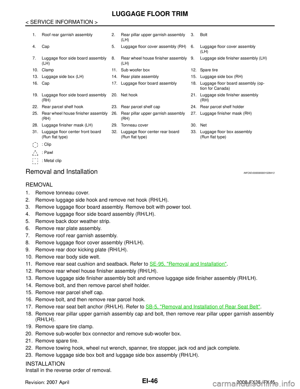
LUGGAGE FLOOR TRIM
Removal and Installation
INFOID:0000000001529413
REMOVAL
1. Remove tonneau cover.
2. Remove luggage side hook and remove net hook (RH/LH).
3. Remove luggage floor board assembly. Remove bolt with power tool.
4. Remove luggage floor side board assembly (RH/LH).
5. Remove back door weather strip.
6. Remove rear plate assembly.
7. Remove roof rear garnish assembly.
8. Remove luggage floor cover assembly (RH/LH).
9. Remove rear door kicking plate (RH/LH).
10. Remove rear body side welt.
11. Remove rear seat cushion and seatback. Refer to SE-95, "
Removal and Installation".
12. Remove rear wheel house finisher assembly (RH/LH).
13. Remove luggage side finisher assembly bolt and remove luggage side finisher assembly (RH/LH).
14. Remove bolt, and then remove parcel shelf holder.
15. Remove rear parcel shelf cap.
16. Remove bolt, and then remove rear parcel hook.
17. Remove rear seat belt anchor (RH/LH). Refer to SB-5, "
Removal and Installation of Rear Seat Belt".
18. Remove rear pillar upper garnish assembly cap and bolt, then remove rear pillar upper garnish assembly (RH/LH).
19. Remove spare tire clamp.
20. Remove sub-woofer box connector and remove sub-woofer box.
21. Remove spare tire.
22. Remove towing hook, wheel nut wrench, spanner, tire stopper, jack rod and jack complete.
23. Remove luggage side box bolt and luggage side box assembly (RH/LH).
INSTALLATION
Install in the reverse order of removal.
1. Roof rear garnish assembly 2. Rear pillar upper garnish assembly (LH)3. Bolt
4. Cap 5. Luggage floor cover assembly (RH) 6. Luggage floor cover assembly (LH)
7. Luggage floor side board assembly (LH) 8. Rear wheel house finisher assembly
(LH) 9. Luggage side finisher assembly (LH)
10. Clamp 11. Sub woofer box 12. Spare tire
13. Luggage side box (LH) 14. Rear plate assembly 15. Luggage side box (RH)
16. Cap 17. Luggage floor board assembly 18. Luggage floor board assembly (op- tion for Canada)
19. Luggage floor side board assembly (RH) 20. Net hook 21. Luggage side finisher assembly
(RH)
22. Rear parcel shelf hook 23. Rear parcel shelf cap 24. Rear parcel shelf holder
25. Rear wheel house finisher assembly (RH) 26. Rear pillar upper garnish assembly
(RH) 27. Luggage finisher mask (RH)
28. Luggage finisher mask (LH) 29. Tonneau cover 30. Net
31. Luggage floor center front board (Run flat type) 32. Luggage floor center rear board
(Run flat type) 33. Luggage floor box assembly
(Run flat type)
: Clip
: Pawl
: Metal clip
3AA93ABC3ACD3AC03ACA3AC03AC63AC53A913A773A893A873A873A8E3A773A983AC73AC93AC03AC3
3A893A873A873A8F3A773A9D3AAF3A8A3A8C3A863A9D3AAF3A8B3A8C
Page 2846 of 3924

FSU-2
< SERVICE INFORMATION >
PRECAUTIONS
SERVICE INFORMATION
PRECAUTIONS
CautionINFOID:0000000001327533
• When installing rubber bushings, final tightening must be carried out under unladen conditions with tires on
ground. Oil will shorten the life of rubber bushings. Be sure to wipe off any spilled oil.
Unladen conditions mean that fuel, engine coolant and l ubricant are full. Spare tire, jack, hand tools and
mats are in designated positions.
After servicing suspension parts, be sure to check wheel alignment.
Caulking nuts are not reusable. Always use new ones w hen installing. Since new caulking nuts are pre-oiled,
tighten as they are.
Avoid burden to front cross bar.
3AA93ABC3ACD3AC03ACA3AC03AC63AC53A913A773A893A873A873A8E3A773A983AC73AC93AC03AC3
3A893A873A873A8F3A773A9D3AAF3A8A3A8C3A863A9D3AAF3A8B3A8C
Page 2849 of 3924

FRONT SUSPENSION ASSEMBLYFSU-5
< SERVICE INFORMATION >
C
DF
G H
I
J
K L
M A
B
FSU
N
O P
FRONT SUSPENSION ASSEMBLY
On-Vehicle Inspection and ServiceINFOID:0000000001327537
Make sure the mounting conditions (looseness, back lash) of each component and component conditions
(wear, damage) are normal.
INSPECTION LOWER BALL JOINT END PLAY
1. Set front wheels in a straight-ahead position. Do not depress brake pedal.
2. Place an iron bar or similar tool bet ween transverse link and steering knuckle.
3. Measure axial end play by prying it up and down.
CAUTION:
Be careful not to damage ball joint boot.
STRUT INSPECTION
Check strut for oil leakage, damage and replace if there are. Refer to FSU-10.
Wheel Alignment InspectionINFOID:0000000001327538
DESCRIPTION
Measure wheel alignment under unladen conditions.
NOTE:
Unladen conditions mean that fuel, engine coolant, and l ubricant are full. Spare tire, jack, hand tools and
mats are designated positions.
PRELIMINARY CHECK
Check tires for improper air pressure and wear.
Check road wheels for runout.
Check wheel bearing axial end play.
Check ball joint axial end play of compression rod, upper link, and steering knuckle
Check shock absorber operation.
Check each mounting part of axle and suspension for looseness and deformation.
Check each link, rod and member for cracks, deformation and other damage.
Check vehicle posture.
GENERAL INFORMATION AND RECOMMENDATIONS
A four-wheel thrust alignment should be performed.
- This type of alignment is recomm ended for any NISSAN/INFINITI vehicle.
- The four-wheel “thrust” process helps ensure that t he vehicle is properly aligned and the steering wheel is
centered.
- The alignment rack itself should be capable of accepting any NISSAN/INFINITI vehicle.
- The rack should be checked to ensure that it is level.
Make sure the machine is properly calibrated.
- Your alignment equipment should be regularly ca librated in order to give correct information.
- Check with the manufacturer of your specific equi pment for their recommended Service/Calibration Sched-
ule.
THE ALIGNMENT PROCESS
IMPORTANT:
Use only the alignment specificati ons listed in this Service Manual.
When displaying the alignment settings, many alignment machines use “indicators”: (Green/red, plus or
minus, Go/No Go). Do NOT use these indicators.
- The alignment specifications programmed into your machine that operate these indicators may not be cor-
rect.
- This may result in an ERROR.
Some newer alignment machines are equipped with an optional “Rolling Compensation” method to “com-
pensate” the sensors (alignment targets or head units). DO NOT use this “Rolling Compensation”
method. Axial end play : 0 mm (0 in)
3AA93ABC3ACD3AC03ACA3AC03AC63AC53A913A773A893A873A873A8E3A773A983AC73AC93AC03AC3
3A893A873A873A8F3A773A9D3AAF3A8A3A8C3A863A9D3AAF3A8B3A8C
Page 2861 of 3924

SERVICE DATA AND SPECIFICATIONS (SDS)
FSU-17
< SERVICE INFORMATION >
C
D F
G H
I
J
K L
M A
B
FSU
N
O P
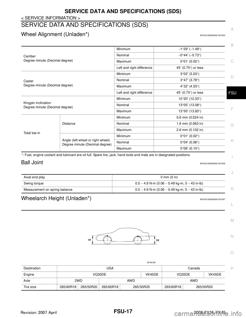
SERVICE DATA AND SPECIFICATIONS (SDS)
Wheel Alignment (Unladen*)INFOID:0000000001327545
*: Fuel, engine coolant and lubricant are oil full. Spare tire, jack, hand tools and mats are in designated positions.
Ball JointINFOID:0000000001327546
Wheelarch Height (Unladen*)INFOID:0000000001327547
Camber
Degree minute (Decimal degree) Minimum
−1 °29 ′ ( −1.48 °)
Nominal −0 °44 ′ ( −0.73 °)
Maximum 0 °01 ′ (0.02 °)
Left and right difference 45 ′ (0.75 °) or less
Caster
Degree minute (Decimal degree) Minimum 3
°02 ′ (3.03 °)
Nominal 3 °47 ′ (3.78 °)
Maximum 4 °32 ′ (4.53 °)
Left and right difference 45 ′ (0.75 °) or less
Kingpin inclination
Degree minute (Decimal degree) Minimum 12
°20 ′ (12.33 °)
Nominal 13 °05 ′ (13.08 °)
Maximum 13 °50 ′ (13.83 °)
Total toe-in Distance
Minimum 0.6 mm (0.024 in)
Nominal 1.6 mm (0.063 in)
Maximum 2.6 mm (0.102 in)
Angle (left wheel or right wheel)
Degree minute (Decimal degree) Minimum 0
°01 ′ (0.02 °)
Nominal 0
° 04 ′ (0.06 °)
Maximum 0 °06 ′ (0.10 °)
Axial end play 0 mm (0 in)
Swing torque 0.5 − 4.9 N·m (0.06 − 0.49 kg-m, 5 − 43 in-lb)
Measurement on spring balance 0.5 − 4.9 N·m (0.06 − 0.49 kg-m, 5 − 43 in-lb)
Destination USA Canada
Engine VQ35DE VK45DE VQ35DE VK45DE
Axle 2WD AWD AWD
Tire size 265/60R18 265/50R20 265/60R18 265/50R20 265/60R18 265/50R20
SFA818A
3AA93ABC3ACD3AC03ACA3AC03AC63AC53A913A773A893A873A873A8E3A773A983AC73AC93AC03AC3
3A893A873A873A8F3A773A9D3AAF3A8A3A8C3A863A9D3AAF3A8B3A8C
Page 2909 of 3924

IDENTIFICATION INFORMATIONGI-47
< SERVICE INFORMATION >
C
DE
F
G H
I
J
K L
M B
GI
N
O PAUTOMATIC TRANSMISSION NUMBER
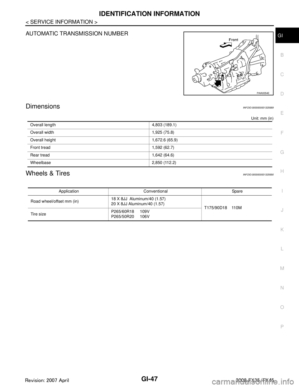
DimensionsINFOID:0000000001325689
Unit: mm (in)
Wheels & TiresINFOID:0000000001325690
PAIA0054E
Overall length 4,803 (189.1)
Overall width 1,925 (75.8)
Overall height 1,672.6 (65.9)
Front tread 1,592 (62.7)
Rear tread 1,642 (64.6)
Wheelbase 2,850 (112.2)
Application Conventional Spare
Road wheel/offset mm (in) 18 X 8JJ Aluminum/40 (1.57)
20 X 8JJ Aluminum/40 (1.57)
T175/90D18 110M
Tire size P265/60R18 109V
P265/50R20 106V
3AA93ABC3ACD3AC03ACA3AC03AC63AC53A913A773A893A873A873A8E3A773A983AC73AC93AC03AC3
3A893A873A873A8F3A773A9D3AAF3A8A3A8C3A863A9D3AAF3A8B3A8C
Page 3320 of 3924

GENERAL MAINTENANCEMA-3
< SERVICE INFORMATION >
C
DE
F
G H
I
J
K
M A
B
MA
N
O P
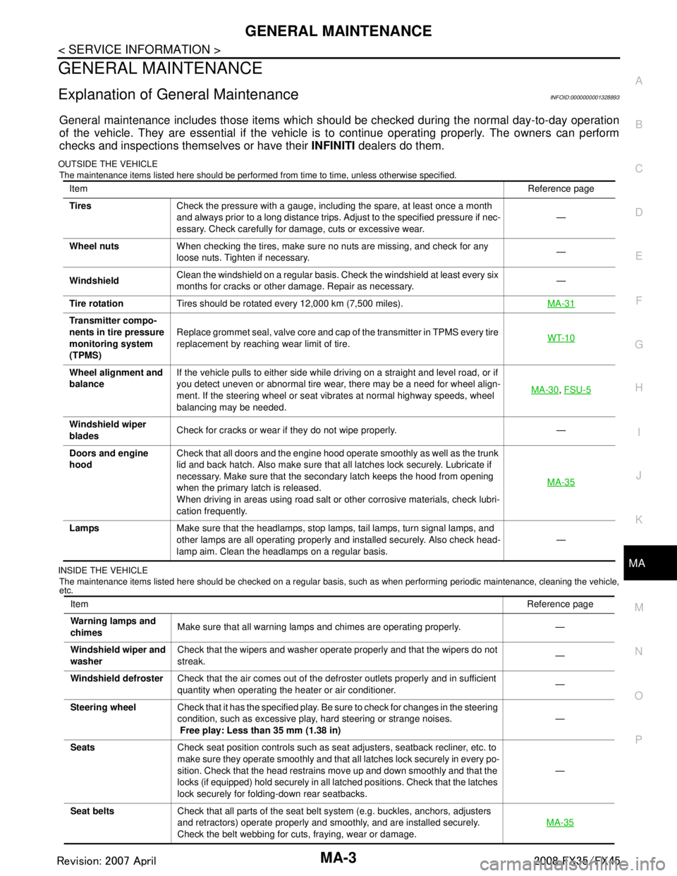
GENERAL MAINTENANCE
Explanation of Gene ral MaintenanceINFOID:0000000001328893
General maintenance includes those items which shoul d be checked during the normal day-to-day operation
of the vehicle. They are essential if the vehicle is to continue operating properly. The owners can perform
checks and inspections themselves or have their INFINITI dealers do them.
OUTSIDE THE VEHICLE
The maintenance items listed here should be performed from time to time, unless otherwise specified.
INSIDE THE VEHICLE The maintenance items listed here should be checked on a regular basis, such as when performing periodic maintenance, cleaning the vehicle,
etc.
Item Reference page
Tires Check the pressure with a gauge, including the spare, at least once a month
and always prior to a long distance trips. Adjust to the specified pressure if nec-
essary. Check carefully for damage, cuts or excessive wear. —
Wheel nuts When checking the tires, make sure no nuts are missing, and check for any
loose nuts. Tighten if necessary. —
Windshield Clean the windshield on a regular basis. Check the windshield at least every six
months for cracks or other damage. Repair as necessary. —
Tire rotation Tires should be rotated every 12,000 km (7,500 miles). MA-31
Transmitter compo-
nents in tire pressure
monitoring system
(TPMS)Replace grommet seal, valve core and cap of the transmitter in TPMS every tire
replacement by reaching wear limit of tire.
WT-10
Wheel alignment and
balanceIf the vehicle pulls to either side while driving on a straight and level road, or if
you detect uneven or abnormal tire wear, there may be a need for wheel align-
ment. If the steering wheel or seat vibrates at normal highway speeds, wheel
balancing may be needed. MA-30
,
FSU-5
Windshield wiper
blades Check for cracks or wear if they do not wipe properly. —
Doors and engine
hood Check that all doors and the engine hood operate smoothly as well as the trunk
lid and back hatch. Also make sure that all latches lock securely. Lubricate if
necessary. Make sure that the secondary latch keeps the hood from opening
when the primary latch is released.
When driving in areas using road salt or other corrosive materials, check lubri-
cation frequently. MA-35
Lamps
Make sure that the headlamps, stop lamps, tail lamps, turn signal lamps, and
other lamps are all operating properly and installed securely. Also check head-
lamp aim. Clean the headlamps on a regular basis. —
Item
Reference page
Warning lamps and
chimes Make sure that all warning lamps and chimes are operating properly. —
Windshield wiper and
washer Check that the wipers and washer operate properly and that the wipers do not
streak.
—
Windshield defroster Check that the air comes out of the defroster outlets properly and in sufficient
quantity when operating the heater or air conditioner. —
Steering wheel Check that it has the specified play. Be sure to check for changes in the steering
condition, such as excessive play, hard steering or strange noises.
Free play: Less than 35 mm (1.38 in) —
Seats Check seat position controls such as seat adjusters, seatback recliner, etc. to
make sure they operate smoothly and that all latches lock securely in every po-
sition. Check that the head restrains move up and down smoothly and that the
locks (if equipped) hold securely in all latched positions. Check that the latches
lock securely for folding-down rear seatbacks. —
Seat belts Check that all parts of the seat belt system (e.g. buckles, anchors, adjusters
and retractors) operate properly and smoothly, and are installed securely.
Check the belt webbing for cuts, fraying, wear or damage. MA-35
3AA93ABC3ACD3AC03ACA3AC03AC63AC53A913A773A893A873A873A8E3A773A983AC73AC93AC03AC3
3A893A873A873A8F3A773A9D3AAF3A8A3A8C3A863A9D3AAF3A8B3A8C