2008 INFINITI FX35 front wheel hub
[x] Cancel search: front wheel hubPage 1004 of 3924

BR-20
< SERVICE INFORMATION >
FRONT DISC BRAKE
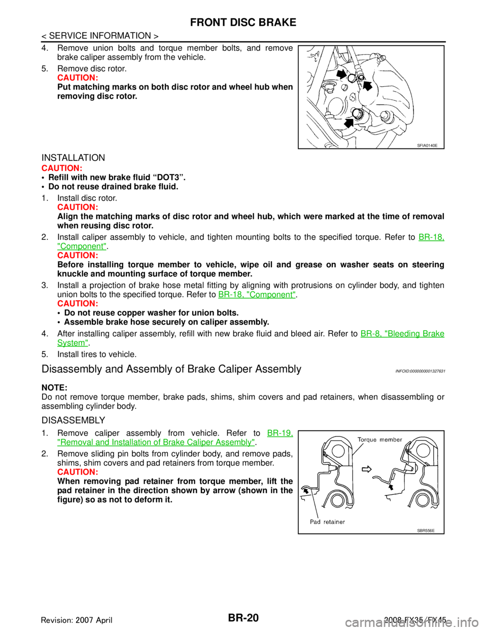
4. Remove union bolts and torque member bolts, and removebrake caliper assembly from the vehicle.
5. Remove disc rotor. CAUTION:
Put matching marks on both disc rotor and wheel hub when
removing disc rotor.
INSTALLATION
CAUTION:
Refill with new brake fluid “DOT3”.
Do not reuse drained brake fluid.
1. Install disc rotor.
CAUTION:
Align the matching marks of disc rotor and wheel hub, which were marked at the time of removal
when reusing disc rotor.
2. Install caliper assembly to vehicle, and tighten mounting bolts to the specified torque. Refer to BR-18,
"Component".
CAUTION:
Before installing torque member to vehicle, wipe oil and grease on washer seats on steering
knuckle and mounting surface of torque member.
3. Install a projection of brake hose metal fitting by aligning with protrusions on cylinder body, and tighten
union bolts to the specified torque. Refer to BR-18, "
Component".
CAUTION:
Do not reuse copper washer for union bolts.
Assemble brake hose securely on caliper assembly.
4. After installing caliper assembly, refill with new brake fluid and bleed air. Refer to BR-8, "
Bleeding Brake
System".
5. Install tires to vehicle.
Disassembly and Assembly of Brake Caliper AssemblyINFOID:0000000001327631
NOTE:
Do not remove torque member, brake pads, shims, shim covers and pad retainers, when disassembling or
assembling cylinder body.
DISASSEMBLY
1. Remove caliper assembly from vehicle. Refer to BR-19,
"Removal and Installation of Brake Caliper Assembly".
2. Remove sliding pin bolts from cylinder body, and remove pads, shims, shim covers and pad retainers from torque member.
CAUTION:
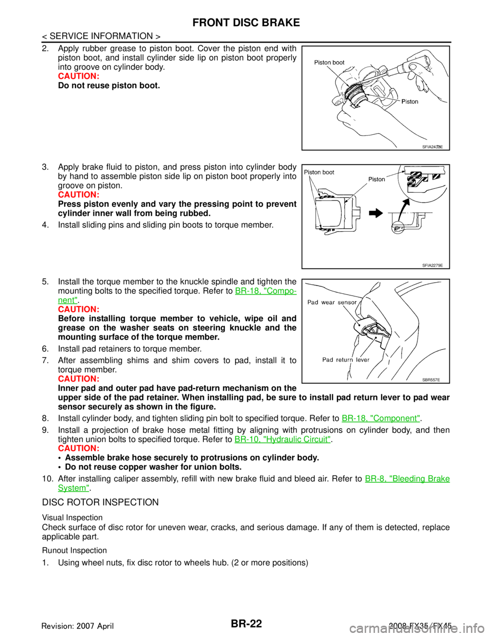
When removing pad retainer fr om torque member, lift the
pad retainer in the direction shown by arrow (shown in the
figure) so as not to deform it.
SFIA0140E
SBR556E
3AA93ABC3ACD3AC03ACA3AC03AC63AC53A913A773A893A873A873A8E3A773A983AC73AC93AC03AC3
3A893A873A873A8F3A773A9D3AAF3A8A3A8C3A863A9D3AAF3A8B3A8C
Page 1006 of 3924

BR-22
< SERVICE INFORMATION >
FRONT DISC BRAKE
2. Apply rubber grease to piston boot. Cover the piston end withpiston boot, and install cylinder side lip on piston boot properly
into groove on cylinder body.
CAUTION:
Do not reuse piston boot.
3. Apply brake fluid to piston, and press piston into cylinder body by hand to assemble piston side lip on piston boot properly into
groove on piston.
CAUTION:
Press piston evenly and vary the pressing point to prevent
cylinder inner wall from being rubbed.
4. Install sliding pins and sliding pin boots to torque member.
5. Install the torque member to the knuckle spindle and tighten the mounting bolts to the specified torque. Refer to BR-18, "
Compo-
nent".
CAUTION:
Before installing torque member to vehicle, wipe oil and
grease on the washer seats on steering knuckle and the
mounting surface of the torque member.
6. Install pad retainers to torque member.
7. After assembling shims and shim covers to pad, install it to torque member.
CAUTION:
Inner pad and outer pad have pad-return mechanism on the
upper side of the pad retainer. When installing pad, be sure to install pad return lever to pad wear
sensor securely as shown in the figure.
8. Install cylinder body, and tighten sliding pin bolt to specified torque. Refer to BR-18, "
Component".
9. Install a projection of brake hose metal fitting by aligning with protrusions on cylinder body, and then tighten union bolts to specified torque. Refer to BR-10, "
Hydraulic Circuit".
CAUTION:
Assemble brake hose securely to protrusions on cylinder body.
Do not reuse copper washer for union bolts.
10. After installing caliper assembly, refill with new brake fluid and bleed air. Refer to BR-8, "
Bleeding Brake
System".
DISC ROTOR INSPECTION
Visual Inspection
Check surface of disc rotor for uneven wear, cracks, and serious damage. If any of them is detected, replace
applicable part.
Runout Inspection
1. Using wheel nuts, fix disc rotor to wheels hub. (2 or more positions)
SFIA2432E
SFIA2279E
SBR557E
3AA93ABC3ACD3AC03ACA3AC03AC63AC53A913A773A893A873A873A8E3A773A983AC73AC93AC03AC3
3A893A873A873A8F3A773A9D3AAF3A8A3A8C3A863A9D3AAF3A8B3A8C
Page 1007 of 3924

FRONT DISC BRAKEBR-23
< SERVICE INFORMATION >
C
DE
G H
I
J
K L
M A
B
BR
N
O P
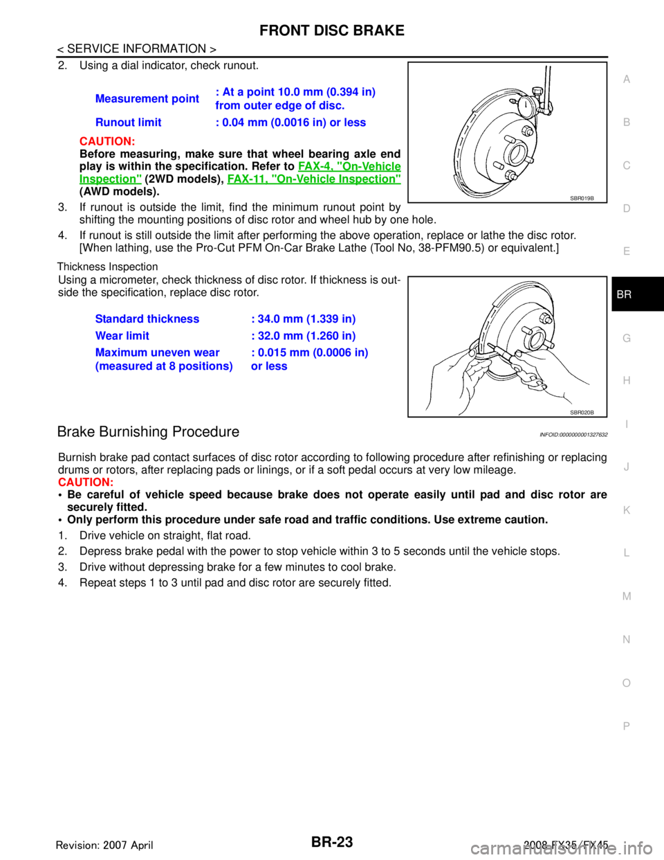
2. Using a dial indicator, check runout.
CAUTION:
Before measuring, make sure that wheel bearing axle end
play is within the sp ecification. Refer to FA X - 4 , "
On-Vehicle
Inspection" (2WD models), FA X - 11 , "On-Vehicle Inspection"
(AWD models).
3. If runout is outside the limit, find the minimum runout point by shifting the mounting positions of disc rotor and wheel hub by one hole.
4. If runout is still outside the limit after performing the above operation, replace or lathe the disc rotor.
[When lathing, use the Pro-Cut PFM On-Car Br ake Lathe (Tool No, 38-PFM90.5) or equivalent.]
Thickness Inspection
Using a micrometer, check thickness of disc rotor. If thickness is out-
side the specification, replace disc rotor.
Brake Burnishing ProcedureINFOID:0000000001327632
Burnish brake pad contact surfaces of disc rotor according to following procedure after refinishing or replacing
drums or rotors, after replacing pads or linings, or if a soft pedal occurs at very low mileage.
CAUTION:
Be careful of vehicle speed because brake does no t operate easily until pad and disc rotor are
securely fitted.
Only perform this procedure under safe road and traffic conditions. Use extreme caution.
1. Drive vehicle on straight, flat road.
2. Depress brake pedal with the power to stop vehicl e within 3 to 5 seconds until the vehicle stops.
3. Drive without depressing brake for a few minutes to cool brake.
4. Repeat steps 1 to 3 until pad and disc rotor are securely fitted. Measurement point
: At a point 10.0 mm (0.394 in)
from outer edge of disc.
Runout limit : 0.04 mm (0.0016 in) or less
SBR019B
Standard thickness : 34.0 mm (1.339 in)
Wear limit : 32.0 mm (1.260 in)
Maximum uneven wear
(measured at 8 positions) : 0.015 mm (0.0006 in)
or less
SBR020B
3AA93ABC3ACD3AC03ACA3AC03AC63AC53A913A773A893A873A873A8E3A773A983AC73AC93AC03AC3
3A893A873A873A8F3A773A9D3AAF3A8A3A8C3A863A9D3AAF3A8B3A8C
Page 1067 of 3924
![INFINITI FX35 2008 Service Manual
BRC-52
< SERVICE INFORMATION >[VDC/TCS/ABS]
WHEEL SENSORS
WHEEL SENSORS
Removal and InstallationINFOID:0000000001327698
REMOVAL
1. Disconnect wheel sensor connector.
2. Remove wheel sensor mounting b INFINITI FX35 2008 Service Manual
BRC-52
< SERVICE INFORMATION >[VDC/TCS/ABS]
WHEEL SENSORS
WHEEL SENSORS
Removal and InstallationINFOID:0000000001327698
REMOVAL
1. Disconnect wheel sensor connector.
2. Remove wheel sensor mounting b](/manual-img/42/57017/w960_57017-1066.png)
BRC-52
< SERVICE INFORMATION >[VDC/TCS/ABS]
WHEEL SENSORS
WHEEL SENSORS
Removal and InstallationINFOID:0000000001327698
REMOVAL
1. Disconnect wheel sensor connector.
2. Remove wheel sensor mounting bolts, grommets (front sensor) and clip.
3. Remove wheel sensor.
CAUTION:
Be careful of the followin
g when installing sensor.
As much as possible, avoid rotati ng sensor when removing it. Pull sensors out without pulling on
sensor harness.
Take care to avoid damaging sensor edges or roto r teeth. Remove wheel sensor first before remov-
ing front wheel hub and bearing assembly and rear fina l drive. This is to avoid damage to sensor wir-
ing and loss of sensor function.
INSTALLATION
Note the following, and install in the reverse order of removal.
CAUTION:
Be careful of the follow ing when installing sensor. Tighten in stallation bolts to specified torques.
When installing, make sure there is no foreign material such as iron chips on pick-up and mounting
hole of sensor. Make sure no foreign material h as been caught in the sensor rotor. Remove any for-
eign material and clean the mount.
When installing front sensor, be sure to press rubber grommets in until they lock at the three loca-
tions shown in the figure (2 at shock absorbers and 1 at body pa nel). When installed, harness must
not be twisted. White line on ha rness must be visible from front.
When installing rear sensor, attach harness at rear suspension member securely. Besides, harness
must not be twisted when installed.
PFIA0600E
3AA93ABC3ACD3AC03ACA3AC03AC63AC53A913A773A893A873A873A8E3A773A983AC73AC93AC03AC3
3A893A873A873A8F3A773A9D3AAF3A8A3A8C3A863A9D3AAF3A8B3A8C
Page 1068 of 3924
![INFINITI FX35 2008 Service Manual
SENSOR ROTORBRC-53
< SERVICE INFORMATION > [VDC/TCS/ABS]
C
D
E
G H
I
J
K L
M A
B
BRC
N
O P
SENSOR ROTOR
Removal and InstallationINFOID:0000000001327699
REMOVAL
Front
Sensor rotor cannot be disassembl INFINITI FX35 2008 Service Manual
SENSOR ROTORBRC-53
< SERVICE INFORMATION > [VDC/TCS/ABS]
C
D
E
G H
I
J
K L
M A
B
BRC
N
O P
SENSOR ROTOR
Removal and InstallationINFOID:0000000001327699
REMOVAL
Front
Sensor rotor cannot be disassembl](/manual-img/42/57017/w960_57017-1067.png)
SENSOR ROTORBRC-53
< SERVICE INFORMATION > [VDC/TCS/ABS]
C
D
E
G H
I
J
K L
M A
B
BRC
N
O P
SENSOR ROTOR
Removal and InstallationINFOID:0000000001327699
REMOVAL
Front
Sensor rotor cannot be disassembled. To replace sensor rotor, replace wheel hub and bearing assembly.
Refer to FAX-4, "
Removal and Installation"(2WD models), FAX-11, "Removal and Installation"(AWD models).
Rear
Follow procedure below to remove rear sensor rotor.
- Remove side flange. Refer to RFD-14, "
Removal and Installation".
- Using a bearing replacer and puller, remove sensor rotor from side flange.
INSTALLATION
Front
Sensor rotor cannot be disassembled. To replace sensor rotor, replace wheel hub and bearing assembly.
Refer to FAX-4, "
Removal and Installation"(2WD models), FAX-11, "Removal and Installation"(AWD models).
Rear
Follow procedure below to install rear sensor rotor.
- Using a drifts, press rear sensor rotor onto side flange.
- Install side flange. Refer to RFD-14, "
Removal and Installation".
Tool number A: ST30720000 (J-25405)
B: ST27863000 ( — )
C: KV40104710 ( — )
SFIA3387E
3AA93ABC3ACD3AC03ACA3AC03AC63AC53A913A773A893A873A873A8E3A773A983AC73AC93AC03AC3
3A893A873A873A8F3A773A9D3AAF3A8A3A8C3A863A9D3AAF3A8B3A8C
Page 2766 of 3924

FAX-1
DRIVELINE/AXLE
CEF
G H
I
J
K L
M
SECTION FA X
A
B
FA X
N
O P
CONTENTS
FRONT AXLE
2WD
SERVICE INFORMATION .. ..........................
2
PREPARATION .............................................. .....2
Special Service Tool ........................................... ......2
Commercial Service Tool ..........................................2
NOISE, VIBRATION AND HARSHNESS
(NVH) TROUBLESHOOTING .............................
3
NVH Troubleshooting Chart ................................ ......3
FRONT WHEEL HUB AND KNUCKLE ..............4
On-Vehicle Inspection ......................................... ......4
Removal and Installation ...........................................4
SERVICE DATA AND SPECIFICATIONS
(SDS) ...................................................................
6
Wheel Bearing ..................................................... ......6
AWD
SERVICE INFORMATION .. ..........................
7
PRECAUTIONS .............................................. .....7
Caution ................................................................ ......7
PREPARATION ..................................................8
Special Service Tool ............................................ .....8
Commercial Service Tool .........................................9
NOISE, VIBRATION AND HARSHNESS
(NVH) TROUBLESHOOTING ...........................
10
NVH Troubleshooting Chart ....................................10
FRONT WHEEL HUB AND KNUCKLE ............11
On-Vehicle Inspection ......................................... ....11
Removal and Installation .........................................11
FRONT DRIVE SHAFT .....................................13
On-Vehicle Inspection .............................................13
Removal and Installation (Left Side) ........................15
Removal and Installation (Right Side) .....................16
Disassembly and Assembly (Left Side) ...................18
Disassembly and Assembly (Right Side) .................21
SERVICE DATA AND SPECIFICATIONS
(SDS) .................................................................
26
Wheel Bearing .........................................................26
Drive Shaft ...............................................................26
3AA93ABC3ACD3AC03ACA3AC03AC63AC53A913A773A893A873A873A8E3A773A983AC73AC93AC03AC3
3A893A873A873A8F3A773A9D3AAF3A8A3A8C3A863A9D3AAF3A8B3A8C
Page 2769 of 3924
![INFINITI FX35 2008 Service Manual
FAX-4
< SERVICE INFORMATION >[2WD]
FRONT WHEEL HUB AND KNUCKLE
FRONT WHEEL HUB AND KNUCKLE
On-Vehicle InspectionINFOID:0000000001327506
Make sure the mounting conditions (looseness, back
lash) of ea INFINITI FX35 2008 Service Manual
FAX-4
< SERVICE INFORMATION >[2WD]
FRONT WHEEL HUB AND KNUCKLE
FRONT WHEEL HUB AND KNUCKLE
On-Vehicle InspectionINFOID:0000000001327506
Make sure the mounting conditions (looseness, back
lash) of ea](/manual-img/42/57017/w960_57017-2768.png)
FAX-4
< SERVICE INFORMATION >[2WD]
FRONT WHEEL HUB AND KNUCKLE
FRONT WHEEL HUB AND KNUCKLE
On-Vehicle InspectionINFOID:0000000001327506
Make sure the mounting conditions (looseness, back
lash) of each component and component status (wear,
damage) are normal.
WHEEL BEARING INSPECTION
Move wheel hub in the axial direction by hand. Che ck that there is no looseness of front wheel bearing.
Rotate wheel hub and make sure there is no unusual noi se or other irregular conditions. If there are any
irregular conditions, replace wheel hub and bearing assembly.
Removal and InstallationINFOID:0000000001327507
COMPONENTS
REMOVAL
1. Remove tires from vehicle with power tool.
2. Remove brake caliper with power tool. Hang it in a place where it will not interfere with work. Refer to BR-
18.
NOTE:
Avoid depressing brake pedal while brake caliper is removed.
3. Put alignment marks on disc rotor and wheel hub and bearing assembly, then remove disc rotor.
4. Remove wheel sensor from wheel hub and bearing assembly. Refer to BRC-52
.
CAUTION:
Do not pull on wheel sensor harness.
5. Remove cotter pin at steering outer socket, then loosen mount- ing nut.Axial end play : 0.05 mm (0.002 in) or less
1. Disc rotor 2. Wheel hub and bearing assembly 3. Splash guard
4. Steering knuckle 5. Cotter pin
Refer to
GI-8, "
Component", for the symbols in the figure.
PDIA1216E
SDIA1480E
3AA93ABC3ACD3AC03ACA3AC03AC63AC53A913A773A893A873A873A8E3A773A983AC73AC93AC03AC3
3A893A873A873A8F3A773A9D3AAF3A8A3A8C3A863A9D3AAF3A8B3A8C
Page 2770 of 3924
![INFINITI FX35 2008 Service Manual
FRONT WHEEL HUB AND KNUCKLEFAX-5
< SERVICE INFORMATION > [2WD]
C
EF
G H
I
J
K L
M A
B
FA X
N
O P
6. Use a ball joint remover (SST) to remove steering outer socket from steering knuckle. Be careful no INFINITI FX35 2008 Service Manual
FRONT WHEEL HUB AND KNUCKLEFAX-5
< SERVICE INFORMATION > [2WD]
C
EF
G H
I
J
K L
M A
B
FA X
N
O P
6. Use a ball joint remover (SST) to remove steering outer socket from steering knuckle. Be careful no](/manual-img/42/57017/w960_57017-2769.png)
FRONT WHEEL HUB AND KNUCKLEFAX-5
< SERVICE INFORMATION > [2WD]
C
EF
G H
I
J
K L
M A
B
FA X
N
O P
6. Use a ball joint remover (SST) to remove steering outer socket from steering knuckle. Be careful not to damage ball joint boot.
CAUTION:
Tighten temporarily mounting nut to prevent damage to
threads and to prevent ball jo int remover (SST) from com-
ing off.
7. Remove cotter pin at transve rse link, then loosen mounting nut.
8. Use a ball joint remover (SST) to remove transverse link from steering knuckle. Be careful not to damage ball joint boot.
CAUTION:
Tighten temporarily mounting nut to prevent damage to
threads and to prevent ball jo int remover (SST) from com-
ing off.
9. Remove fixing bolts and nuts between strut assembly and steer- ing knuckle with power tool.
10. Remove steering knuckle from vehicle.
11. Remove fixing bolts between steering knuckle and wheel hub and bearing assembly with power tool.
12. Remove splash guard and wheel hub and bearing assembly from steering knuckle.
INSPECTION AFTER REMOVAL
Check for deformity, cracks and damage on each parts, replace if necessary.
Ball Joint Inspection
Check for boot breakage, axial looseness, and torque of transverse link and steering outer socket ball joint.
Refer to FSU-13
, PS-17.
INSTALLATION
Refer to "Removal and Installation" for tightening torque. Install in the reverse order of removal.
NOTE:
Refer to component parts location and do not reuse non-reusable parts.
After removing/installing or replacing axle components, check wheel alignment. Refer to FSU-5, "
Wheel
Alignment Inspection".
After adjusting wheel alignment, adjust neutral position of steering angle sensor. Refer to BRC-8, "
Adjust-
ment of Steering Angle Sensor Neutral Position".
Check the following item after service
- Installation condition of wheel sensor harness
SDIA1434E
SDIA1435E
3AA93ABC3ACD3AC03ACA3AC03AC63AC53A913A773A893A873A873A8E3A773A983AC73AC93AC03AC3
3A893A873A873A8F3A773A9D3AAF3A8A3A8C3A863A9D3AAF3A8B3A8C