2008 GREAT WALL FLORID maintenance
[x] Cancel search: maintenancePage 144 of 281

Downloaded from www.Manualslib.com manuals search engine 137Steering System
Steering System Maintenance
Structure Introduction
The steering wheel has an airbag module which should only be inspected and repaired by a professional. The
steering column's upper section adopts a steel deformation and energy absorbing crumple structure which
ensures collision protection for the driver. The lower section uses a high precision sliding spline structure,
which can effectively eliminate structural interference caused by body deformation. The steering column angle
is adjustable, which can more easily adapt to the driver, and at the same time possesses reasonable reverse
efficiency to ensure the driver has a good feel for the road. Steering sys\
tem is as shown below:
Steering column assembly removal and
installation
1. Remove the airbag.
(a) Disconnect the battery's negative cable, and wait for
one minute before canceling the airbags function in
order to avoid unnecessary injury.
(b) To ensure steering column's proper installation, during
the entire removal process, the front tires must keep
straight.
(c) Remove the two hexagon screws and the airbag module.
Hexagon screw
Steering wheel
Steering column
Steering propeller shaft
PS fluid reservoir
Power steering pumpBelt
Power steering gearSteering combination pipe
Steering propeller shaft connector jacket assembly
Steering dust cover
Steering protection plate
Page 145 of 281
Downloaded from www.Manualslib.com manuals search engine GWFLORID Maintenance Manual138
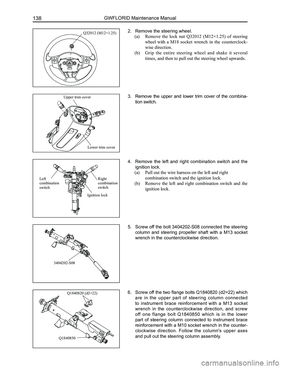
2. Remove the steering wheel.
(a) Remove the lock nut Q32012 (M12×1.25) of steering
wheel with a M18 socket wrench in the counterclock-
wise direction.
(b) Grip the entire steering wheel and shake it several
times, and then to pull out the steering wheel upwards.
3. Remove the upper and lower trim cover of the combina-
tion switch.
4. Remove the left and right combination switch and the
ignition lock.
(a) Pull out the wire harness on the left and right
combination switch and the ignition lock.
(b) Remove the left and right combination switch and the
ignition lock.
5. Screw off the bolt 3404202-S08 connected the steering
column and steering propeller shaft with a M13 socket
wrench in the counterclockwise direction.
6. Screw off the two flange bolts Q1840820 (d2=22) which
are in the upper part of steering column connected
to instrument brace reinforcement with a M13 socket
wrench in the counterclockwise direction, and screw
off one flange bolt Q1840850 which is in the lower
part of steering column connected to instrument brace
reinforcement with a M10 socket wrench in the counter-
clockwise direction. Follow the column's upper axes
and pull out the steering column assembly.
Q32012 (M12×1.25)
Lower trim cover
Upper trim cover
3404202-S08
Q1840820 (d2=22)
Q1840850
Right combination switch
Left combination switch
Ignition lock
Page 147 of 281
Downloaded from www.Manualslib.com manuals search engine GWFLORID Maintenance Manual140
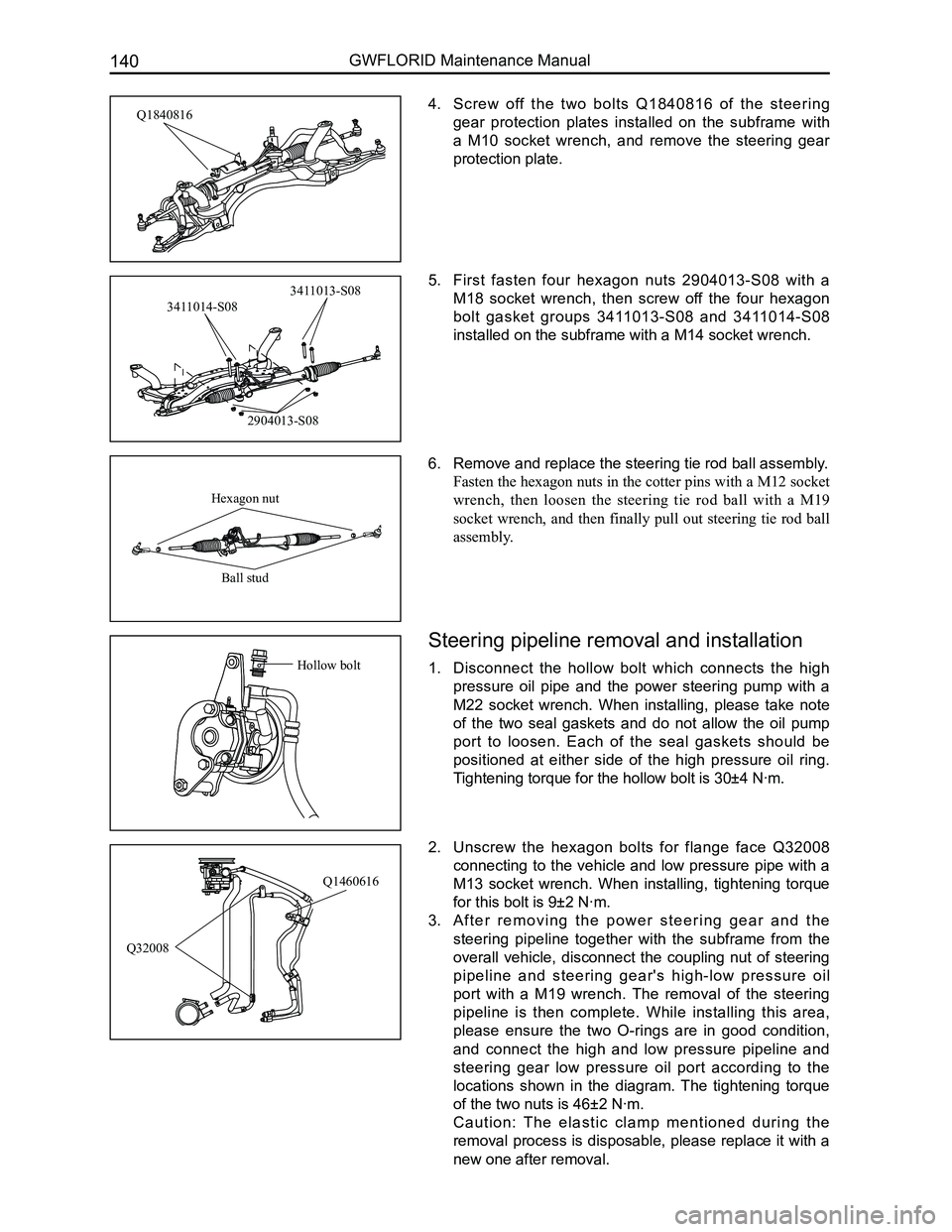
4. Screw off the two bolts Q1840816 of the steering
gear protection plates installed on the subframe with
a M10 socket wrench, and remove the steering gear
protection plate.
5. First fasten four hexagon nuts 2904013-S08 with a
M18 socket wrench, then screw off the four hexagon
bolt gasket groups 3411013-S08 and 3411014-S08
installed on the subframe with a M14 socket wrench.
6. Remove and replace the steering tie rod ball assembly.
Fasten the hexagon nuts in the cotter pins with a M12 socket
wrench, then loosen the steering tie rod ball with a M19
socket wrench, and then finally pull out steering tie rod ball
assembly.
2. Unscrew the hexagon bolts for flange face Q32008
connecting to the vehicle and low pressure pipe with a
M13 socket wrench. When installing, tightening torque
for this bolt is 9±2 N·m.
3. A f t e r r e m o v i n g t h e p o w e r s t e e r i n g g e a r a n d t h e
steering pipeline together with the subframe from the
overall vehicle, disconnect the coupling nut of steering
pipeline and steering gear's high-low pressure oil
port with a M19 wrench. The removal of the steering
pipeline is then complete. While installing this area,
please ensure the two O-rings are in good condition,
and connect the high and low pressure pipeline and
steering gear low pressure oil port according to the
locations shown in the diagram. The tightening torque
of the two nuts is 46±2 N·m.
C a u t i o n : T h e e l a s t i c c l a m p m e n t i o n e d d u r i n g t h e
removal process is disposable, please replace it with a
new one after removal.
Q1460616
Q32008
Q1840816
2904013-S08
3411014-S08
3411013-S08
Hexagon nut
Ball stud
Steering pipeline removal and installation
1. Disconnect the hollow bolt which connects the high
pressure oil pipe and the power steering pump with a
M22 socket wrench. When installing, please take note
of the two seal gaskets and do not allow the oil pump
port to loosen. Each of the seal gaskets should be
positioned at either side of the high pressure oil ring.
Tightening torque for the hollow bolt is 30±4 N·m.
Hollow bolt
Page 149 of 281

Downloaded from www.Manualslib.com manuals search engine GWFLORID Maintenance Manual142
Basic Information on the Electrical System ........................143
Fuse Box ........................................................................\
....144
Overall Vehicle’s Grounding Point Schematics ..................150
Key Electrical Component’s Module Schematics for
the Overall Vehicle..............................................................151
Wire Harness Distribution Chart for the Overall Vehicle .....152
Wire Harness Relationship and Plug-in Connections
Numbered Diagram ............................................................155
Wire Harness Plug-in Connectors and
Pin Function Diagram .........................................................156
Electrical Wiring Diagram for the Overall Vehicle ...............167
Vehicle Body Electrical System
Page 150 of 281
Downloaded from www.Manualslib.com manuals search engine 143Vehicle Body Electronic System
Basic Information on the Electrical System
Electrical system schematics reading instructions
1. Configuration introduction
The GWFLORID comes in three configurations: comfort, luxury and elite. The wire harness has two types of
configurations: One is a non jam protection comfort model, which is a combination of both comfort and luxury
type, the other type is called elite. These two configurations are universally used in most of this manual. The
parts that are only available for the non jam protection comfort type have been marked in this manual, please
pay attention to these sections while performing maintenance.
2. Fuse box and power supply introduction
The fuse box located inside the left side of the dashboard is No. 1 Fuse Box, the other one inside the left side of
the engine compartment is No. 2 Fuse Box.
• 30 represents a power cord for normal power, which is from the battery positive fuse box-60 A.
• 30a represents a power cord for normal power, which is from the battery positive fuse box-120 A.
• 30b represents a power cord for normal power, which is from the battery positive fuse box-120 A.
• 15 represents a power cord for small capacity electronics. When the ignition switch is at the "ON" position,
power is supplied by relay IG.
• 15a represents a power cord for small capacity electronics. When the ignition switch is at the "ON"
position, power is directly supplied by ignition switch IG1.
• 15b represents a power cord for small capacity electronics. When the ignition switch is at the "ON"
position, power is directly supplied by ignition switch IG2.
• X represents a power cord for small capacity electronics. When the ignition switch is at the "ACC"
position, power is supplied by relay ACC.
4. Wire's color and sectional area (mm2)
B-BlackW-WhiteR-RedBl-BlueBr-BrownY-Yellow
G-GreenP-PinkOr-OrangeV-VioletLg-Light greenGr-Gray
Mark the solid-colored wires with the letters in the above table. Double-colored wires' first letter is the primary
color, second letter is the secondary color.
For example:
Solid-colored wire: Red, marked as R.
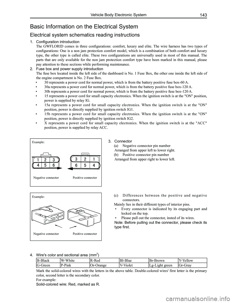
3. Connector
(a) Negative connector pin number
Arranged from upper left to lower right.
(b) Positive connector pin number
Arranged from upper right to lower left.
Example:
Example:
Negative connector
Negative connector
Positive connector
Positive connector
(c) D i f f e r e n c e s b e t w e e n t h e p o s i t i v e a n d n e g a t i v e
connectors.
Mainly lies in their different types of interior pins.
• Every connector is indicated by its engaging part and
locked on the top.
• Please pull out the connector, insted of its wires.
Note: Before pulling out the connector, please check its
type first.
Page 151 of 281
Downloaded from www.Manualslib.com manuals search engine GWFLORID Maintenance Manual144
Double-colored wire: Primary color is Red, secondary color is Blue, mark\
ed as RBl.
0.5BrGr means Brown wire with a Gray fine wire, and sectional area is 0.\
5 mm2.
Areas of importance in circuit maintenance
1. Before operating any electronic devices, and when tools or maintenance devices may easily make
contact with an uncovered electronic terminal, please make sure to turn the ignition switch to the LOCK
position, and then disconnect the battery's negative cable to avoid injury or vehicle damage. When the
ignition switch is on the ON position, please do not disconnect the battery's connecting wire or take out
the power's fuse, regardless if the engine is running or not.Otherwise it would seriously damage the
ECU and related microelectronic devices such as sensors.
2. When changing the fuse, please make sure that the new fuse possesses the proper current rating,
and is not above or below this rating.
3. When repairing the wire harnesses of the airbag and pretensioner, only specified contact points,
plugs, and wires are allowed to be used.
4. Before repairing the wire harness, make sure to eliminate any factor that might cause damage,
for example, the edge of a vehicle body part is too sharp, or the used electronics are damaged or
corroded.
5. Shielded wire should not be repaired, it must be replaced entirely once it is damaged.
6. Unless it is specified during the test, please do not use an analog multimeter to test the ECU and
sensor, instead use a high-impedance digital multimeter (internal resistance should be ≥10 kΩ) or a
vehicle multimeter for inspection.
7. When inspecting the connector with a digital multimeter, take the waterproof rubber cover off the
connector, and tightly insert the test pen along the connecting terminal. Don't use too much force, as
to avoid cracking the connector.
Circuit inspection steps
The principle of troubleshooting is to confirm the "possible cause". Once the possible cause is confirmed, the
components that need to be inspected are limited to the components that are related to the possible cause. The
confirmed possible cause should be based on theory and be supported by facts, but not just by intuition. If
one tries to solve the problem but does not adopt the proper troubleshooting steps, it may make the problem
worse. Then the possible cause not only can't be confirmed, but also maintenance can't be performed properly.
Troubleshooting should adhere to the four steps below:
1. Observe the symptoms carefully, inspect if there is anything else abnormal, and record it.
2. While confirming the possible causes, study the circuit diagram carefully, and regard it as a whole
system in order to understand the circuit. Thorough knowledge of switches, relays, and other
electronic components is obligatory for proper analysis.
3. Inspect and eliminate the problems one by one until the cause is found.
4. After the malfunction is fixed, make sure to check if the inspected system is working properly, and also
check if the maintenance may have caused any new problems.
Compres-
sor relay
Reserve
Sunroof (Elite) Lamplet
Reserve
Reserve
Reserve
Reserve Door and window Reserve Blower
Lamplet
relay Flasher relay Blower high
speed relay (Elite) Door and
window relay (Comfort, Luxury) Blower relay
Reserve
Front fog lamp
Combination
meter
Interior
lighting
central
door lock
brake lamp
CD player
Reserve
Reserve
Reserve
Cigarette
lighter
Rearview
mirror
Front wiper
Charge
Airbag
Reserve
Reverse lamp Rear fog lamp
Rear wiper
Defroster Compressor
ACC relay
IG relayRear wiper
relay Defroster
relay
Front fog
lamp relay Rear fog
lamp relay
Warning lamp
Turn signal lamp
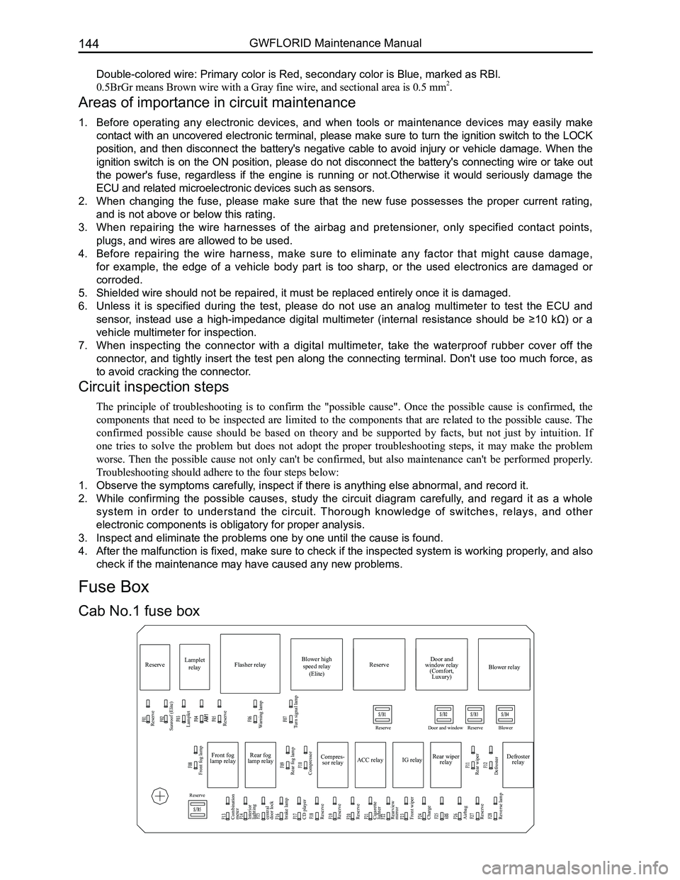
Cab No.1 fuse box
Fuse Box
Page 153 of 281

Downloaded from www.Manualslib.com manuals search engine GWFLORID Maintenance Manual146
Main relay
10A backup 15A backup 25A backup
Compressor relay
Reserve
Reserve
Fuel pump
Starter relay Main
relay High
beam Low
beam
Engine ECU
Fan relay High
Starter relay High beam relay Low beam relay Reserve
Horn Reserve Reserve Fan relay Low
Fan relay Low
Fan relay High
Horn relay
Engine compartment No.2 fuse box
Fuse number and bearer circuit
Fuse numberCurrent ratingFuse typePowerBearer circuit
F2930 A
AutoFuse
30 Battery (+)
Starter relay
F3025 AMain relay
F3115 AFuel pump relay
F3230 ASlow burn fuse Low speed fan relay
F33ReserveAutoFuse
F3430 ASlow burn fuse High speed fan relay
F3515 A
AutoFuse
High & low pitched horn
F3615 AHigh beam light relay
F3715 ALow beam light relay
F3810 AEngine ECU, diagnostic port
F3925 AABS ECU
F40Reserve
F4115 AAM2
F42Reserve
F43Backup 10 A
F44Backup 15 A
F45Backup 25 A
Page 155 of 281
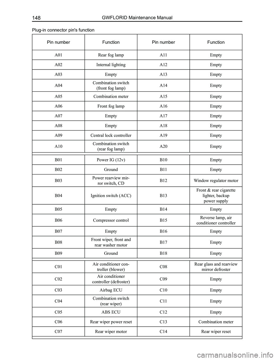
Downloaded from www.Manualslib.com manuals search engine GWFLORID Maintenance Manual148
Plug-in connector pin's function
Pin numberFunctionPin numberFunction
A01Rear fog lampA11Empty
A02Internal lightingA12Empty
A03EmptyA13Empty
A04Combination switch
(front fog lamp)A14Empty
A05Combination meter A15Empty
A06Front fog lampA16Empty
A07EmptyA17Empty
A08EmptyA18Empty
A09Central lock controllerA19Empty
A10Combination switch
(rear fog lamp)A20Empty
B01Power IG (12v)B10Empty
B02GroundB11Empty
B03Power rearview mir-
ror switch, CDB12Window regulator motor
B04Ignition switch (ACC)B13
Front & rear cigarette
lighter, backup
power supply
B05EmptyB14Empty
B06Compressor controlB15Reverse lamp, air
conditioner controller
B07EmptyB16Empty
B08Front wiper, front and
rear washer motorB17Empty
B09GroundB18Empty
C01Air conditioner con-
troller (blower) C08Rear glass and rearview
mirror defroster
C02Air conditioner
controller (defroster) C09Empty
C03Airbag ECU C10Empty
C04Combination switch
(rear wiper) C11Empty
C05ABS ECUC12Empty
C06Rear wiper power resetC13Combination meter
C07Rear wiper motorC14Rear wiper reset