Page 66 of 416
Chapter 6 Manual Transaxle AssemblySection 1 Frequent Problem DiagnosisComponent Viewfigure6-1Manual Transaxle Assembly Frequent Pr oblem Diagnosis3-25Battery support
Battery
fixing bar
Bottom board
Rear Engine
Vibration Absorber Starter assembly Engine hood
Control cable of
transmissionBattery
Harness of starter
Clamp
Clamp
Washer
Connector of
odometer sensor Clutch
Cylinder Starter Connector
Rear support of
engine
5 Spead Manual Transmission
(JL-S160/S160A)
Left front
drive shaftBall tie-rod
Cotter pin Hub nut Snap ring
Clamp
Left support of engineWasher
Washer Back-up lamp
ConnectorFilling plugDrain Plug Right front
drive shaft
assembly
Snap ring: Non-reusable parts -
Page 67 of 416

Table 6-1 Frequent problem diagnosisPossible causes
Transmission or the engine is suspended loosely or damaged;
Axial gap is improper;
Gear or bearing is worn or damaged;
Unsatisfactory transmission oil is used or oil level is low;
Engine idle is incorrect.
The oil seal or the O-ring is damaged.
The control cable is unqualified;
Synchronizer is poorly contacted with gear or worn;
Elasticity of the synchronous spring is insufficient;
Unqualified transmission oil is used.
Fork of the shift gear is worn or lifting spring is broken;
Gap between the synchronizer bush and the sleeve spline is too large;
Gear or bearing is worn or damaged. Sympton
Vibration and noise
Oil leakage of the transmission
Hard to shift
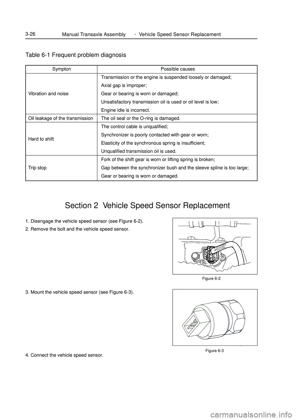
Trip stopManual Transaxle Assembly Vehicle Speed Sensor Replacement3-261. Disengage the vehicle speed sensor (see Figure 6-2).
2. Remove the bolt and the vehicle speed sensor.
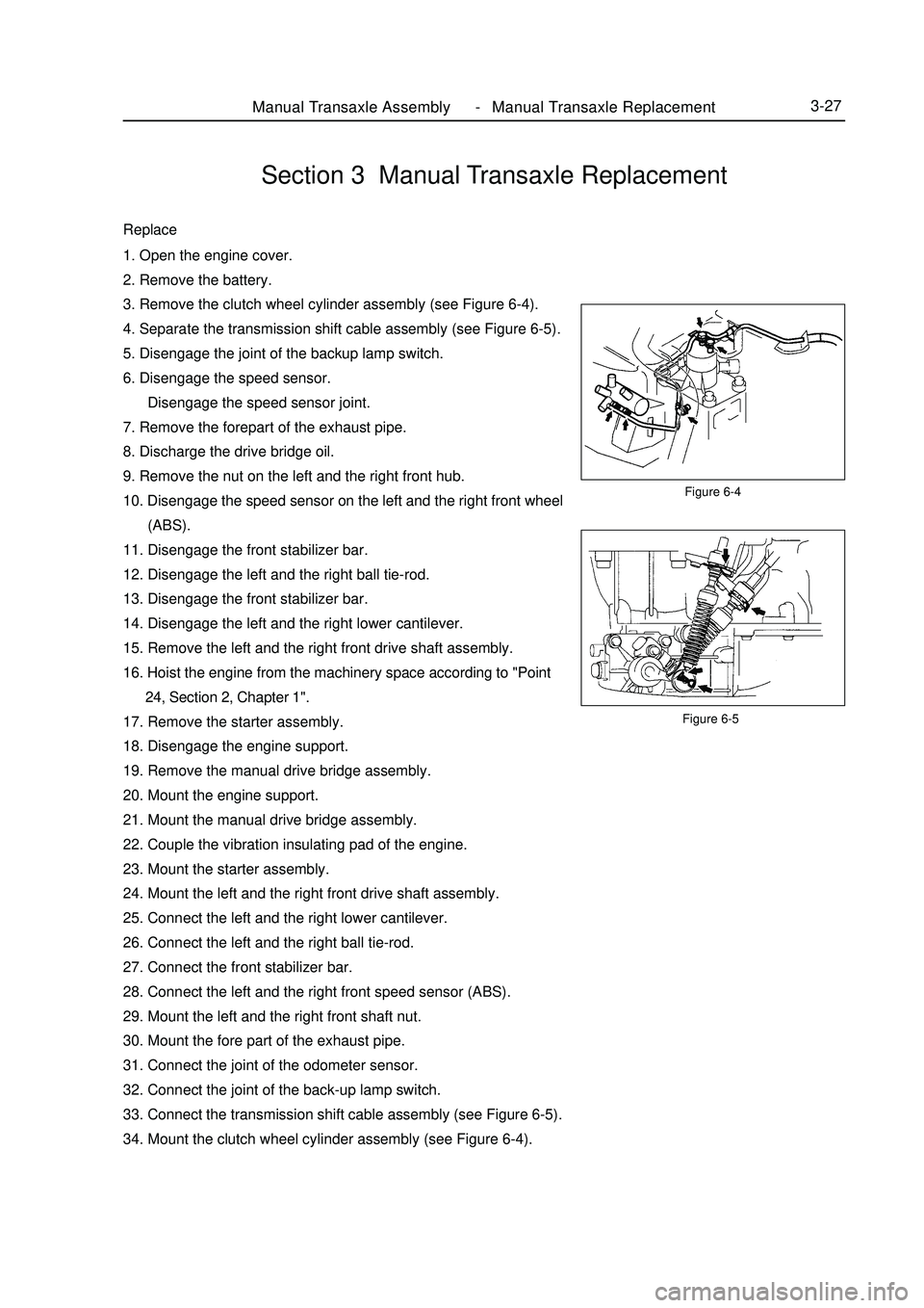
3. Mount the vehicle speed sensor (see Figure 6-3).
4. Connect the vehicle speed sensor.Section 2 Vehicle Speed Sensor ReplacementFigure 6-2
Figure 6-3 -
Page 68 of 416

Figure 6-5Manual Transaxle Assembly Manual Transaxle Replacement3-27Section 3 Manual Transaxle ReplacementReplace1. Open the engine cover.
2. Remove the battery.
3. Remove the clutch wheel cylinder assembly (see Figure 6-4).
4. Separate the transmission shift cable assembly (see Figure 6-5).
5. Disengage the joint of the backup lamp switch.
6. Disengage the speed sensor.
Disengage the speed sensor joint.
7. Remove the forepart of the exhaust pipe.
8. Discharge the drive bridge oil.
9. Remove the nut on the left and the right front hub.
10. Disengage the speed sensor on the left and the right front wheel
(ABS).
11. Disengage the front stabilizer bar.
12. Disengage the left and the right ball tie-rod.
13. Disengage the front stabilizer bar.
14. Disengage the left and the right lower cantilever.
15. Remove the left and the right front drive shaft assembly.
16. Hoist the engine from the machinery space according to "Point
24, Section 2, Chapter 1".
17. Remove the starter assembly.
18. Disengage the engine support.
19. Remove the manual drive bridge assembly.
20. Mount the engine support.
21. Mount the manual drive bridge assembly.
22. Couple the vibration insulating pad of the engine.
23. Mount the starter assembly.
24. Mount the left and the right front drive shaft assembly.
25. Connect the left and the right lower cantilever.
26. Connect the left and the right ball tie-rod.
27. Connect the front stabilizer bar.
28. Connect the left and the right front speed sensor (ABS).
29. Mount the left and the right front shaft nut.
30. Mount the fore part of the exhaust pipe.
31. Connect the joint of the odometer sensor.
32. Connect the joint of the back-up lamp switch.
33. Connect the transmission shift cable assembly (see Figure 6-5).
34. Mount the clutch wheel cylinder assembly (see Figure 6-4).Figure 6-4 -
Page 69 of 416
I. Replace the oil seal of transmission housing1. Remove the oil seal of the transmission housing (see Figure 6-6).
2. Mount the oil seal of the transmission housing (see Figure 6-7).
Attention:
Take care not to damage the lip surface of the oil seal.II. Replace the Oil Seal of the Drive Bridge Housing1. Remove the oil seal of the transaxle housing with special
maintenance tool (see Figure 6-8).
2. Mount the oil seal of the transaxle housing (see Figure 6-9).Section 4 Transmission/Transaxle Case Oil Seal ReplacementFigure 6-6
Figure 6-7Figure 6-8
Figure 6-9Manual Transaxle Assembly Transmission/Transaxle Case Oil Seal Replacement3-28 -
Page 72 of 416

Figure 7-3Automatic Transaxle Assembly Hydraulic Torque Converter and Transaxle3-31Figure 7-5 Figure 7-4Figure 7-1
Figure 7-23. Install transmission in the engine, its way like manual transmission. The torque converter cannot be allowed to
move in axial motion during operating (The dimension of A keeps constant). Install starter in the transmission
housing.
4. Connect Flexibility plate with torque converter, using 3 special bolts. The way is as follows. First, assemble one
bolt in the torque converter by the longer hole of the Flexibility plate, and then rotate engine belt pulley to install
the other bolts, finally use torque spanner to tighten the bolts. Tightening torque is 40~50N.m.
5. Install suspension bolt and drive shaft LH&RH, the assembling way like manual transmission.
6. Connect two cooling pipes as showed in the figure 7-3 with the corresponding pipe of transmission with clip.
7. Connect the cable between bracket of throttle and transmission actuator.
8. Throttle valve cable adjustment as follows:
First, use pliers to clip the hexangular position under throttle valve cable.Turn 60°~90°counterclockwise,
and lift throttle valve cable to make throttle valve cable adjustable move to top position, and then turn back
60°~90° clockwise, meanwhile, make it lock (See figure 7-4). Finally put accelerator pedal to end position.
When throttle valve makes "ka-ka" sound, the distance under the throttle valve should meet B=2~8mm. If not,
try again until the gap B=2~8mm under the throttle valve (see figure 7-5), if gap B=2-8mm, throttle valve cable
adjustment is finished.Central
plateFlexible plate
Torque converter
housing end
Torque
converterFront contact face
Torque converter
anchor point
Central anchor col-
umn -
Page 80 of 416

Section 2 Cable Type Transmission ControlReplacement1. Remove the upper cover in dashboard panel.
2. Remove the lower cover in dashboard panel.
3. Remove the cup-holder in the middle console.
4. Loosen transmission control cover.
5. Remove the handle of the gear shift lever.
6. Remove the middle console body.
7. Remove the control cables assembly of the transmission.
(1) Remove the two cotter pins and unfix the head of the control
cables of the transmission (see the right figure).
(2) Remove the control cables assembly after loosening the shift
bracket with bolts.
(3) Remove the two cotter pins and two washers, and then unfix
the two control cables from the manual transmission.
(4) Remove the two spring clips and unfix the two control cables
from the bracket.
(5) Remove the bolt and unfix the control cables.
(6) Remove the two bolts.
(7) Pull the control cables out of the body.
(8) Remove the retainer from the control cables.Transmission ControlCable Type Transmission Control4-3 -
Page 82 of 416
Section 3 Manual Transmission Shift MechanismReplacement1. Remove the upper cover in dashboard panel.
2. Remove the lower cover in dashboard panel.
3. Remove the cup-holder in the middle console.
4. Loosen transmission control cover.
5. Remove the handle of the gear shift lever.
6. Remove the middle console body.
7. Remove the control cables assembly of the transmission.
(1) Remove the two cotter pins and unfix the head of the control
cables of the transmission
(2) Remove the spring clips and separate the control cables from
the bracket.
8. Remove the four bolts and floor gear shift lever assembly.
9. Install the floor gear shift lever assembly.
Install the floor gear shift lever assembly with four bolts.
Torque: 12N.mTransmission ControlManual Transmission Shift Mechanism4-5 -
Page 83 of 416
Transmission ControlManual Transmission Shift Mechanism4-610. Connect the control cables assembly.
(1) Connect the control cables to floor gear shift lever assembly.
Note:
Make sure the spring clips engage firmly.
(2) Connect the ends of the control cables to the floor gear shift
lever assembly, and then install the cotter pins.
Note:
When connecting the ends, the dents shall be made upwards.
The cotter pins are inserted in a direction as shown in the figure.
(3) Connect the ends of the gear shift cables to the floor gear shift
lever assembly.
11. Install the middle console body.
12. Install the parking brake cover.
13. Install the handle of the gear shift lever.
14. Install the cup-holder.
15. Install the lower cover in dashboard panel.
16. Install the upper cover in dashboard panel.Sawcat part -