Page 39 of 419
Engine mechanism - Engine assemblyCO HC Trouble occurrence Possible causes 28 Normal HighUnstable idle speed
Low HighUnstable idle speed
(HC readings not stable)
High HighUnstable idle speed
(black smoke emission)1. Ignition system malfunctionIgnition timing incorrect Spark plug too dirty, short circuit or clearance
incorrect
2. Valve clearance incorrect
3. Air inlet and exhaust valve leaky
4. Cylinder leaky
1. Vacuum leak:PCV hoseIntake manifoldThrottle bodyIdle speed stepping motorVacuum booster and pipelines
2. Fire caused by too thin mixing ratio
1. Air filter core blocked
2. PCV valve blocked
3. EFI system malfunctionFuel pressure regulator malfunctionWater temperature sensor malfunctionIntake pressure sensor malfunctionECU malfunctionInjection nozzle malfunctionThrottle position sensor malfunction
Page 47 of 419

Engine mechanism - Engine assemblyEngine assemblyReplacement1. Take measures to prevent gasoline leaking.
2. Remove engine right bottom shield.
3. Remove engine left bottom shield.
4. Discharge coolant.
5. Remove front wheels.
6. Remove engine plastic hood components.
7. Remove battery.
8. Remove air filter assembly.
9. Remove air filter hose.
10. Remove battery tray.
11. Disassemble fuel hose assembly.
12. Remove throttle cable assembly.
13. Disassemble radiator hose inlet end.
14. Disassemble radiator hose outlet end.
15. Disassemble cold air pipe inlet hose.
16. Disassemble cold air pipe outlet hose.
17. Remove transmission control pull cable assembly.
18. Disassemble warm air water inlet hose [4G18-1300102].
19. Disassemble warm air water outlet hose [4G18-1300108].
20. Disassemble the hoses of all joints to connect vehicle body end.
21. Uncouple engine wire harness.(a) Remove glove compartment door.
(b) Remove engine wire harness from engine ECU and junction block.
(c) Pull out engine wire harness.
(b) Remove engine wire harness from junction block of engine room.
(e) Remove vehicle body earth wire. 36
Page 50 of 419

34. Remove power steering pump assembly.
35. Remove sub frame together with side member.(a) Remove front engine mounting assembly and rear en-
gine mounting assembly from engine assembly.
(b) Remove sub frame assembly.36. Remove starter mounting components
[4G18-3708100].
37. Remove transmission assembly.(a) Fix crankshaft with special tool, ant then remove 6 bolts.
(b) Remove transmission assembly.38. Remove clutch assembly [4G18-1601000]
and flywheel components [4G18-1005120J].(a) Fix crankshaft with special tool, ant remove clutch
assembly at first.
(b) Then remove flywheel components.39. Remove throttlesupporting plate [4G18-1008202].
40. Remove intake manifold assembly [4G18-
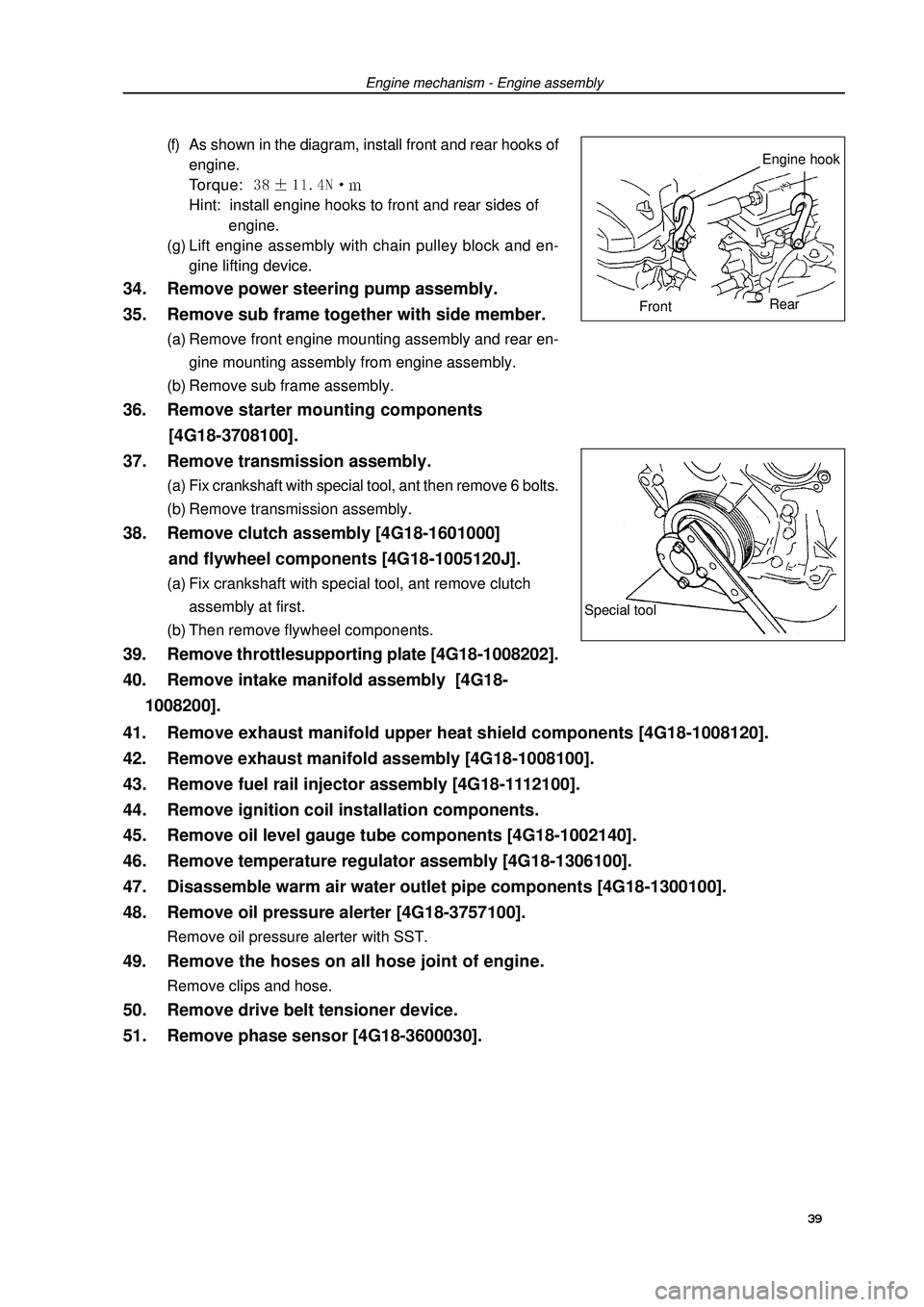
1008200].(f) As shown in the diagram, install front and rear hooks of
engine.
Torque: Hint: install engine hooks to front and rear sides of
engine.
(g) Lift engine assembly with chain pulley block and en-
gine lifting device.Engine mechanism - Engine assemblySpecial tool39 41. Remove exhaust manifold upper heat shield components [4G18-1008120].
42. Remove exhaust manifold assembly [4G18-1008100].
43. Remove fuel rail injector assembly [4G18-1112100].
44. Remove ignition coil installation components.
45. Remove oil level gauge tube components [4G18-1002140].
46. Remove temperature regulator assembly [4G18-1306100].
47. Disassemble warm air water outlet pipe components [4G18-1300100].
48. Remove oil pressure alerter [4G18-3757100].Remove oil pressure alerter with SST.49. Remove the hoses on all hose joint of engine.Remove clips and hose.50. Remove drive belt tensioner device.
51. Remove phase sensor [4G18-3600030].Engine hook
FrontRear
Page 52 of 419

Engine mechanism - Engine assembly64. Install temperature regulator assembly.(a) Check temperature regulator assembly o-ring.
(b) Install temperature regulator assembly as shown in the
diagram.
(c) Install engine water inlet pipe joint components.
Torque: 65. Install oil level gauge tube components.
66. Install ignition coil mounting components.Torque: m67. Install fuel rail injector assembly.(a) Install isolator on cylinder head.
(b) Install fuel rail injector assembly.
Torque: (c) Install fuel pipe retaining clip.68. Install exhaust manifold gasket and exhaust
manifold assembly.Torque: 69. Install exhaust manifold upper heat shield
components.Torque: 70. Install intake manifold assembly.Install new gasket and intake manifold assembly.
Torque: m71. Install throttle supporting plate.Torque: 72. Install flywheel components and clutch assembly.(a) Fix crankshaft with special tool.
(b) Clean bolts and bolt holes.
(c) Coat bolts with adhesive.
Adhesive: thread locking sealant 1234 (Kesaixin 1234).
(d) Install flywheel components.
As sequences shown in the diagram, tighten bolts at
several times.
Torque: 885Nm
(e) Install clutch assembly.Special
tool 41
Page 54 of 419

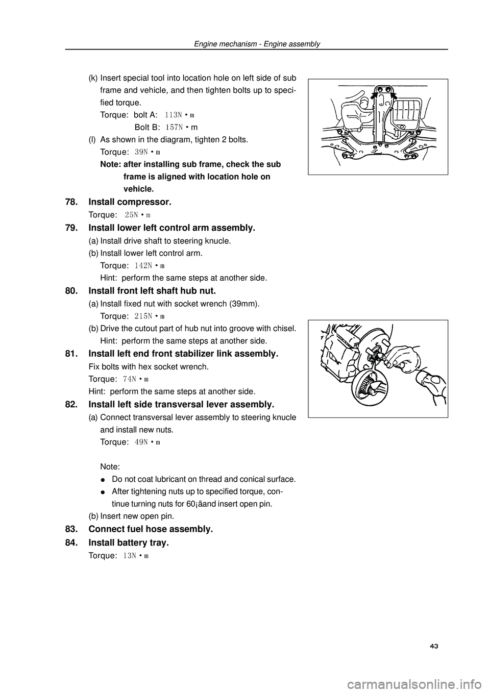
(k) Insert special tool into location hole on left side of sub
frame and vehicle, and then tighten bolts up to speci-
fied torque.
Torque: bolt A: Bolt B: m
(l) As shown in the diagram, tighten 2 bolts.
Torque: Note: after installing sub frame, check the sub
frame is aligned with location hole on
vehicle.78. Install compressor.Torque: 79. Install lower left control arm assembly.(a) Install drive shaft to steering knucle.
(b) Install lower left control arm.
Torque: Hint: perform the same steps at another side.80. Install front left shaft hub nut.(a) Install fixed nut with socket wrench (39mm).
Torque: (b) Drive the cutout part of hub nut into groove with chisel.
Hint: perform the same steps at another side.81. Install left end front stabilizer link assembly.Fix bolts with hex socket wrench.
Torque: Hint: perform the same steps at another side.82. Install left side transversal lever assembly.(a) Connect transversal lever assembly to steering knucle
and install new nuts.
Torque: Note:Do not coat lubricant on thread and conical surface.After tightening nuts up to specified torque, con-
tinue turning nuts for 60¡ãand insert open pin.
(b) Insert new open pin.83. Connect fuel hose assembly.
84. Install battery tray.Torque: Engine mechanism - Engine assembly 43
Page 56 of 419

Engine mechanism - Timing chain assemblyTiming chain assemblyReplacement1. Remove engine left bottom shield.
2. Remove engine right bottom shield.
3. Discharge coolant.
4. Remove engine plastic hood components.
5. Remove drive belt.
6. Remove power steering pump assembly.
7. Remove alternator assembly.
8. Uncouple engine wire harness.(a) Remove ignition coil joint, PS fuel pressure switch joint,
fuel line control joint and speed sensor joint.
(b) Remove bolts and nuts of fixed earth wire and put aside
engine wire harness.9. Remove ignition coil assembly.
10. Remove cylinder head cover components.(a) Remove fuel pipe retaining clip and 2 PCV hoses from
cylinder head cover.
(b) Remove 9 bolts, 2 seal washers, cylinder head cover
components and gasket.11. Remove right engine mounting assembly.(a) Remove PS oil pump reservoir and put it aside.
(b) Place wooden block between jack and engine, prop-
erly place the jack, and then remove right engine mount-
ing assembly.12. Turn crankshaft to cylinder 1 compression top
dead center position.
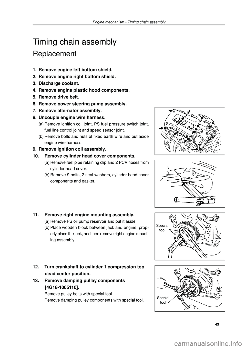
13. Remove damping pulley components
[4G18-1005110].Remove pulley bolts with special tool.
Remove damping pulley components with special tool.Special
tool
Special
tool45
Page 345 of 419

Panel/combination instrument--combination instrument
Panel / combination instrument
combination instrument
Trouble table
Lightening:
Phenomenon
All lights fail
Only one light failsPossible parts of trouble
1. combination instrument assembly
2. joint or harness
1. combination instrument assemblyReference pages
-
-
-
Indicator light:
Phenomenon
Trouble light fails
Charge light fails
Brake system light fails
ABS light fails
SRS lights fails
Door light fails
low fuel level light fails
low Oil pressure light failsPossible parts of trouble
1. harness or joint
2. engine ECU
3. combination instrument assembly
1. harness or joint
2. engine ECU
3. combination instrument assembly
1. harness or joint
2. ABS ECU
3. combination instrument assembly
1. harness or joint
2. ABS ECU
3. combination instrument assembly
1. harness or joint
2. airbag sensor assembly
3. combination instrument assembly
1. harness or joint
2. door control switch
3. combination instrument assembly
1. harness or joint
2. fuel level light switch
3. combination instrument assembly
1. combination instrument assembly
2. oil pressure light switch
3. harness or jointReference pages
-
-
-
-
-
-
-
-
335
-
-
335
-
-
-
-
-
-
-
335
335
-
335
335
� 334 �
Page 346 of 419

Panel/combination instrument--combination instrument
Indicator light:
Phenomenon
Turning light fails
Distant light failsPossible parts of trouble
1. harness or joint
2. turn light and safety warning light system
3. combination instrument assembly
1. harness or joint
2. left combination switch
3. combination instrument assemblyReference pages
-
-
335
-
-
335
Instrument:
Phenomenon
Revolution counter, petrol guage and
engine water thermometer fail
petrol guage fails or works abnormallyPossible parts of trouble
1. harness or joint
2. (panel) safety fuse
3. combination instrument assembly
1. harness or joint
2. Fuel guage sensor
3. combination instrument assemblyReference pages
-
-
335
-
335
335
Vehicle inspection
1. inspect speed counter
(1) Use speedometer tester to inspect allowed error of speedometer and action of speedometer
Reference: Km/h
speed indicated by speedometer actual speed
20km/h17-23km/h
40km/h35-40km/h
60km/h55-60km/h
80km/h75-80km/h
100km/h95-100km/h
120km/h 114-120km/h
140km/h133-140km/h
160km/h152-160km/h
Notes: tyre wear or tyre pressure too high or too low will increase error.
(2) Inspect speedometer needle offset
Reference: below 0.5km/h
� 335 �