Page 27 of 419

On-vehicle inspection1. Inspection of fuel pump function(a) Connect hand-held tester to diagnostic joint.
(b) Turn ignition switch to ON and turn main switch of hand-
held tester to ON.
Note: do not start the engine.
(c) Switch hand-held tester to function test state.
(d) For further details, please see hand-held tester operating
instruction.
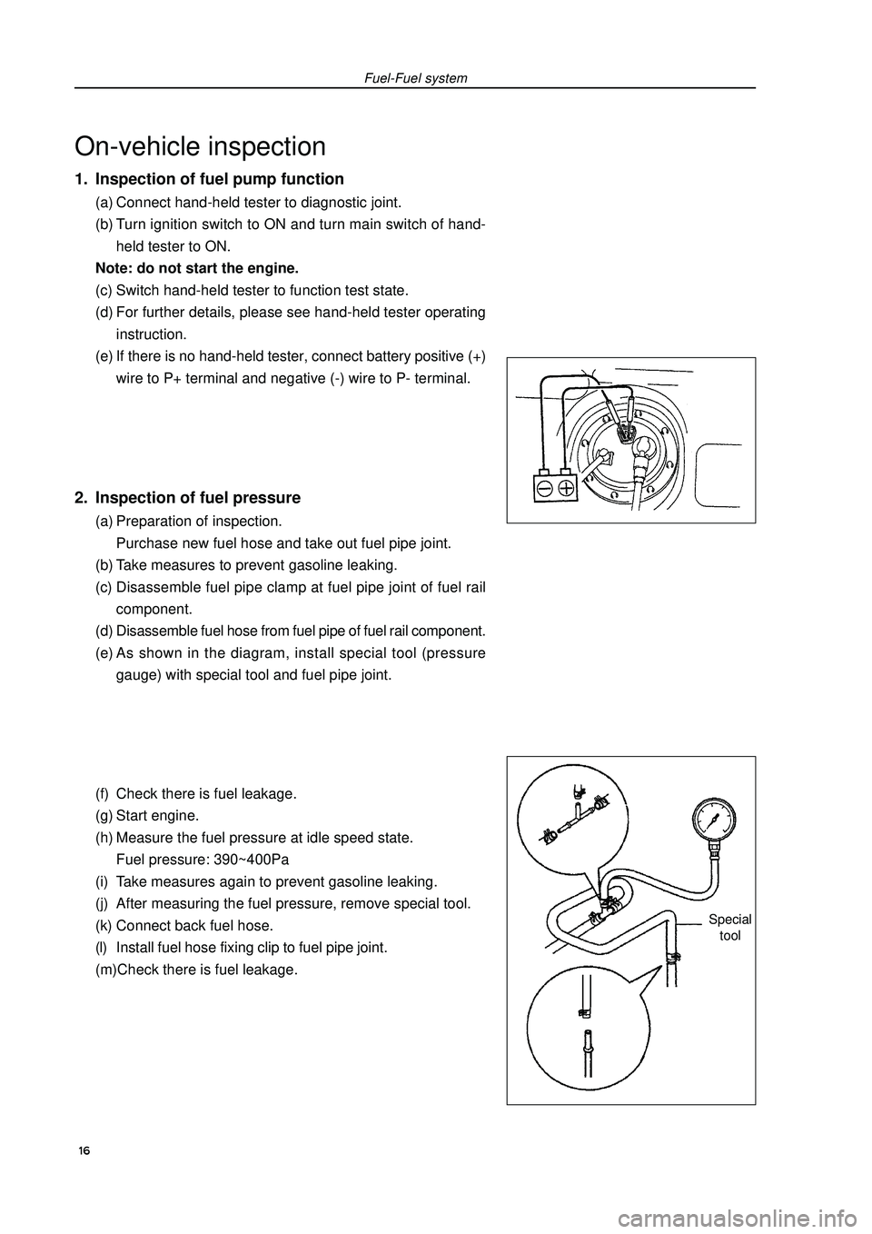
(e) If there is no hand-held tester, connect battery positive (+)
wire to P+ terminal and negative (-) wire to P- terminal.2. Inspection of fuel pressure(a) Preparation of inspection.
Purchase new fuel hose and take out fuel pipe joint.
(b) Take measures to prevent gasoline leaking.
(c) Disassemble fuel pipe clamp at fuel pipe joint of fuel rail
component.
(d) Disassemble fuel hose from fuel pipe of fuel rail component.
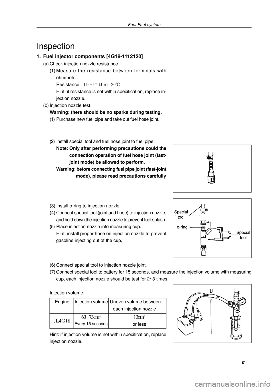
(e) As shown in the diagram, install special tool (pressure
gauge) with special tool and fuel pipe joint.
(f) Check there is fuel leakage.
(g) Start engine.
(h) Measure the fuel pressure at idle speed state.
Fuel pressure: 390~400Pa
(i) Take measures again to prevent gasoline leaking.
(j) After measuring the fuel pressure, remove special tool.
(k) Connect back fuel hose.
(l) Install fuel hose fixing clip to fuel pipe joint.
(m)Check there is fuel leakage.Fuel-Fuel systemSpecial
tool 16
Page 28 of 419

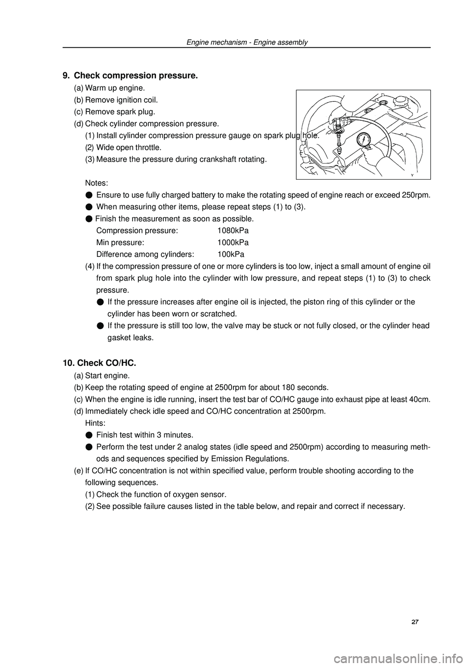
(6) Connect special tool to injection nozzle joint.
(7) Connect special tool to battery for 15 seconds, and measure the injection volume with measuring
cup, each injection nozzle should be test for 2~3 times.
Injection volume:Fuel-Fuel systemInspection1. Fuel injector components [4G18-1112120](a) Check injection nozzle resistance.
(1) Measure the resistance between terminals with
ohmmeter.
Resistance: Hint: if resistance is not within specification, replace in-
jection nozzle.
(b) Injection nozzle test.
Warning: there should be no sparks during testing.
(1) Purchase new fuel pipe and take out fuel hose joint.
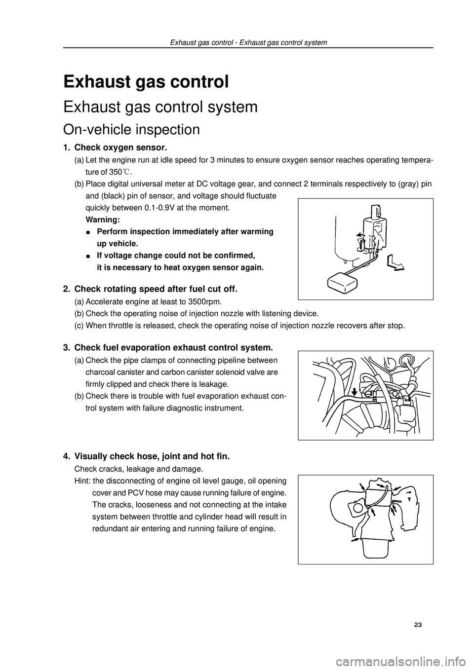
(2) Install special tool and fuel hose joint to fuel pipe.
Note: Only after performing precautions could the
connection operation of fuel hose joint (fast-
joint mode) be allowed to perform.
Warning: before connecting fuel pipe joint (fast-joint
mode), please read precautions carefully
(3) Install o-ring to injection nozzle.
(4) Connect special tool (joint and hose) to injection nozzle,
and hold down the injection nozzle to prevent fuel splash.
(5) Place injection nozzle into measuring cup.
Hint: install proper hose on injection nozzle to prevent
gasoline injecting out of the cup.
Engine Injection volume Uneven volume between
each injection nozzleEvery 15 secondsor lessHint: if injection volume is not within specification, replace
injection nozzle. 17 Special
toolSpecial
toolo-ring
Page 29 of 419
![GEELY FC 2008 Workshop Manual Fuel-Injection nozzle assemblyInjection nozzle assemblyReplacement1. Take measures to prevent gasoline leaking.
2. Remove engine plastic hood components.
3. Uncouple engine wire harness [4G18-3724100] GEELY FC 2008 Workshop Manual Fuel-Injection nozzle assemblyInjection nozzle assemblyReplacement1. Take measures to prevent gasoline leaking.
2. Remove engine plastic hood components.
3. Uncouple engine wire harness [4G18-3724100]](/manual-img/58/57161/w960_57161-28.png)
Fuel-Injection nozzle assemblyInjection nozzle assemblyReplacement1. Take measures to prevent gasoline leaking.
2. Remove engine plastic hood components.
3. Uncouple engine wire harness [4G18-3724100].(a) Remove injection nozzle joint.
(b) Remove exhaust gas hose.4. Remove fuel pipe assembly(a) Loosen oil feed hose clips.
(b) Pull oil feed hose away from fuse distribution pipe.
Notes:�zCheck there is dirt on fuel pipe and its joint before removing, and clean it off in the case of dirt.�zIt is only allowed to remove with hands.�zCheck there are foreign matters with the removed fuel pipe seal surface, and clean them off in the
case of foreign matters.�zCover the fuel pipe with plastic bag to avoid pipe damage and foreign matters entering.5. Remove fuel pipe assemblyRemove 2 bolts and oil feed pipe (together with injection nozzle).6. Remove injection nozzle components.Pull out 4 injection nozzles from oil feed pipe.7. Install injection nozzle components.Coat a thin layer of gasoline on o-ring and rotate left and right to push injection nozzle into oil feed pipe.
Notes:
�zBe careful not to rotate o-ring.
�zCheck injection nozzle could rotate smoothly after it is installed, and if not replace with new o-ring.8. Install fuel hose assembly.Install fuel hose to oil feed pipe.
Notes:
�zCheck there are damage or foreign matters in the binding site of fuel pipe.
�zAfter installing, pull the fuel pump with hands to check the fuel pipe is bound firmly with joint. 18
Page 34 of 419

Exhaust gas controlExhaust gas control systemOn-vehicle inspection1. Check oxygen sensor.(a) Let the engine run at idle speed for 3 minutes to ensure oxygen sensor reaches operating tempera-
ture of 350(b) Place digital universal meter at DC voltage gear, and connect 2 terminals respectively to (gray) pin
and (black) pin of sensor, and voltage should fluctuate
quickly between 0.1-0.9V at the moment.
Warning:Perform inspection immediately after warming
up vehicle.If voltage change could not be confirmed,
it is necessary to heat oxygen sensor again.Exhaust gas control - Exhaust gas control system2. Check rotating speed after fuel cut off.(a) Accelerate engine at least to 3500rpm.
(b) Check the operating noise of injection nozzle with listening device.
(c) When throttle is released, check the operating noise of injection nozzle recovers after stop.3. Check fuel evaporation exhaust control system.(a) Check the pipe clamps of connecting pipeline between
charcoal canister and carbon canister solenoid valve are
firmly clipped and check there is leakage.
(b) Check there is trouble with fuel evaporation exhaust con-
trol system with failure diagnostic instrument.4. Visually check hose, joint and hot fin.Check cracks, leakage and damage.
Hint: the disconnecting of engine oil level gauge, oil opening
cover and PCV hose may cause running failure of engine.
The cracks, looseness and not connecting at the intake
system between throttle and cylinder head will result in
redundant air entering and running failure of engine.23
Page 37 of 419
![GEELY FC 2008 Workshop Manual Engine mechanismEngine assemblyInspection1. Check coolant.
2. Check engine oil.
3. Check battery.
4. Check air filter assembly.
5. Check spark plug [4G18-3705113].
6. Check drive belt [4G18-1307107].H GEELY FC 2008 Workshop Manual Engine mechanismEngine assemblyInspection1. Check coolant.
2. Check engine oil.
3. Check battery.
4. Check air filter assembly.
5. Check spark plug [4G18-3705113].
6. Check drive belt [4G18-1307107].H](/manual-img/58/57161/w960_57161-36.png)
Engine mechanismEngine assemblyInspection1. Check coolant.
2. Check engine oil.
3. Check battery.
4. Check air filter assembly.
5. Check spark plug [4G18-3705113].
6. Check drive belt [4G18-1307107].Hint: do not check belt tension, because automatic tensioner is applied.7. Check ignition timing.(a) Warm up engine.
(b) Connect timing lamp to engine.
(c) Check ignition timing at idle speed.
Ignition timing: before top dead center Note: when checking ignition timing, place
transmission at neutral position.
Hint: After run the engine for 5 seconds with rotating
speed of 1000-1300rpm, check the engine could
recover to idle running.8. Check engine idle speed.(a) Warm up engine and run it at idle speed.
(b) Read engine rotating number in data flow with diagnostic instrument.
(c) Check idle speed.
Idle speed: about 750-850rpm
Notes:When checking idle speed, place cooling fan at OFF position.Turn off all auxiliary devices and air conditioner.Engine mechanism - Engine assemblyK-line 26
Page 38 of 419

9. Check compression pressure.(a) Warm up engine.
(b) Remove ignition coil.
(c) Remove spark plug.
(d) Check cylinder compression pressure.
(1) Install cylinder compression pressure gauge on spark plug hole.
(2) Wide open throttle.
(3) Measure the pressure during crankshaft rotating.
Notes:Ensure to use fully charged battery to make the rotating speed of engine reach or exceed 250rpm.When measuring other items, please repeat steps (1) to (3). Finish the measurement as soon as possible.
Compression pressure: 1080kPa
Min pressure: 1000kPa
Difference among cylinders: 100kPa
(4) If the compression pressure of one or more cylinders is too low, inject a small amount of engine oil
from spark plug hole into the cylinder with low pressure, and repeat steps (1) to (3) to check
pressure.If the pressure increases after engine oil is injected, the piston ring of this cylinder or the
cylinder has been worn or scratched.If the pressure is still too low, the valve may be stuck or not fully closed, or the cylinder head
gasket leaks.10. Check CO/HC.(a) Start engine.
(b) Keep the rotating speed of engine at 2500rpm for about 180 seconds.
(c) When the engine is idle running, insert the test bar of CO/HC gauge into exhaust pipe at least 40cm.
(d) Immediately check idle speed and CO/HC concentration at 2500rpm.
Hints:Finish test within 3 minutes.Perform the test under 2 analog states (idle speed and 2500rpm) according to measuring meth-
ods and sequences specified by Emission Regulations.
(e) If CO/HC concentration is not within specified value, perform trouble shooting according to the
following sequences.
(1) Check the function of oxygen sensor.
(2) See possible failure causes listed in the table below, and repair and correct if necessary.Engine mechanism - Engine assembly27
Page 39 of 419
Engine mechanism - Engine assemblyCO HC Trouble occurrence Possible causes 28 Normal HighUnstable idle speed
Low HighUnstable idle speed
(HC readings not stable)
High HighUnstable idle speed
(black smoke emission)1. Ignition system malfunctionIgnition timing incorrect Spark plug too dirty, short circuit or clearance
incorrect
2. Valve clearance incorrect
3. Air inlet and exhaust valve leaky
4. Cylinder leaky
1. Vacuum leak:PCV hoseIntake manifoldThrottle bodyIdle speed stepping motorVacuum booster and pipelines
2. Fire caused by too thin mixing ratio
1. Air filter core blocked
2. PCV valve blocked
3. EFI system malfunctionFuel pressure regulator malfunctionWater temperature sensor malfunctionIntake pressure sensor malfunctionECU malfunctionInjection nozzle malfunctionThrottle position sensor malfunction
Page 40 of 419
Engine mechanism - Drive beltDrive beltReplacement1. Remove engine right bottom shield.
2. Remove drive beltSlowly turn drive belt tensioner clockwise to loosen it.
Then remove drive belt and put back drive belt tensioner slowly
and gently.3. Install drive beltSlowly turn drive belt tensioner clockwise to loosen it.
Then install drive belt and put back drive belt tensioner slowly
and gently.29