Page 89 of 282

88
SAFETY
DEVICES
CORRECT USE
OF THE
VEHICLE
WARNING
LIGHTS AND
MESSAGES
IN AN
EMERGENCY
VEHICLE
MAINTENANCE
TECHNICAL
SPECIFICATIONS
INDEX
DASHBOARD
AND CONTROLS
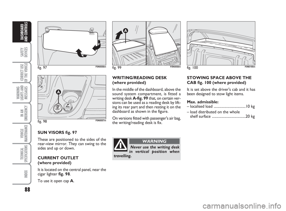
fig. 97F0N0056m
fig. 98F0N0057m
SUN VISORS fig. 97
These are positioned to the sides of the
rear-view mirror. They can swing to the
sides and up or down.
CURRENT OUTLET
(where provided)
It is located on the central panel, near the
cigar lighter fig. 98.
To use it open cap A.WRITING/READING DESK
(where provided)
In the middle of the dashboard, above the
sound system compartment, is fitted a
writing desk A-fig. 99that, on certain ver-
sions can be used as a reading desk by lift-
ing its rear part and then resting it on the
dashboard as shown in the figure.
On versions fitted with passenger's air bag,
the writing/reading desk is fix.STOWING SPACE ABOVE THE
CAB fig. 100 (where provided)
It is set above the driver's cab and it has
been designed to stow light items.
Max. admissible:
– localised load ...................................10 kg
– load distributed on the whole
shelf surface .....................................20 kg
fig. 99F0N0058mfig. 100F0N0190m
Never use the writing desk
in vertical position when
travelling.
WARNING
037-101 Ducato GB 6-11-2007 9:56 Pagina 88
Page 90 of 282

89
SAFETY
DEVICES
CORRECT USE
OF THE
VEHICLE
WARNING
LIGHTS AND
MESSAGES
IN AN
EMERGENCY
VEHICLE
MAINTENANCE
TECHNICAL
SPECIFICATIONS
INDEX
DASHBOARD
AND CONTROLS
fig. 102F0N0149m
FOLDING TOP (where provided)
To use it, pull tab A-fig. 102 and lower
the folding top.
It houses two recesses for glasses/cans and
tabletop with paper clip.
fig. 101F0N0191m
ODDMENT COMPARTMENT IN
THE CAB (CAPUCINE) fig. 101
(where provided)
This oddment compartment is set above
the sun visors and it has been designed to
offer prompt stowing for light items (e.g.
documents, road maps, etc. …)REARVIEW CAMERA AND
DISPLAY SYSTEM
(where provided)
The parking camera system fig. 103en-
ables the driver to see the area at the back
of the vehicle on the display A-fig. 104
set in the passenger compartment.
The system consists of a camera with a
plastic case installed on the rear cross
member on the roof that houses also the
third brake light, and a display with a plas-
tic case housed in the top oddment com-
partment.
fig. 103F0N0217m
037-101 Ducato GB 6-11-2007 9:56 Pagina 89
Page 91 of 282

90
SAFETY
DEVICES
CORRECT USE
OF THE
VEHICLE
WARNING
LIGHTS AND
MESSAGES
IN AN
EMERGENCY
VEHICLE
MAINTENANCE
TECHNICAL
SPECIFICATIONS
INDEX
DASHBOARD
AND CONTROLS
The display is provided with buttons
(On/Off, brightness, background bright-
ness). To use it, press the release button
and set the display to open position.
The rearview display is adjusted and ori-
ented like mirror and when it is not used
it shall be stowed into the top oddment
compartment.
ACTIVATION
The system activates with ignition key fit-
ted when engaging reverse or pressing the
relevant button. With reverse engaged
and vehicle moving, the system will work
up to a max. speed of about 15km/h and
it will deactivate if 18km/h speed is ex-
ceeded. Displayed image will stay on for
approx. 5 seconds after disengaging re-
verse. GENERAL DIRECTIONS
Visible range
The visible range varies according to ve-
hicle conditions (including full load con-
dition), vehicle characteristics and weath-
er conditions (daylight, rain, snow and fog);
with poor light or in full load conditions
the range of visibility may be reduced.
The camera covers a range of approx. 3
m length and approx. 5.5 m max. width
fig. 105.Instructions for use
To clean the camera use a soft cloth when
the protecting glass is dirty or frozen (out-
side). Never use other tools for cleaning
it to prevent scratching the glass.
To clean the display use also a dry soft
cloth. Dust can be removed using proper
brushes provided for the purpose. Nev-
er use detergents.
The display glass may break if blown. In
this event do not touch the leaking fluid.
Rinse immediately with water and soap in
case of accidental contact.
fig. 104F0N0214mfig. 105F0N0215m
037-101 Ducato GB 6-11-2007 9:56 Pagina 90
Page 92 of 282

91
SAFETY
DEVICES
CORRECT USE
OF THE
VEHICLE
WARNING
LIGHTS AND
MESSAGES
IN AN
EMERGENCY
VEHICLE
MAINTENANCE
TECHNICAL
SPECIFICATIONS
INDEX
DASHBOARD
AND CONTROLS
MULTIMETER
See the booklet provided by the multi-
meter Manufacturer for more detailed in-
formation on operation and use.
Multimeter installation is compulsory if the
vehicle weight (with or without the trail-
er) exceeds 3.5 tons.
IMPORTANT Changes to the instrument
or to the signal transmission system which
effects the instrument recordings, espe-
cially for fraudulent purposes, may be a
criminal offence.
IMPORTANT When a macrograph is fit-
ted and the vehicle has been parked for
longer than 5 days, it is advisable to dis-
connect the battery negative terminal to
preserve the charge status. USER INTERFACE
Display user interface consists of the fol-
lowing fig. 106:
❒Brightness adjustment: 2 buttons
❒Background brightness adjustment: 2
buttons
❒ON/OFF button: to display camera
images although reverse is not engaged
To go back to initial configuration, keep
the ON/OFF button pressed for about 3
seconds with system off. In this event the
ON/OFF button will flash twice to con-
firm the operation.TEXT MESSAGES ON THE
DISPLAY
Text messages will be displayed in the fol-
lowing conditions:
❒5 seconds after engaging reverse a
warning message will be displayed.
❒When exceeding 18 km/h speed and
only the activation button is ON, the
camera image will disappear and a
message indicating system stand-by
will be displayed for about 5 seconds.
❒When exceeding 18 km/h speed and
reverse is engaged, the camera image
will disappear and a warning message
will be displayed until speed slows
down to 15 km/h. In this case camera
image is displayed again.
The system enables to change the language
of the display messages. To set the re-
quired language, with system off: press at
the same time the ON/OFF button and
any other button, then select the required
language scrolling the menu using the
ON/OFF button. After selecting the re-
quired language, wait for approx. 3 sec-
onds to store it.
fig. 106F0N0216m
037-101 Ducato GB 6-11-2007 9:56 Pagina 91
Page 93 of 282

92
SAFETY
DEVICES
CORRECT USE
OF THE
VEHICLE
WARNING
LIGHTS AND
MESSAGES
IN AN
EMERGENCY
VEHICLE
MAINTENANCE
TECHNICAL
SPECIFICATIONS
INDEX
DASHBOARD
AND CONTROLS
IMPORTANT
Do not use abrasive detergents or sol-
vents to clean the device. To clean its ex-
ternal surface, use a wet cloth or special
products for cleaning synthetic materials.
The multimeter is installed and sealed with
lead by authorised personnel: access to
the device and relevant power and record-
ing cables is forbidden.
The vehicle owner is responsible for gov-
erning the instrument use. The inspection
must be carried out at least every two
years and will include a test to confirm
correct operation.
After the inspection, check that the plate
is updated with specified data.DOORS
CENTRAL DOOR
LOCKING/UNLOCKING SYSTEM
Locking from the outside
With the doors closed, press the button
Øon the remote control fig. 107or fit
and turn clockwise the metal insert into
the driver’s door lock.
Door locking is only possible if all the
doors are closed. Opening one or more
doors by pressing the button
Øon the re-
mote control fig. 107, will make the di-
rection indicators and the button led A-
fig. 110flash quickly for about 3 seconds.
With this function active, buttons Aand
B fig. 110are disabled.
fig. 107F0N0060m
Pressing twice briefly the button Øon the
remote control fig. 107will engage the
dead lock device (see paragraph “Dead
lock device”).
Door unlocking from the outside
Briefly press button
Æfig. 107or Ëfig.
108, according to versions, to obtain re-
mote door unlocking, timed ceiling light
turning on, directions indicator double
fig. 108F0N0145m
037-101 Ducato GB 6-11-2007 9:56 Pagina 92
Page 94 of 282

93
SAFETY
DEVICES
CORRECT USE
OF THE
VEHICLE
WARNING
LIGHTS AND
MESSAGES
IN AN
EMERGENCY
VEHICLE
MAINTENANCE
TECHNICAL
SPECIFICATIONS
INDEX
DASHBOARD
AND CONTROLS
flashing. Turn the metal insert counter-
clockwise into the driver’s door lock fig.
109to unlock all the doors.
Door locking/unlocking from
the inside
Press button A-fig. 110to lock and press
button Bto unlock the doors. Block/re-
lease actions are carried out centrally
(front and rear). When doors are locked
the button led Ais on and pressing the
button Bwill obtain central unlocking of
the doors and turning off of the led. When
doors are unlocked, the button led is off
and pressing the button will obtain central
locking of the doors. Door locking is ac-
tivated only if all the doors are perfectly
closed.
fig. 109F0N0059mfig. 110F0N0047m
fig. 111F0N0132m
Pulling the internal door handle of one of the
rear doors will unlock the relevant door.
Lacking power (blown fuse, battery discon-
nected, etc.) it is however possible to lock
the doors manually.
After exceeding 20 km/h speed, doors will
be locked automatically if the set up menu
function has been selected (see paragraph
“Multifunction display” in this section).
LOAD COMPARTMENT KEY
fig. 111
Lock activation is indicated by the led on
the key.
The led turns on in the following cases:
❒after each door lock command gener-
ated by the key itself or by key Øon
the dashboard;
❒upon instrument panel activation;
❒upon opening one of the front doors;
❒when the doors are locked at 20 km/h
(if this is activated from the menu);
Deactivation takes place upon opening
one of the load compartment doors or
upon a door release request (load com-
partment or centralised) or upon a release
request via the remote control/door pawl. After locking doors by:
❒remote control;
❒door revolving plug;
it will not be possible to unlock the doors
by pressing button
A-fig. 110.
IMPORTANT With central locking active
pulling the opening lever of one of the front
doors will cause central locking deactivation.
037-101 Ducato GB 6-11-2007 9:56 Pagina 93
Page 95 of 282

94
SAFETY
DEVICES
CORRECT USE
OF THE
VEHICLE
WARNING
LIGHTS AND
MESSAGES
IN AN
EMERGENCY
VEHICLE
MAINTENANCE
TECHNICAL
SPECIFICATIONS
INDEX
DASHBOARD
AND CONTROLS
DEAD LOCK DEVICE
(where provided)
This safety device enables to inhibit:
❒door internal handles;
❒locking/unlocking buttons A-B fig. 110;
thus hindering doors opening from inside
the passenger’s compartment in case of at-
tempt to break-into (e.g.: window breaking).
The dead lock device guarantees the best
protection against unwanted access.
Therefore, it should be actuated every
time the vehicle is parked and left unat-
tended.
Once the dead lock device
has been actuated, doors
cannot be opened from the passen-
ger’s compartment in any way what-
soever. For this reason, make sure
there are no person left inside the ve-
hicle. If the battery of the key with
remote control is down, the dead lock
device can be deactivated only by fit-
ting the metal insert of the key in
both front door revolving plugs as de-
scribed previously: in this case the
dead lock device will stay engaged
only on the rear doors.
WARNINGDevice activation
The dead lock device is automatically ac-
tivated on every door when pressing twice
briefly the remote control button
Ø, fig.
107.
Device activation is indicated by 3 flashing
of direction indicators and flashing of the
button led A-fig. 110.
If one of the doors is not perfectly closed,
the dead lock device will not activate, thus
preventing that a person getting into the ve-
hicle from the open door remains blocked
inside the passenger’s compartment when
she/he closes the door.
Device deactivation
The device is deactivated automatically on
every door in the following cases:
❒when opening the driver’s door using
the key without remote control;
❒when unlocking doors using the re-
mote control;
❒turning the ignition key to MAR.
037-101 Ducato GB 6-11-2007 9:56 Pagina 94
Page 96 of 282

95
SAFETY
DEVICES
CORRECT USE
OF THE
VEHICLE
WARNING
LIGHTS AND
MESSAGES
IN AN
EMERGENCY
VEHICLE
MAINTENANCE
TECHNICAL
SPECIFICATIONS
INDEX
DASHBOARD
AND CONTROLS
SIDE SLIDING DOORTo open the side sliding door, raise the
handle Aand guide the door.
The side sliding door is equipped with a
lock that stops it at the end of its open-
ing run. Operate the outer handle A(or
the corresponding inner one) and push the
door to close it.
In any case, always make sure that the
door is correctly fastened in the door
open catch.
SLIDING SIDE WINDOW
(where provided) fig. 112a
To open, press the two handles Btoward
one another and slide the glass.
When the two opening handles are re-
leased, the sliding glass may stop in inter-
mediate positions.MOBILE FOOT BOARD fig. 113
(where provided)
When opening the passenger’s compart-
ment side door or the load compartment
door, a foot board will come out under
the vehicle floor to make easier to get in-
to the vehicle.
fig. 112F0N0061m
When leaving the vehicle
parked with the sliding doors
open, always check that the door
hooks are properly fastened into the
retaining device.
WARNING
Do not move the vehicle
with side doors open.
WARNING
Always make sure the foot
board is fully retracted be-
fore moving off. Since the foot board
is interlocked with the side sliding
door, if the foot board is not fully re-
tracted or rear doors are not perfectly
closed will cause instrument panel
warning light
´turning on.
WARNING
fig. 113F0N0176mfig. 112aF0N0240m
037-101 Ducato GB 6-11-2007 9:56 Pagina 95