Page 370 of 554

WARNING!
It is the driver 's responsibility to change to the max
load inflation pressure (cold) low pressure warning
threshold condition when not driving in the light
load condition as defined as two occupants ( 150 lbs
each) plus 200 pounds of cargo. The vehicle ªLight
Load Definitionº is found in the Supplemental Tire
Pressure Information label located on the rear face of
the driver door. Failure to do so may cause you to lose
control resulting in an accident, causing serious or
fatal injury.
To switch back to the max load inflation pressure (cold)
low pressure warning threshold, press the ªLight Loadº
reset switch. It is not necessary to first fill the tires to the
max load inflation pressure (cold) values to switch the
TPMS system to the max load inflation pressure (cold)low pressure warning threshold. If after pressing the
ªLight Loadº reset switch and tire pressures are below
the max load inflation pressure (cold) low pressure
warning thresholds, the TPMS low pressure warning
telltale lamp located in the Instrument Cluster will turn
ON and a chime will sound. The tire pressures are now
required to be inflated to the max load inflation pressure
(cold) values described on the Tire and Loading Informa-
tion label. The Tire and Loading Information label is
located on the drivers side B-pillar. If the ªLight Loadº
reset switch LED turns OFF the TPMS has been reset and
the TPMS is using the max load inflation pressure (cold)
low pressure warning thresholds.
Tire Pressure Monitor System Components
The Tire Pressure Monitor System (TPMS) uses wireless
technology with wheel rim mounted electronic sensors to
monitor tire pressure levels. Sensors, mounted to each
wheel as part of the valve stem, transmit tire pressure
readings to the Receiver Module.
368 STARTING AND OPERATING
Page 371 of 554

NOTE:It is particularly important, for you to check the
tire pressure in all of your tires regularly and to maintain
the proper pressure.
The Tire Pressure Monitoring System (TPMS) consists of
the following components:
²Receiver Module
²4 Wheel Sensors
²2 Trigger Modules (mounted in the front wheel-wells)
²ªLight Loadº Reset Switch (located in the instrument
panel)
²Tire Pressure Monitoring Telltale Lamp
Tire Pressure Monitoring Low Pressure Warnings
The Tire Pressure Monitoring Telltale Lamp will
illuminate in the instrument cluster, and an au-
dible chime will be activated when one or more of
the four active road tire pressures are low. Should this
occur, you should stop as soon as possible, check the
inflation pressure of each tire on your vehicle and inflate
each tire to the vehicle's recommended cold placard
pressure value. The system will automatically update
and the Tire Pressure Monitoring Lamp will extinguish
once the updated tire pressures have been received. The
vehicle may need to be driven for up to 10 minutes above
15 mph (25 km/h) to receive this information.
Check TPMS Warnings
The Tire Pressure Monitoring Telltale Warning Light
located in the Instrument Cluster will flash on and off for
75 seconds and will remain on solid when a system fault
is detected. The system fault will also sound a chime. If
STARTING AND OPERATING 369
5
Page 372 of 554

the ignition key is cycled, this sequence will repeat,
providing the system fault still exists. A system fault can
occur by any of the following scenarios:
1. Signal interference due to electronic devices or driving
next to facilities emitting the same Radio Frequencies as
the TPM sensors.
2. Installing aftermarket window tinting that affects ra-
dio wave signals.
3. Accumulation of snow or ice around the wheels or
wheel housings.
4. Using tire chains on the vehicle.
5. Using wheels/tires not equipped with TPM sensors.
6. Loss of communication with the trigger modules or
tire pressure monitoring sensors.
NOTE: Your vehicle is equipped with a non-matching
full size spare wheel and tire assembly.1. This spare tire does not have a tire pressure monitor-
ing sensor. Therefore, the TPMS will not monitor the tire
pressure in the spare tire.
2. If you install the full size spare tire in place of a road
tire that has a pressure below the low-pressure warning
limit, upon the next ignition key cycle, a chime will
sound and the TPM Telltale Light will still turn ON due
to the low tire.
3. However, after driving the vehicle for up to 10 min-
utes above 15 mph (25 km/h), the TPM Telltale Light will
flash on and off for 75 seconds and then remain on solid.
4. For each subsequent ignition key cycle, a chime will
sound and the TPM Telltale Light will flash on and off for
75 seconds and then remain on solid.
5. Once you repair or replace the original road tire, and
reinstall it on the vehicle in place of the full size spare tire,
the TPMS will update automatically and the TPM Telltale
370 STARTING AND OPERATING
Page 384 of 554
Gross Axle Weight Rating (GAWR)
The GAWR is the maximum permissible load on the front
and rear axles. The load must be distributed in the cargo
area so that the GAWR of each axle is not exceeded.
Each axle GAWR is determined by the components in the
system with the lowest load carrying capacity (axle,
springs, tires or wheels). Heavier axles or suspension
components sometimes specified by purchasers for in-
creased durability does not necessarily increase the vehi-
cle's GVWR.
Tire Size
The tire size on the Label represents the actual tire size on
your vehicle. Replacement tires must be equal to the load
capacity of this tire size.
Rim Size
This is the rim size that is appropriate for the tire size
listed.
Inflation Pressure
This is the cold tire inflation pressure for your vehicle for
all loading conditions up to full GAWR.
Curb Weight
The curb weight of a vehicle is defined as the total weight
of the vehicle with all fluids, including vehicle fuel, at full
capacity conditions, and with no occupants or cargo
loaded into the vehicle. The front and rear curb weight
values are determined by weighing your vehicle on a
commercial scale before any occupants or cargo are
added.
382 STARTING AND OPERATING
Page 391 of 554
Fifth-Wheel Hitch
A special high platform with a coupling that mounts over
the rear axle of the tow vehicle in the truck bed. Connects
a vehicle and fifth-wheel trailer with a coupling king pin.
Gooseneck Hitch
The gooseneck hitch employs a pivoted coupling arm
which attaches to a ball mounted in the bed of a pickup
truck. The coupling arm connects to the hitch mounted
over the rear axle in the truck bed.
Trailer Hitch Classification
The rear bumper is intended to tow trailers up to 2,000
lbs (907 kg) without added equipment or alterations to
the standard equipment. Your vehicle may be factory
equipped for safe towing of trailers weighing over 2,000
lbs (907 kg) with the optional Trailer Tow Prep Package.
See your dealer for package content.
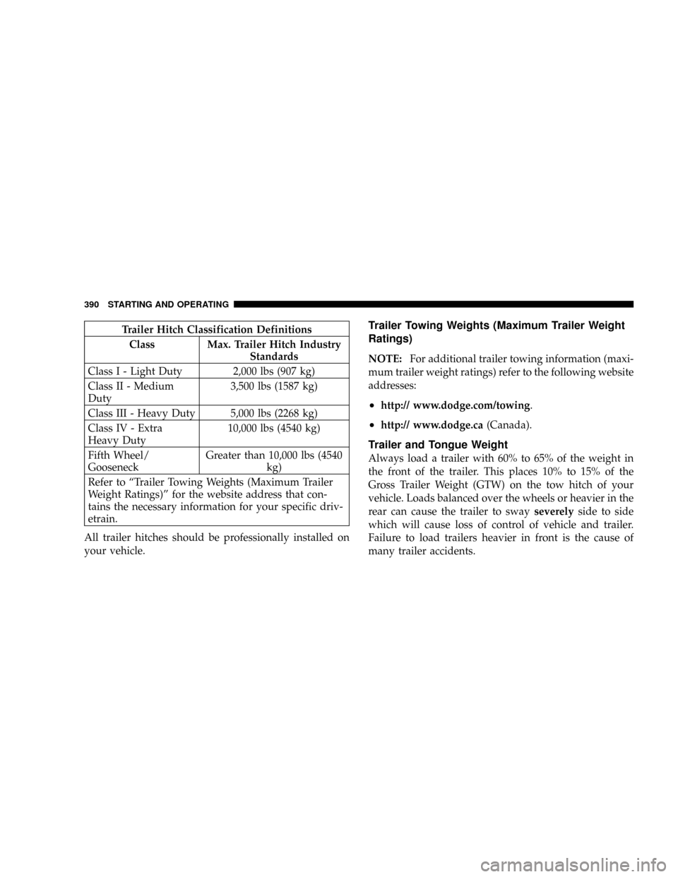
The following chart provides the industry standard for
the maximum trailer weight a given trailer hitch class can
tow and should be used to assist you in selecting the
correct trailer hitch for your intended towing condition.
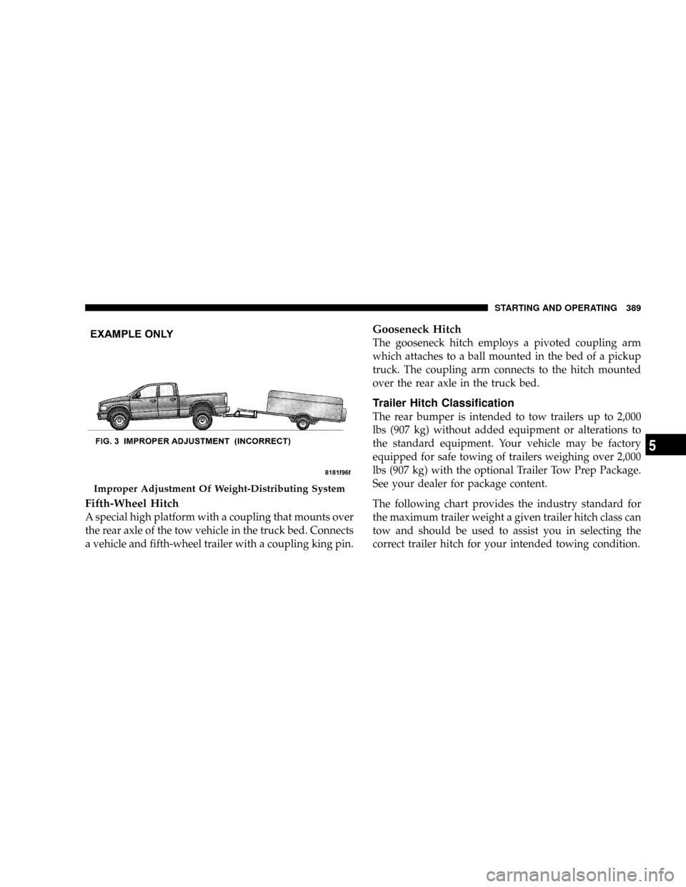
Improper Adjustment Of Weight-Distributing System
STARTING AND OPERATING 389
5
Page 392 of 554
Trailer Hitch Classification Definitions
Class Max. Trailer Hitch Industry
Standards
Class I - Light Duty 2,000 lbs (907 kg)
Class II - Medium
Duty3,500 lbs (1587 kg)
Class III - Heavy Duty 5,000 lbs (2268 kg)
Class IV - Extra
Heavy Duty10,000 lbs (4540 kg)
Fifth Wheel/
GooseneckGreater than 10,000 lbs (4540
kg)
Refer to ªTrailer Towing Weights (Maximum Trailer
Weight Ratings)º for the website address that con-
tains the necessary information for your specific driv-
etrain.
All trailer hitches should be professionally installed on
your vehicle.Trailer Towing Weights (Maximum Trailer Weight
Ratings)
NOTE:For additional trailer towing information (maxi-
mum trailer weight ratings) refer to the following website
addresses:
²http:// www.dodge.com/towing.
²http:// www.dodge.ca(Canada).
Trailer and Tongue Weight
Always load a trailer with 60% to 65% of the weight in
the front of the trailer. This places 10% to 15% of the
Gross Trailer Weight (GTW) on the tow hitch of your
vehicle. Loads balanced over the wheels or heavier in the
rear can cause the trailer to swayseverelyside to side
which will cause loss of control of vehicle and trailer.
Failure to load trailers heavier in front is the cause of
many trailer accidents.
390 STARTING AND OPERATING
Page 395 of 554
loss of control, poor performance or damage to brakes,
axle, engine, transmission, steering, suspension, chas-
sis structure or tires.
²Safety chains must always be used between your
vehicle and trailer. Always connect the chains to the
frame or hook retainers of the vehicle hitch. Cross the
chains under the trailer tongue and allow enough
slack for turning corners.
²Vehicles with trailers should not be parked on a grade.
When parking, apply the parking brake on the tow
vehicle. Put the tow vehicle automatic transmission in
P for Park. With a manual transmission, shift the
transmission into reverse. And with four-wheel-drive
vehicles, make sure the transfer case is not in neutral.
Always, block or9chock9the trailer wheels.
²GCWR must not be exceeded.
²Total weight must be distributed between the tow
vehicle and the trailer such that the following four
ratings are not exceeded:
1. GVWR
2. GTW
3. GAWR
4. Tongue weight rating for the trailer hitch utilized
(This requirement may limit the ability to always
achieve the 10% to 15% range of tongue weight as a
percentage of total trailer weight).
STARTING AND OPERATING 393
5
Page 405 of 554
Before Plowing
²
Check the hydraulic system for leaks and proper fluid
level.
²Check the mounting bolts and nuts for proper tightness.
²Check the runners and cutting edge for excessive wear.
The cutting edge should be 1/4 to 1/2 inch (6.4 mm
to13 mm) above ground in snow plowing position.
²Check that snowplow lighting is connected and func-
tioning properly.
Snowplow Model Prep Package Availability
For Detailed Information Visit www.dodge.com or refer
to the Current Dodge Truck Body Builders Guide.
1. The 1500 models are NOT available for snowplow
applications.
2. The maximum number of occupants in the truck
should not exceed two.3. The total GVWR, or the Front GAWR, or the Rear
GAWR should never be exceeded.
4. The snowplow prep packages are not available with
the Sport Package.
5. Cargo capacity will be reduced by the addition of
options or passengers, etc.
The loaded vehicle weight, including the snowplow sys-
tem, all aftermarket accessories, driver, passengers, op-
tions, and cargo, must not exceed either the Gross Vehicle
Weight (GVWR) or Gross Axle Weight (GAWR) ratings.
These weights are specified on the Safety Compliance
Certification Label on the driver's side door opening.
NOTE: Detach the snowplow when transporting
passengers.
Vehicle front end wheel alignment was set to specifications
at the factory without consideration for the weight of the
plow. Front end tow-in should be checked and reset if
STARTING AND OPERATING 403
5