2008 DODGE RAM 3500 GAS four wheel drive
[x] Cancel search: four wheel drivePage 275 of 554
STARTING AND OPERATING
CONTENTS
mStarting Procedures ± Gas Engines...........278
NNormal Starting......................278
NAutomatic Transmission ± If Equipped......279
NManual Transmission ± If Equipped........279
NIf Engine Fails To Start.................280
NAfter Starting........................281
mEngine Block Heater Ð If Equipped.........282
mAutomatic Transmission..................282
NAutomatic Transmission With Overdrive.....283mManual Transmission....................288
NShifting Ð 2500/3500 Models.............289
NShifting Ð 1500 Vehicles................291
NDownshifting ± All Manual Transmissions....292
NReverse Shifting......................293
mFour-Wheel Drive Operation Ð If Equipped....294
NManually Shifted Transfer Case Operating
Information/Precautions................294
NShifting Procedure - Manually Shifted Transfer
Case..............................297
5
Page 296 of 554
The ªknock-overº prevents the driver from accidentally
entering the REVERSE (R) shift area and warns the driver
that they are about to shift the transmission into RE-
VERSE (R). Due to this feature, a slow shift to REVERSE
(R) can be perceived as a high shift effort.
On 2500/3500 models, when shifting out of reverse bring
the vehicle to a complete stop and depress the clutch.
Shifting out of reverse prior to a complete stop may cause
high shift effort.
FOUR-WHEEL DRIVE OPERATION Ð IF
EQUIPPED
Four-wheel drive trucks are equipped with either a
manually shifted transfer case or an electronically shifted
transfer case. Refer to the operating instructions for your
transfer case, located in this section.
Manually Shifted Transfer Case Operating
Information/Precautions
The transfer case provides 4 mode positions-2(rear)-
wheel drive high range, 4-wheel drive high range, neu-
tral, and 4-wheel drive low range.
This transfer case is intended to be driven in the 2-wheel
drive position (2H) for normal street and highway con-
ditions such as dry, hard surfaced roads.
When additional traction is required, the transfer case 4H
and 4L positions can be used to lock the front and rear
driveshafts together and force the front and rear wheels
to rotate at the same speed. This is accomplished by
simply moving the shift lever to the desired positions.
The 4H and 4L positions are intended for loose, slippery
road surfaces only. Driving in the 4H and 4L positions on
dry, hard surfaced roads may cause increased tire wear
and damage to the driveline components.
294 STARTING AND OPERATING
Page 297 of 554

The 4-wheel drive light (4WD), located in the instrument
cluster, alerts the driver that the vehicle is in 4-wheel
drive and that the front and rear driveshafts are locked
together. This light illuminates when the transfer case is
shifted to either the 4H or 4L positions. There is no light
for the 2H or NEUTRAL positions.
When operating your vehicle in 4L, the engine speed is
approximately three times that of the 2H or 4H positions
at a given road speed. Take care not to overspeed the
engine and do not exceed 25 mph (40 km/h).
Proper operation of 4-wheel drive vehicles depends on
tires of equal size, type and circumference on each wheel.
Any difference will adversely affect shifting and can
cause damage to the transfer case.NOTE:Do not attempt to make a shift while only the
front or rear wheels are spinning. The transfer case is not
equipped with a synchronizer and therefore the front and
rear driveshaft speeds must be equal for the shift to take
place. Shifting while only the front or rear wheels are
spinning can cause damage to the transfer case.
Because 4-wheel drive provides improved traction, there
is a tendency to exceed safe turning and stopping speeds.
Do not go faster than road conditions permit.
NOTE:Delayed shifts out of four-wheel drive may be
experienced due to uneven tire wear, low or uneven tire
pressures, excessive vehicle loading, or cold tempera-
tures.
STARTING AND OPERATING 295
5
Page 300 of 554
NOTE:Shifting into or out of 4L is possible with the
vehicle completely stopped, however difficulty may oc-
cur due to the mating clutch teeth not being properly
aligned. Several attempts may be required for clutch
teeth alignment and shift completion to occur. The pre-
ferred method is with the vehicle rolling 2 to 3 mph (3 to
5 km/h). Avoid attempting to engage or disengage 4L
with the vehicle moving faster than 2 to 3 mph (3 to 5
km/h).
NOTE:Do not attempt to shift to or from 4L while the
transmission is in gear or clutch is engaged.
Transfer Case Reminder Light
The 4-wheel drive operating light (4WD), located in the
instrument cluster, is used to alert the driver that the
front axle is fully engaged and all four wheels are
driving.
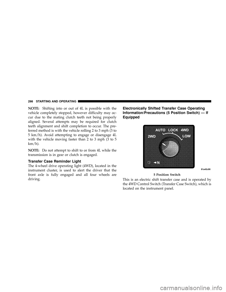
Electronically Shifted Transfer Case Operating
Information/Precautions (5 Position Switch) Ð If
Equipped
This is an electric shift transfer case and is operated by
the 4WD Control Switch (Transfer Case Switch), which is
located on the instrument panel.
5 Position Switch
298 STARTING AND OPERATING
Page 309 of 554
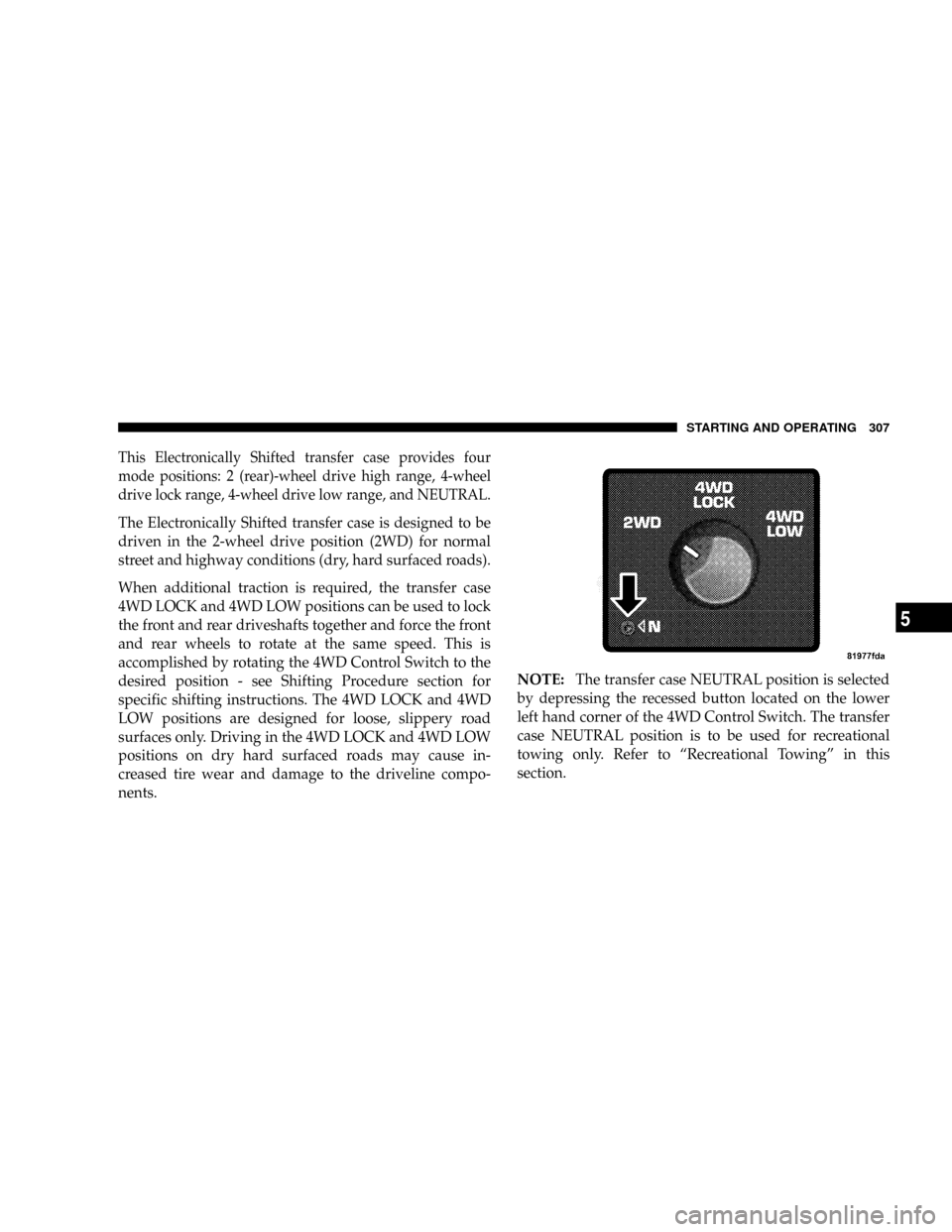
This Electronically Shifted transfer case provides four
mode positions: 2 (rear)-wheel drive high range, 4-wheel
drive lock range, 4-wheel drive low range, and NEUTRAL.
The Electronically Shifted transfer case is designed to be
driven in the 2-wheel drive position (2WD) for normal
street and highway conditions (dry, hard surfaced roads).
When additional traction is required, the transfer case
4WD LOCK and 4WD LOW positions can be used to lock
the front and rear driveshafts together and force the front
and rear wheels to rotate at the same speed. This is
accomplished by rotating the 4WD Control Switch to the
desired position - see Shifting Procedure section for
specific shifting instructions. The 4WD LOCK and 4WD
LOW positions are designed for loose, slippery road
surfaces only. Driving in the 4WD LOCK and 4WD LOW
positions on dry hard surfaced roads may cause in-
creased tire wear and damage to the driveline compo-
nents.NOTE:The transfer case NEUTRAL position is selected
by depressing the recessed button located on the lower
left hand corner of the 4WD Control Switch. The transfer
case NEUTRAL position is to be used for recreational
towing only. Refer to ªRecreational Towingº in this
section.
STARTING AND OPERATING 307
5
Page 322 of 554
3500 Dual Rear Wheel Models Only
The brake system power assist is provided by a hydro-
boost unit which shares fluid with the power steering
system. You may experience some clicking or hissing
noises from the hydro-boost system during hard braking
conditions.
NOTE:Under cold temperatures, pedal effort will be
higher than normal until the power steering fluid reaches
operating temperature.
Brake Noise
During normal operation of the brake system certain
noises may be present from time to time. Occasional
9groan9or9squeal9noises may occur during normal
operation of the brake system which may not be indica-
tive of a problem. These noises may be heard at any time
the brakes are applied but may be more noticeable during
the first few brake applications in the morning. Moisture,
hot or cold temperature, dust, and or other debris mayalso contribute to the noise condition. Repeated or con-
tinuous noises during braking may be an indication that
the brake linings are worn and in need of replacement.
Rear Wheel Anti-Lock (RWAL) Brake System Ð If
Equipped
The Rear-Wheel Anti-Lock Brake System provides in-
creased vehicle stability and brake performance under
most braking conditions. The system automatically con-
trols the operation of the rear brakes to prevent rear
wheel lockup.
The system remains operational in the four-wheel drive
mode. The level of performance is reduced when the
front brakes are locked up. This may cause the rear
brakes to lock up through the drivetrain, which may
reduce the effectiveness of the Anti-Lock Brake System.
During severe braking conditions, particularly with
changing road surfaces, such as ice to concrete, a slight
drop or minor pulsation may be felt in the brake pedal.
320 STARTING AND OPERATING
Page 323 of 554
WARNING!
Both Rear-Wheel and Four-Wheel Anti-Lock Brake
Systems contain sophisticated electronic equipment.
It may be susceptible to interference caused by
improperly installed or high output radio transmit-
ting equipment. This interference can cause possible
loss of anti-lock braking capability. Installation of
such equipment should be performed by qualified
professionals.
Four-Wheel Anti-Lock Brake System Ð If
Equipped
This Four-Wheel Anti-lock Brake System (ABS) is de-
signed to aid the driver in maintaining vehicle control
under adverse braking conditions. The system operateswith a separate computer to modulate hydraulic pressure
to prevent wheel lockup and help avoid skidding on
slippery surfaces.
The system's pump motor runs during an ABS stop to
provide regulated hydraulic pressure. The pump motor
makes a low humming noise during operation. This is
normal.
The ABS conducts a low-speed selftest at about 10 mph
(16 km/h). If you have your foot lightly on the brake
while this test is occurring, you may feel slight pedal
movement. The movement can be more apparent on ice
and snow. This is normal.
The ABS pump motor runs during the self-test at 10 mph
(16 km/h) and during an ABS stop. The pump motor
makes a low humming noise during operation. This is
normal.
STARTING AND OPERATING 321
5
Page 333 of 554
WARNING!
HSA is not a parking brake. If you stop the vehicle on
a hill without putting the transmission in PARK or
using the parking brake, it will roll down the incline
and could cause a collision with another vehicle or
object. Always remember to use the parking brake
while parking on a hill, and that the driver is
responsible for braking the vehicle.
HSA Off
If you wish to turn off the HSA system, follow this
procedure:
1. Start with the engine off and vehicle in PARK (auto-
matic transmission) or NEUTRAL with clutch out
(manual transmission) with wheels straight. Apply park-
ing brake on manual transmission vehicle.2. Start the engine.
3. With the engine running, the brake applied, and the
clutch out, rotate the steering wheel 180É counterclock-
wise from center.
4. Press ESP button four times within twenty seconds.
The ªESP/TCS Indicator Lightº should appear and dis-
appear four times.
5. Rotate the steering wheel 360É clockwise (180É clock-
wise from center).
6. Cycle ignition switch OFF then ON.
7. If the sequence was completed properly, the ªESP/
TCS Indicator Lightº will blink several times to confirm
HSA is off.
Steps 1-7 must be completed within 90 seconds to turn off
HSA. Repeat steps 1-7 to re-enable HSA functionality.
STARTING AND OPERATING 331
5