Page 203 of 527
Two Types of Signals
There are two basic types of radio signals: AM or
Amplitude Modulation, in which the transmitted sound
causes the amplitude, or height, of the radio waves to
vary; and FM or Frequency Modulation, in which the
frequency of the wave is varied to carry the sound.
Electrical Disturbances
Radio waves may pick up electrical disturbances during
transmission. They mainly affect the wave amplitude,
and thus remain a part of the AM reception. They
interfere very little with the frequency variations that
carry the FM signal.
AM Reception
AM sound is based on wave amplitude, so AM reception
can be disrupted by such things as lightning, power lines
and neon signs.
FM Reception
Because FM transmission is based on frequency varia-
tions, interference that consists of amplitude variations
can be filtered out, leaving the reception relatively clear,
which is the major feature of FM radio.
NOTE:The radio, steering wheel radio controls (if
equipped), and 6-disc CD/DVD changer (if equipped)
will remain active for up to 10 minutes after the ignition
switch has been turned OFF. Opening a vehicle front
door will cancel this feature.
UNDERSTANDING YOUR INSTRUMENT PANEL 201
4
Page 248 of 527
REMOTE SOUND SYSTEM CONTROLS Ð IF
EQUIPPED
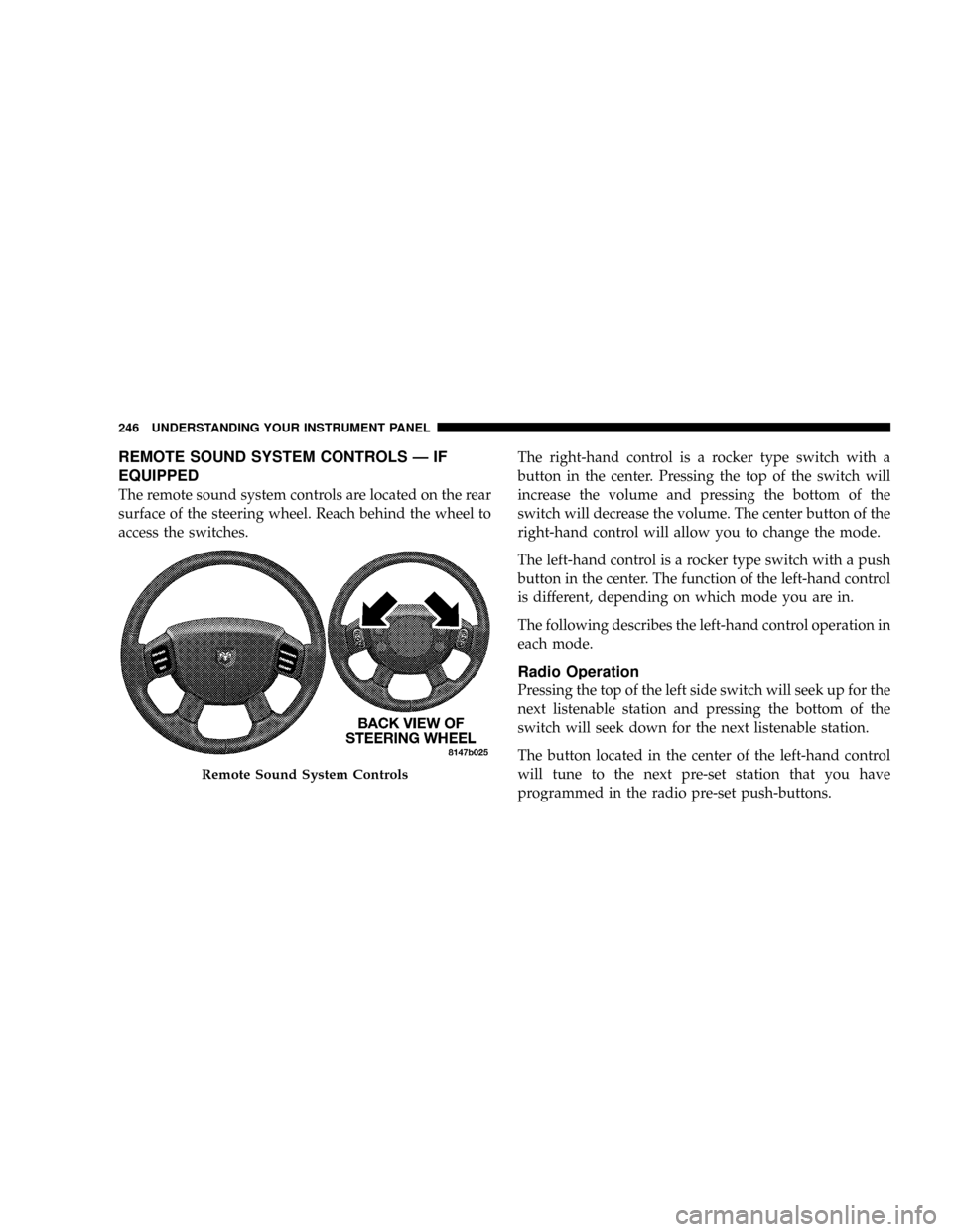
The remote sound system controls are located on the rear
surface of the steering wheel. Reach behind the wheel to
access the switches.The right-hand control is a rocker type switch with a
button in the center. Pressing the top of the switch will
increase the volume and pressing the bottom of the
switch will decrease the volume. The center button of the
right-hand control will allow you to change the mode.
The left-hand control is a rocker type switch with a push
button in the center. The function of the left-hand control
is different, depending on which mode you are in.
The following describes the left-hand control operation in
each mode.
Radio Operation
Pressing the top of the left side switch will seek up for the
next listenable station and pressing the bottom of the
switch will seek down for the next listenable station.
The button located in the center of the left-hand control
will tune to the next pre-set station that you have
programmed in the radio pre-set push-buttons.
Remote Sound System Controls
246 UNDERSTANDING YOUR INSTRUMENT PANEL
Page 266 of 527
mManual Transmission....................291
NShifting............................291
NDownshifting........................293
NReverse Shifting......................294
mFour±Wheel Drive Operation Ð If Equipped . . . 294
NManually Shifted Transfer Case Operating
Information/Precautions................294
NShifting Procedure - Manually Shifted Transfer
Case..............................297
NTransfer Case Reminder Light............298
NElectronically Shifted Transfer Case Operating
Information/Precautions (4 Position Switch) Ð
If Equipped.........................299
NShifting Procedure Ð Electronically Shifted
Transfer Case........................303mLimited-Slip Differential Ð If Equipped.......306
mDriving On Slippery Surfaces..............307
mDriving Through Water..................307
NFlowing/Rising Water..................307
NShallow Standing Water.................308
mDriving Off-Road.......................309
mParking Brake.........................310
mBrake System..........................312
NBrake Noise.........................312
NFour-Wheel Anti-Lock Brake System........313
mPower Steering........................315
mTire Safety Information...................316
NTire Markings........................316
264 STARTING AND OPERATING
Page 267 of 527
NTire Identification Number (TIN)..........319
NTire Loading And Tire Pressure...........320
mTires Ð General Information...............324
NTire Pressure.........................324
NTire Inflation Pressures.................325
NRadial Ply Tires......................327
NCompact Spare Tire Ð If Equipped.........328
NLimited-Use Spare Ð If Equipped.........328
NTire Spinning........................329
NTread Wear Indicators..................330
NLife Of Tire.........................330
NReplacement Tires.....................331
NAlignment And Balance.................332mSupplemental Tire Pressure Information Ð If
Equipped............................333
mTire Chains...........................333
mSnow Tires...........................335
mTire Rotation Recommendations............335
NDual Rear Wheels.....................337
mTire Pressure Monitor System (TPMS) Ð
If Equipped...........................338
NTire Pressure Monitor System (TPMS) ªLight
Loadº Reset Switch Description ±
If Equipped.........................341
NTire Pressure Monitor System Components . . . 344
NGeneral Information...................347
mEngine Runaway.......................347
STARTING AND OPERATING 265
5
Page 269 of 527
mRecreational Towing (Behind Motorhome, Etc.) . . 375
NRecreational Towing ± 2-Wheel Drive
Models............................375NRecreational Towing ± 4-Wheel Drive
Models............................375
STARTING AND OPERATING 267
5
Page 286 of 527
WARNING!
Do not use the Exhaust Brake feature when driving
in icy or slippery conditions as the increased engine
braking can cause the rear wheels to slide and the
vehicle to swing around with the possible loss of
vehicle control, which may cause an accident possi-
bly resulting in personal injury or death.
NOTE:For optimum braking power it is recommended
to use the Exhaust Brake while in Tow/Haul Mode.
The purpose of the exhaust brake (engine braking) fea-
ture is to supply negative (braking) torque to the engine.
Typically, the engine braking is used for, but not limited
to, vehicle towing applications where vehicle braking can
be achieved by the internal engine power, thereby spar-
ing the mechanical brakes of the vehicle.Benefits of the exhaust brake are:²vehicle driving control
²reduced brake fade
²longer brake life
²faster cab warm-up.
The exhaust brake feature can also be used to reduce the
engine warm up time. To use the exhaust brake as a
warm-up device, the vehicle must be moving less than 5
mph (8 km/h), the exhaust brake switch must be in the
ON position, and the coolant temperature must below
180ÉF (82ÉC) and ambient temperature below 60ÉF (16ÉC).
284 STARTING AND OPERATING
Page 287 of 527
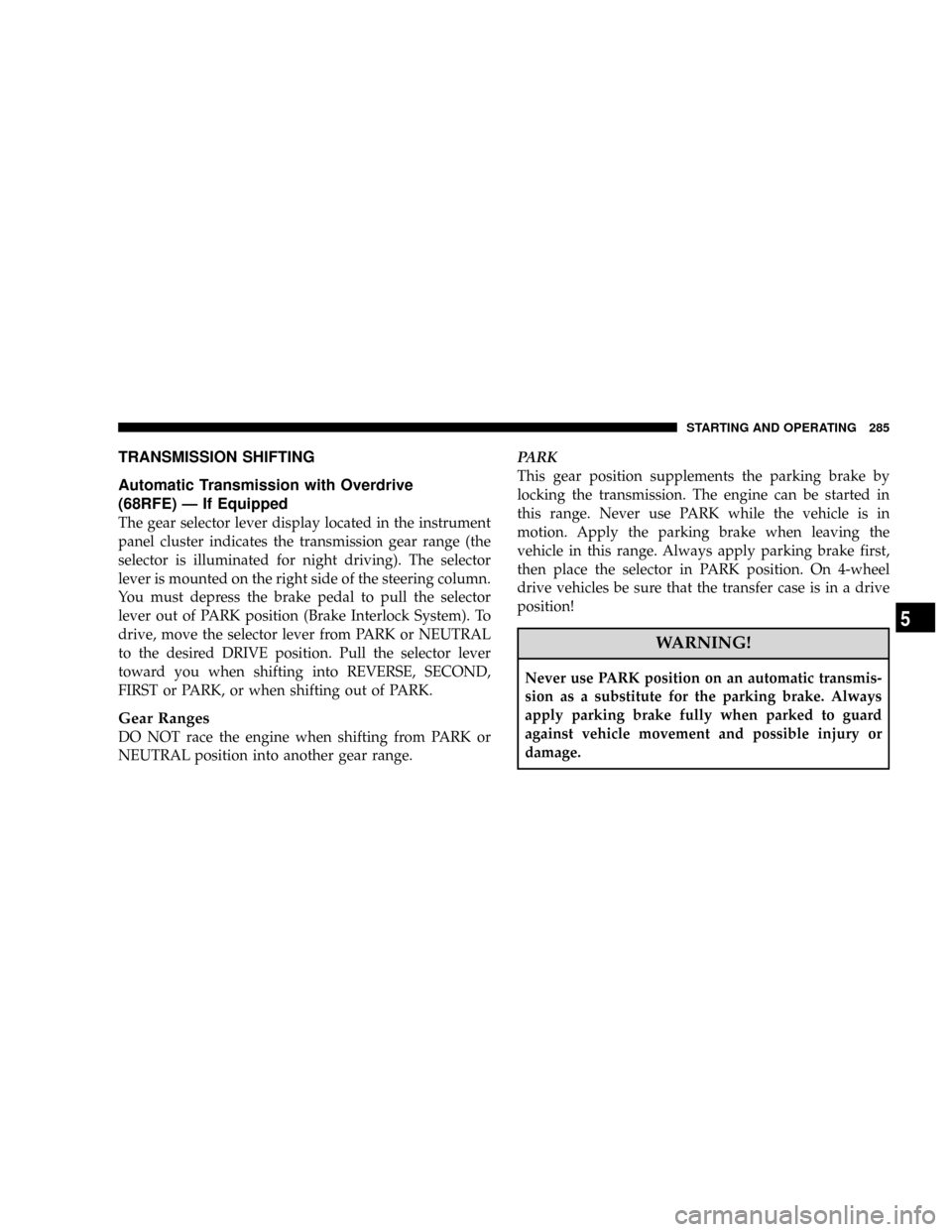
TRANSMISSION SHIFTING
Automatic Transmission with Overdrive
(68RFE) Ð If Equipped
The gear selector lever display located in the instrument
panel cluster indicates the transmission gear range (the
selector is illuminated for night driving). The selector
lever is mounted on the right side of the steering column.
You must depress the brake pedal to pull the selector
lever out of PARK position (Brake Interlock System). To
drive, move the selector lever from PARK or NEUTRAL
to the desired DRIVE position. Pull the selector lever
toward you when shifting into REVERSE, SECOND,
FIRST or PARK, or when shifting out of PARK.
Gear Ranges
DO NOT race the engine when shifting from PARK or
NEUTRAL position into another gear range.PARK
This gear position supplements the parking brake by
locking the transmission. The engine can be started in
this range. Never use PARK while the vehicle is in
motion. Apply the parking brake when leaving the
vehicle in this range. Always apply parking brake first,
then place the selector in PARK position. On 4-wheel
drive vehicles be sure that the transfer case is in a drive
position!
WARNING!
Never use PARK position on an automatic transmis-
sion as a substitute for the parking brake. Always
apply parking brake fully when parked to guard
against vehicle movement and possible injury or
damage.
STARTING AND OPERATING 285
5
Page 291 of 527
delayed. Shifts into 5th and 6th gear are still allowed
under steady cruise conditions. Closed throttle down-
shifts (for improved engine braking) may occur during
steady braking maneuvers. Pressing the switch a second
time restores normal operation. Normal operation is
always the default at engine start-up.
The TOW HAUL light will illuminate in the instrument
cluster to indicate when the switch has been activated. If
the TOW HAUL modes are desired, the button must be
pressed each time the engine is started.
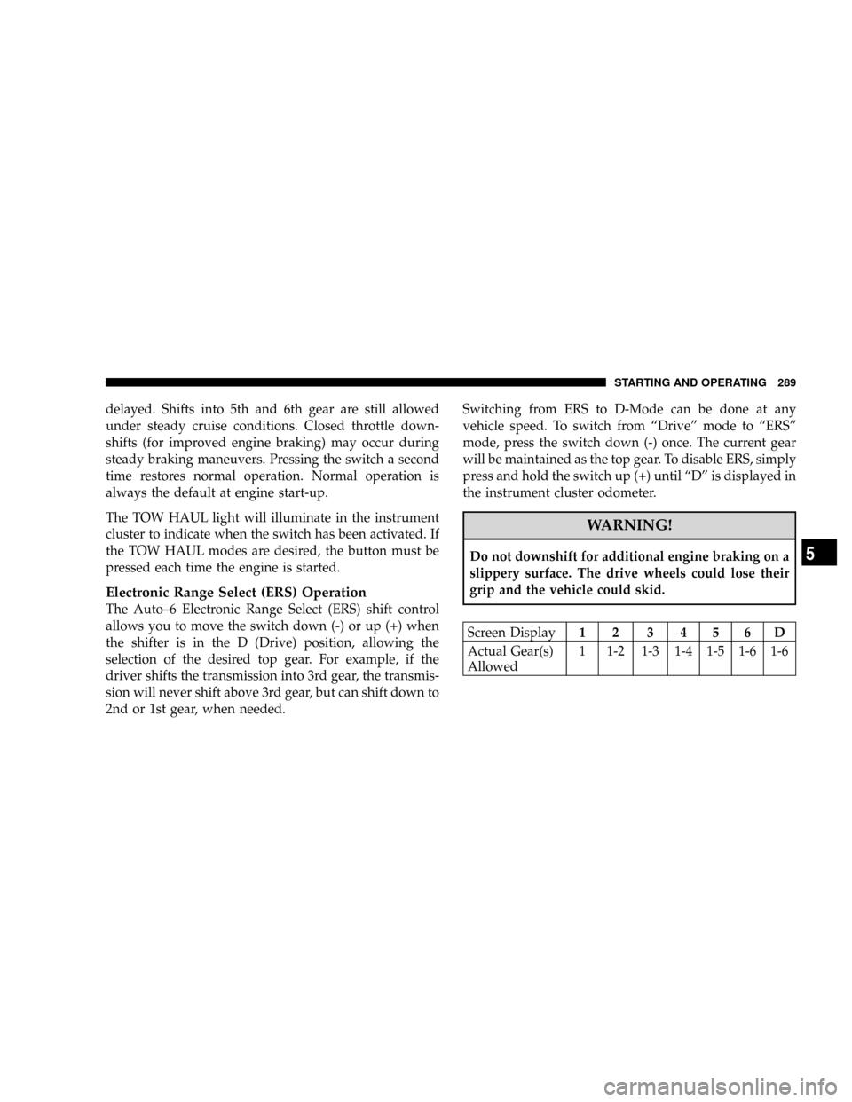
Electronic Range Select (ERS) Operation
The Auto±6 Electronic Range Select (ERS) shift control
allows you to move the switch down (-) or up (+) when
the shifter is in the D (Drive) position, allowing the
selection of the desired top gear. For example, if the
driver shifts the transmission into 3rd gear, the transmis-
sion will never shift above 3rd gear, but can shift down to
2nd or 1st gear, when needed.Switching from ERS to D-Mode can be done at any
vehicle speed. To switch from ªDriveº mode to ªERSº
mode, press the switch down (-) once. The current gear
will be maintained as the top gear. To disable ERS, simply
press and hold the switch up (+) until ªDº is displayed in
the instrument cluster odometer.
WARNING!
Do not downshift for additional engine braking on a
slippery surface. The drive wheels could lose their
grip and the vehicle could skid.
Screen Display12 3456D
Actual Gear(s)
Allowed1 1-2 1-3 1-4 1-5 1-6 1-6
STARTING AND OPERATING 289
5