2008 DODGE RAM 3500 DIESEL four wheel drive
[x] Cancel search: four wheel drivePage 193 of 527
9. Oil Pressure Gauge
The pointer should always indicate some oil pres-
sure when the engine is running. A continuous
high or low reading, under normal driving conditions,
may indicate a lubrication system malfunction. Immedi-
ate service should be obtained.
NOTE:If the gauge pointer moves to either extreme of
the gauge, the ªCheck Gaugesº indicator will illuminate
and a single chime will sound.
10. Transfer Case Position
This display indicator shows the transfer case position
selection.
For additional information refer to ªFour-Wheel Drive
Operationº in Section 5 of this manual.11 .TOW HAUL
The TOW HAUL button is located at the end of the gear
shift lever. This light will illuminate when the TOW
HAUL button is pushed once.
12. Temperature Gauge
The temperature gauge indicates engine coolant
temperature. Any reading within the normal
range indicates that the cooling system is operat-
ing satisfactorily. The gauge needle will likely indicate a
higher temperature when driving in hot weather, up
mountain grades, in heavy traffic, or when towing a
trailer. If the needle rises to the ª245ÉFº (118ÉC) mark,
stop the vehicle, shift into NEUTRAL, and increase the
engine idle speed for two to three minutes. If the tem-
perature reading does not return to normal, shut your
engine OFF and allow it to cool. Seek authorized service
immediately. Refer to ªCooling Systemº under ªMain-
taining Your Vehicleº in Section 7.
UNDERSTANDING YOUR INSTRUMENT PANEL 191
4
Page 266 of 527
mManual Transmission....................291
NShifting............................291
NDownshifting........................293
NReverse Shifting......................294
mFour±Wheel Drive Operation Ð If Equipped . . . 294
NManually Shifted Transfer Case Operating
Information/Precautions................294
NShifting Procedure - Manually Shifted Transfer
Case..............................297
NTransfer Case Reminder Light............298
NElectronically Shifted Transfer Case Operating
Information/Precautions (4 Position Switch) Ð
If Equipped.........................299
NShifting Procedure Ð Electronically Shifted
Transfer Case........................303mLimited-Slip Differential Ð If Equipped.......306
mDriving On Slippery Surfaces..............307
mDriving Through Water..................307
NFlowing/Rising Water..................307
NShallow Standing Water.................308
mDriving Off-Road.......................309
mParking Brake.........................310
mBrake System..........................312
NBrake Noise.........................312
NFour-Wheel Anti-Lock Brake System........313
mPower Steering........................315
mTire Safety Information...................316
NTire Markings........................316
264 STARTING AND OPERATING
Page 296 of 527
Maximum Recommended Downshifting Speeds
Gear
Selec-
tion6to5 5to4 4to3 3to2 2toL
Maxi-
mum
Speed68 mph
(109
km/h)50 mph
(80
km/h)32 mph
(51
km/h)19 mph
(31
km/h)10 mph
(16
km/h)
Reverse Shifting
To shift into REVERSE (R), bring the vehicle to a com-
plete stop. Depress the clutch and pause briefly to allow
the gear train to stop rotating. Beginning from the
NEUTRAL (N) position, move the shift lever in one quick
smooth motion straight across and into the REVERSE (R)
area (the driver will feel a firm ªclickº as the shifter
passes the ªknock-overº). Complete the shift by pulling
the shift lever into REVERSE (R).
The ªknock-overº prevents the driver from accidentally
entering the REVERSE (R) shift area and warns the driverthat they are about to shift the transmission into RE-
VERSE (R). Due to this feature, a slow shift to REVERSE
(R) can be perceived as a high shift effort.
To shift out of reverse bring the vehicle to a complete stop
and depress the clutch. Shifting out of reverse prior to a
complete stop may cause high shift effort.
FOUR±WHEEL DRIVE OPERATION Ð IF
EQUIPPED
Four-Wheel Drive trucks are equipped with either a
manually shifted transfer case or an electronically shifted
transfer case. See the operating instructions for your
transfer case, located within this section.
Manually Shifted Transfer Case Operating
Information/Precautions
The transfer case provides 4 mode positions-2(rear)-
wheel drive high range, 4-wheel drive high range, neu-
tral, and 4-wheel drive low range.
294 STARTING AND OPERATING
Page 298 of 527
NOTE:Delayed shifts out of four-wheel drive may be
experienced due to uneven tire wear, low or uneven tire
pressures, excessive vehicle loading, or cold tempera-
tures.
WARNING!
You or others could be injured if you leave the
vehicle unattended with the transfer case in the
NEUTRAL position without first fully engaging the
parking brake. The transfer case NEUTRAL position
disengages both the front and rear driveshafts from
the powertrain and will allow the vehicle to move
regardless of the transmission position. The parking
brake should always be applied when the driver is
not in the vehicle.For additional information on the appropriate use of each
transfer case mode position see the information below:
2H
Rear Wheel Drive High Range - Normal street and
highway driving. Dry hard surfaced roads.
4H
4-Wheel Drive High Range - Locks the front and rear
driveshafts together. Forces the front and rear wheels to
rotate at the same speed. Additional traction for loose,
slippery road surfaces only.
N
NEUTRAL - Disengages both the front and rear drive-
shafts from the powertrain. To be used for flat towing
behind another vehicle. See Recreational Towing for
more information.
296 STARTING AND OPERATING
Page 300 of 527
vehicle in motion, the transfer case will engage/
disengage faster if you momentarily release the accelera-
tor pedal after completing the shift. Apply a constant
force when shifting the transfer case lever.
2H or 4H,4L
With the vehicle rolling at 2 to 3 mph (3 to 5 km/h), shift
an automatic transmission to NEUTRAL or depress the
clutch on a manual transmission. While the vehicle is
coasting at 2 to 3 mph (3 to 5 km/h), shift the transfer
case lever firmly to the desired position. Do not pause in
transfer case NEUTRAL.
NOTE:Pausing in transfer case NEUTRAL in vehicles
equipped with an automatic transmission may require
shutting the engine OFF to avoid gear clash while
completing the shift. If difficulty occurs, shift automatic
transmission to NEUTRAL, hold foot on brake, and turn
engine OFF. Make shift to the desired mode.NOTE:Shifting into or out of 4L is possible with the
vehicle completely stopped, however difficulty may oc-
cur due to the mating clutch teeth not being properly
aligned. Several attempts may be required for clutch
teeth alignment and shift completion to occur. The pre-
ferred method is with the vehicle rolling 2 to 3 mph (3 to
5 km/h). Avoid attempting to engage or disengage 4L
with the vehicle moving faster than 2 to 3 mph (3 to 5
km/h).
NOTE:Do not attempt to shift to or from 4L while the
transmission is in gear or clutch is engaged.
Transfer Case Reminder Light
The four-wheel drive operating light (4WD), located in
the instrument cluster, is used to alert the driver that the
front axle is fully engaged and all four wheels are
driving.
298 STARTING AND OPERATING
Page 301 of 527
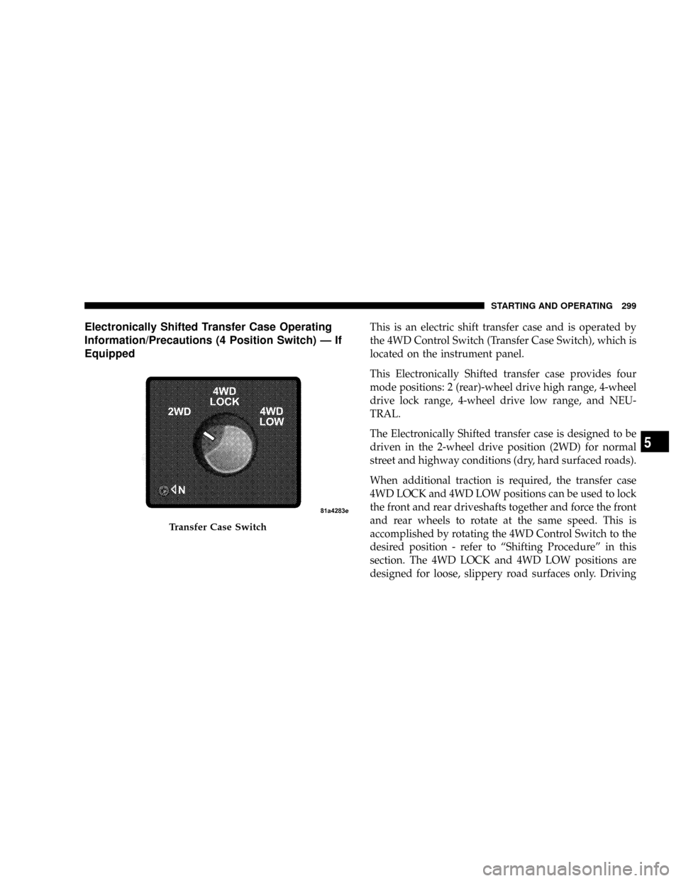
Electronically Shifted Transfer Case Operating
Information/Precautions (4 Position Switch) Ð If
EquippedThis is an electric shift transfer case and is operated by
the 4WD Control Switch (Transfer Case Switch), which is
located on the instrument panel.
This Electronically Shifted transfer case provides four
mode positions: 2 (rear)-wheel drive high range, 4-wheel
drive lock range, 4-wheel drive low range, and NEU-
TRAL.
The Electronically Shifted transfer case is designed to be
driven in the 2-wheel drive position (2WD) for normal
street and highway conditions (dry, hard surfaced roads).
When additional traction is required, the transfer case
4WD LOCK and 4WD LOW positions can be used to lock
the front and rear driveshafts together and force the front
and rear wheels to rotate at the same speed. This is
accomplished by rotating the 4WD Control Switch to the
desired position - refer to ªShifting Procedureº in this
section. The 4WD LOCK and 4WD LOW positions are
designed for loose, slippery road surfaces only. Driving
Transfer Case Switch
STARTING AND OPERATING 299
5
Page 315 of 527
Four-Wheel Anti-Lock Brake System
WARNING!
Anti-Lock Brake Systems contain sophisticated elec-
tronic equipment. It may be susceptible to interfer-
ence caused by improperly installed or high output
radio transmitting equipment. This interference can
cause possible loss of anti-lock braking capability.
Installation of such equipment should be performed
by qualified professionals.
WARNING!
²Anti-lock Brake System (ABS) cannot prevent the
natural laws of physics from acting on the vehicle,
nor can it increase braking or steering efficiency
beyond that afforded by the condition of the
vehicle brakes and tires or the traction afforded.
²The ABS cannot prevent accidents, including
those resulting from excessive speed in turns,
following another vehicle too closely, or hydro-
planing. Only a safe, attentive, and skillful driver
can prevent accidents.
²The capabilities of an ABS equipped vehicle must
never be exploited in a reckless or dangerous
manner which could jeopardize the user's safety
or the safety of others.
STARTING AND OPERATING 313
5
Page 329 of 527
Tire Pressures for High Speed Operation
The manufacturer advocates driving at safe speeds
within posted speed limits. Where speed limits or condi-
tions are such that the vehicle can be driven at high
speeds, maintaining correct tire inflation pressure is very
important. Increased tire pressure and reduced vehicle
loading may be required for high-speed vehicle opera-
tion. Refer to original equipment or an authorized tire
dealer for recommended safe operating speeds, loading
and cold tire inflation pressures.
WARNING!
High speed driving with your vehicle under maxi-
mum load is dangerous. The added strain on your
tires could cause them to fail. You could have a
serious accident. Don't drive a vehicle loaded to the
maximum capacity at continuous speeds above 75
mph (120 km/h).
Radial Ply Tires
WARNING!
Combining radial ply tires with other types of tires
on your vehicle will cause your vehicle to handle
poorly. The instability could cause an accident. Al-
ways use radial ply tires in sets of four (or six, in case
of trucks with dual rear wheels). Never combine
them with other types of tires.
Cuts and punctures in radial tires are repairable only in
the tread area because of sidewall flexing. Consult your
authorized tire dealer for radial tire repairs.
STARTING AND OPERATING 327
5