2008 DODGE RAM 3500 DIESEL flat tire
[x] Cancel search: flat tirePage 198 of 527
experience reduced performance, an elevated/rough idle
or engine stall and your vehicle may require towing. The
light will come on when the ignition is first turned on
and remain on for 15 seconds as a bulb check. If the light
does not come on during starting, have the system
checked by an authorized dealer.
22. SERV 4WD Indicator
The 4WD indicator will be illuminated whenever the
4WD mode is engaged for either the manual or electric
shift 4WD systems. The SERV 4WD indicator monitors
the electric shift 4WD system. If the SERV 4WD light
stays on or comes on during driving, it means that the
4WD system is not functioning properly and that service
is required.23. Water In Fuel Indicator
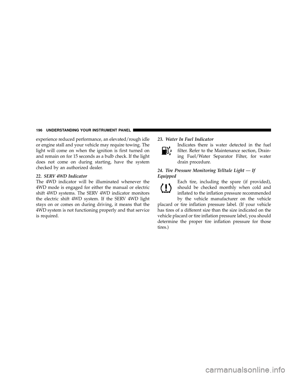
Indicates there is water detected in the fuel
filter. Refer to the Maintenance section, Drain-
ing Fuel/Water Separator Filter, for water
drain procedure.
24. Tire Pressure Monitoring Telltale Light Ð If
Equipped
Each tire, including the spare (if provided),
should be checked monthly when cold and
inflated to the inflation pressure recommended
by the vehicle manufacturer on the vehicle
placard or tire inflation pressure label. (If your vehicle
has tires of a different size than the size indicated on the
vehicle placard or tire inflation pressure label, you should
determine the proper tire inflation pressure for those
tires.)
196 UNDERSTANDING YOUR INSTRUMENT PANEL
Page 199 of 527
As an added safety feature, your vehicle has been
equipped with a tire pressure monitoring system (TPMS)
that illuminates a low tire pressure telltale when one or
more of your tires is significantly under-inflated. Accord-
ingly, when the low tire pressure telltale illuminates, you
should stop and check your tires as soon as possible, and
inflate them to the proper pressure. Driving on a signifi-
cantly under-inflated tire causes the tire to overheat and
can lead to tire failure. Under-inflation also reduces fuel
efficiency and tire tread life, and may affect the vehicle's
handling and stopping ability.
Please note that the TPMS is not a substitute for proper
tire maintenance, and it is the driver 's responsibility to
maintain correct tire pressure, even if under-inflation has
not reached the level to trigger illumination of the TPMS
low tire pressure telltale.Your vehicle has also been equipped with a TPMS
malfunction indicator to indicate when the system is not
operating properly. The TPMS malfunction indicator is
combined with the low tire pressure telltale. When the
system detects a malfunction, the telltale will flash for
approximately one minute and then remain continuously
illuminated. This sequence will continue upon subse-
quent vehicle start-ups as long as the malfunction exists.
When the malfunction indicator is illuminated, the sys-
tem may not be able to detect or signal low tire pressure
as intended. TPMS malfunctions may occur for a variety
of reasons, including the installation of replacement or
alternate tires or wheels on the vehicle that prevent the
TPMS from functioning properly. Always check the
TPMS malfunction telltale after replacing one or more
tires or wheels on your vehicle to ensure that the replace-
ment or alternate tires and wheels allow the TPMS to
continue to function properly.
UNDERSTANDING YOUR INSTRUMENT PANEL 197
4
Page 267 of 527
NTire Identification Number (TIN)..........319
NTire Loading And Tire Pressure...........320
mTires Ð General Information...............324
NTire Pressure.........................324
NTire Inflation Pressures.................325
NRadial Ply Tires......................327
NCompact Spare Tire Ð If Equipped.........328
NLimited-Use Spare Ð If Equipped.........328
NTire Spinning........................329
NTread Wear Indicators..................330
NLife Of Tire.........................330
NReplacement Tires.....................331
NAlignment And Balance.................332mSupplemental Tire Pressure Information Ð If
Equipped............................333
mTire Chains...........................333
mSnow Tires...........................335
mTire Rotation Recommendations............335
NDual Rear Wheels.....................337
mTire Pressure Monitor System (TPMS) Ð
If Equipped...........................338
NTire Pressure Monitor System (TPMS) ªLight
Loadº Reset Switch Description ±
If Equipped.........................341
NTire Pressure Monitor System Components . . . 344
NGeneral Information...................347
mEngine Runaway.......................347
STARTING AND OPERATING 265
5
Page 298 of 527
NOTE:Delayed shifts out of four-wheel drive may be
experienced due to uneven tire wear, low or uneven tire
pressures, excessive vehicle loading, or cold tempera-
tures.
WARNING!
You or others could be injured if you leave the
vehicle unattended with the transfer case in the
NEUTRAL position without first fully engaging the
parking brake. The transfer case NEUTRAL position
disengages both the front and rear driveshafts from
the powertrain and will allow the vehicle to move
regardless of the transmission position. The parking
brake should always be applied when the driver is
not in the vehicle.For additional information on the appropriate use of each
transfer case mode position see the information below:
2H
Rear Wheel Drive High Range - Normal street and
highway driving. Dry hard surfaced roads.
4H
4-Wheel Drive High Range - Locks the front and rear
driveshafts together. Forces the front and rear wheels to
rotate at the same speed. Additional traction for loose,
slippery road surfaces only.
N
NEUTRAL - Disengages both the front and rear drive-
shafts from the powertrain. To be used for flat towing
behind another vehicle. See Recreational Towing for
more information.
296 STARTING AND OPERATING
Page 309 of 527
DRIVING ON SLIPPERY SURFACES
When driving on wet or slushy roads, it is possible for a
wedge of water to build up between the tire and road
surface. This is known as hydroplaning and may cause
partial or complete loss of vehicle control and stopping
ability. To reduce this possibility, the following precau-
tions should be observed:
1. Slow down during rainstorms or when roads are
slushy.
2. Slow down if road has standing water or puddles.
3. Replace tires when tread wear indicators first become
visible.
4. Keep tires properly inflated.
5. Maintain sufficient distance between your vehicle and
the car in front to avoid a collision in a sudden stop.
DRIVING THROUGH WATER
Driving through water more than a few inches/
centimeters deep will require extra caution to ensure
safety and prevent damage to your vehicle.
Flowing/Rising Water
WARNING!
Do not drive on, or cross, a road or a path where
water is flowing and/or rising (as in storm run-off).
Flowing water can wear away the road or path's
surface and cause your vehicle to sink into deeper
water. Furthermore, flowing and/or rising water can
carry your vehicle away swiftly. Failure to follow this
warning may result in injuries that are serious or
fatal to you, your passengers, and others around you.
STARTING AND OPERATING 307
5
Page 320 of 527
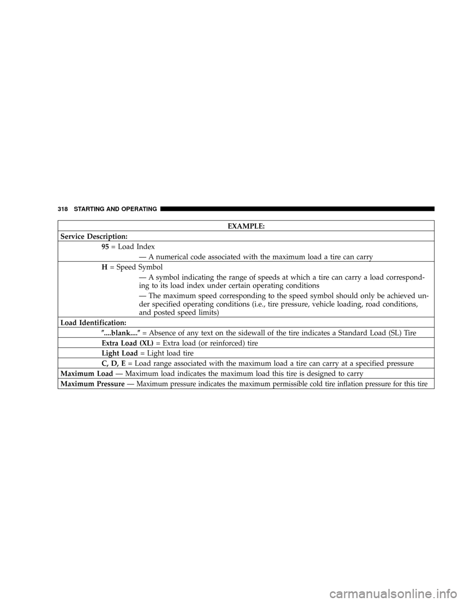
EXAMPLE:
Service Description:
95= Load Index
Ð A numerical code associated with the maximum load a tire can carry
H= Speed Symbol
Ð A symbol indicating the range of speeds at which a tire can carry a load correspond-
ing to its load index under certain operating conditions
Ð The maximum speed corresponding to the speed symbol should only be achieved un-
der specified operating conditions (i.e., tire pressure, vehicle loading, road conditions,
and posted speed limits)
Load Identification:
(....blank....(= Absence of any text on the sidewall of the tire indicates a Standard Load (SL) Tire
Extra Load (XL)= Extra load (or reinforced) tire
Light Load= Light load tire
C, D, E= Load range associated with the maximum load a tire can carry at a specified pressure
Maximum LoadÐ Maximum load indicates the maximum load this tire is designed to carry
Maximum PressureÐ
Maximum pressure indicates the maximum permissible cold tire inflation pressure for this tire
318 STARTING AND OPERATING
Page 322 of 527
Tire Loading and Tire Pressure
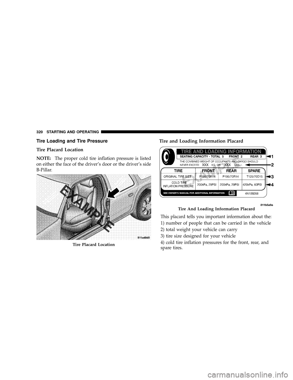
Tire Placard Location
NOTE:The proper cold tire inflation pressure is listed
on either the face of the driver's door or the driver's side
B-Pillar.
Tire and Loading Information Placard
This placard tells you important information about the:
1) number of people that can be carried in the vehicle
2) total weight your vehicle can carry
3) tire size designed for your vehicle
4) cold tire inflation pressures for the front, rear, and
spare tires.
Tire Placard Location
Tire And Loading Information Placard
320 STARTING AND OPERATING
Page 323 of 527
Loading
The vehicle maximum load on the tire must not exceed
the load carrying capacity of the tire on your vehicle. You
will not exceed the tire's load carrying capacity if you
adhere to the loading conditions, tire size, and cold tire
inflation pressures specified on the Tire and Loading
Information placard and in the ªVehicle Loadingº section
of this manual.
NOTE:Under a maximum loaded vehicle condition,
gross axle weight ratings (GAWRs) for the front and rear
axles must not be exceeded. For further information on
GAWRs, vehicle loading, and trailer towing, refer to
ªVehicle Loadingº in this section.
To determine the maximum loading conditions of your
vehicle, locate the statement ªThe combined weight of
occupants and cargo should never exceed XXX kg or XXX
lbs.º on the Tire and Loading Information placard. Thecombined weight of occupants, cargo/luggage and
trailer tongue weight (if applicable) should never exceed
the weight referenced here.
Steps for Determining Correct Load Limit
1. Locate the statement ªThe combined weight of occu-
pants and cargo should never exceed XXX lbs or XXX kgº
on your vehicle's placard.
2. Determine the combined weight of the driver and
passengers that will be riding in your vehicle.
3. Subtract the combined weight of the driver and pas-
sengers from XXX kg or XXX lbs.
4. The resulting figure equals the available amount of
cargo and luggage load capacity. For example, if ªXXXº
amount equals 1,400 lbs (635 kg) and there will be five
150 lb (68 kg) passengers in your vehicle, the amount of
STARTING AND OPERATING 321
5