Page 347 of 527
NOTE:It is particularly important, for you to check the
tire pressure in all of your tires regularly and to maintain
the proper pressure.
The Tire Pressure Monitoring System (TPMS) consists of
the following components:
²Receiver Module
²4 Wheel Sensors
²2 Trigger Modules (mounted in the front wheel-wells)
²ªLight Loadº Reset Switch (located in the instrument
panel)
²Tire Pressure Monitoring Telltale Lamp
Tire Pressure Monitoring Low Pressure Warnings
The Tire Pressure Monitoring Telltale Lamp will
illuminate in the instrument cluster, and an au-
dible chime will be activated when one or more of
the four active road tire pressures are low. Should this
occur, you should stop as soon as possible, check the
inflation pressure of each tire on your vehicle and inflate
each tire to the vehicle's recommended cold placard
pressure value. The system will automatically update
and the Tire Pressure Monitoring Lamp will extinguish
once the updated tire pressures have been received. The
vehicle may need to be driven for up to 10 minutes above
15 mph (25 km/h) to receive this information.
Check TPMS Warnings
The Tire Pressure Monitoring Telltale Warning Light
located in the Instrument Cluster will flash on and off for
75 seconds and will remain on solid when a system fault
is detected. The system fault will also sound a chime. If
STARTING AND OPERATING 345
5
Page 355 of 527
Gross Vehicle Weight Rating (GVWR)
The GVWR is the total permissible weight of your vehicle
including driver, passengers, vehicle, options and cargo.
The label also specifies maximum capacities of front and
rear axle systems (GAWR). Total load must be limited so
GVWR and front and rear GAWR are not exceeded.
Payload
The payload of a vehicle is defined as the allowable load
weight a truck can carry, including the weight of the
driver, all passengers, options and cargo.
Gross Axle Weight Rating (GAWR)
The GAWR is the maximum permissible load on the front
and rear axles. The load must be distributed in the cargo
area so that the GAWR of each axle is not exceeded.Each axle GAWR is determined by the components in the
system with the lowest load carrying capacity (axle,
springs, tires or wheels). Heavier axles or suspension
components sometimes specified by purchasers for in-
creased durability does not necessarily increase the vehi-
cle's GVWR.
Tire Size
The tire size on the Label represents the actual tire size on
your vehicle. Replacement tires must be equal to the load
capacity of this tire size.
Rim Size
This is the rim size that is appropriate for the tire size
listed.
Inflation Pressure
This is the cold tire inflation pressure for your vehicle for
all loading conditions up to full GAWR.
STARTING AND OPERATING 353
5
Page 366 of 527
2. GTW
3. GAWR
4. Tongue weight rating for the trailer hitch utilized
(This requirement may limit the ability to always
achieve the 10% to 15% range of tongue weight as a
percentage of total trailer weight).
Towing Requirements Ð Tires
þ
Do not attempt to tow a trailer while using a compact
spare tire.
þProper tire inflation pressures are essential to the safe
and satisfactory operation of your vehicle. Refer to the
Tires±General Information section of this manual on
Tire Pressures for proper tire inflation procedures.
þAlso, check the trailer tires for proper tire inflation
pressures before trailer usage.
þCheck for signs of tire wear or visible tire damage
before towing a trailer. Refer to the Tires±General
Information section of this manual on Tread Wear
Indicators for the proper inspection procedure.
þWhen replacing tires refer to the Tires±General Infor-
mation section of this manual on Replacement Tires for
proper tire replacement procedures. Replacing tires
with a higher load carrying capacity will not increase
the vehicle's GVWR and GAWR limits.
Towing Requirements Ð Trailer Brakes
þ
Donotinterconnect the hydraulic brake system or
vacuum system of your vehicle with that of the trailer.
This could cause inadequate braking and possible
personal injury.
364 STARTING AND OPERATING
Page 388 of 527
WARNING!
After using the jack and tools, always reinstall them
in the original carrier and location. While driving
you may experience, abrupt stopping, rapid accelera-
tion, or sharp turns. A loose jack, tools, bracket or
other objects in the vehicle may move around with
force, resulting in serious injury.
JACKING INSTRUCTIONS
Removing The Spare Tire
Remove the spare tire before attempting to jack the truck.
Attach the wheel wrench to the jack extension tube. Insert
the tube through the access hole between the lower
tailgate and the top of the bumper and into the winch
mechanism tube. Rotate the wheel wrench handle coun-
terclockwise until the spare tire is on the ground with
enough cable slack to allow you to pull it out from underthe vehicle. When the spare is clear, tilt the retainer at the
end of the cable and pull it through the center of the
wheel.
It is recommended that you stow the flat or spare to
avoid tangling the loose cable.
386 WHAT TO DO IN EMERGENCIES
Page 393 of 527
4. By rotating the wheel wrench clockwise, raise the
vehicle until the wheel just clears the surface.
WARNING!
Raising the vehicle higher than necessary can make
the vehicle unstable and cause an accident. It could
slip off the jack and hurt someone near it. Raise the
vehicle only enough to remove the tire.
5. Remove the wheel nuts and pull the wheel off. Install
the spare wheel and wheel nuts with the cone shaped end
of the nuts toward the wheel on 2500/3500 single rear
wheel (SRW) models. On 3500 dual rear wheel models
(DRW) the lug nuts are a two piece assembly with a flat
face. Lightly tighten the nuts. To avoid risk of forcing the
vehicle off the jack, do not fully tighten the nuts until the
vehicle has been lowered.
WHAT TO DO IN EMERGENCIES 391
6
Page 395 of 527
On 3500 models with dual rear wheels (DRW), you must
first remove the hub caps. The jack handle driver has a
hook at one end that will fit in the pry off notch of the
rear hub caps. Position the hook and pull out on the
ratchet firmly. The hub cap should pop off. The wheel
skins can now be removed. For the front hub cap on 3500
models use the blade on the end of the lug wrench to pry
the caps off. The wheel skin can now be removed.
CAUTION!
Use a back and forth motion to remove the hub cap.
Do not use a twisting motion when removing the hub
cap, damage to the hub cap finish may occur.
CAUTION!
The rear hub caps on the dual rear wheel has two pry
off notches. Make sure that the hook of the jack
handle driver is located squarely in the cap notch
before attempting to pull off.
You must use the flat end of the lug wrench to pry off the
wheel skins. Insert the flat tip completely and using a
back and forth motion, loosen the wheel skin. Repeat this
procedure around the tire until the skin pops off.
Replace the wheel skins first using a rubber mallet. When
replacing the hub caps, tilt the cap retainer over the
lugnut bolt circle and strike the high side down with a
rubber mallet. Be sure that the hub caps and wheel skins
are firmly seated around the wheel.
WHAT TO DO IN EMERGENCIES 393
6
Page 396 of 527
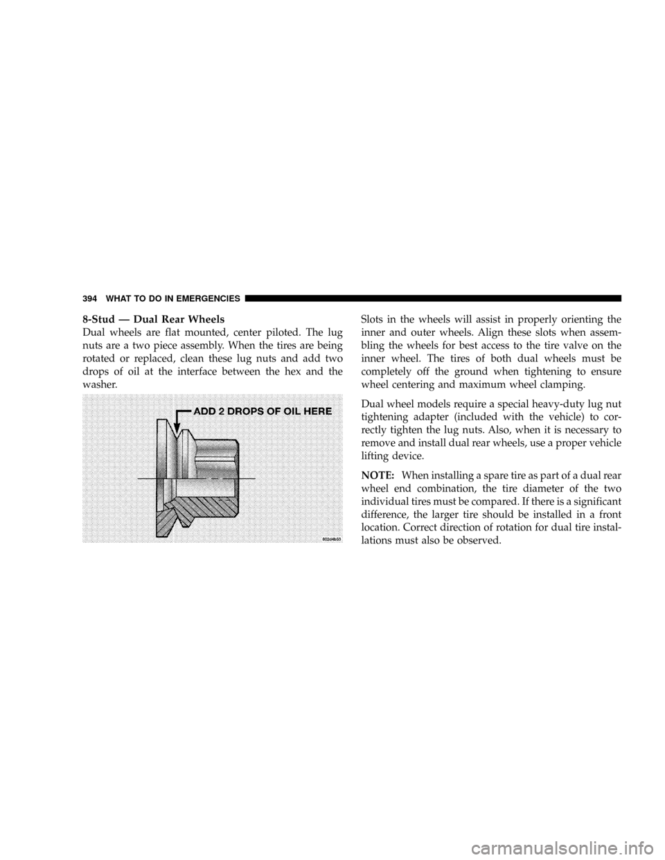
8-Stud Ð Dual Rear Wheels
Dual wheels are flat mounted, center piloted. The lug
nuts are a two piece assembly. When the tires are being
rotated or replaced, clean these lug nuts and add two
drops of oil at the interface between the hex and the
washer.Slots in the wheels will assist in properly orienting the
inner and outer wheels. Align these slots when assem-
bling the wheels for best access to the tire valve on the
inner wheel. The tires of both dual wheels must be
completely off the ground when tightening to ensure
wheel centering and maximum wheel clamping.
Dual wheel models require a special heavy-duty lug nut
tightening adapter (included with the vehicle) to cor-
rectly tighten the lug nuts. Also, when it is necessary to
remove and install dual rear wheels, use a proper vehicle
lifting device.
NOTE:When installing a spare tire as part of a dual rear
wheel end combination, the tire diameter of the two
individual tires must be compared. If there is a significant
difference, the larger tire should be installed in a front
location. Correct direction of rotation for dual tire instal-
lations must also be observed.
394 WHAT TO DO IN EMERGENCIES
Page 398 of 527
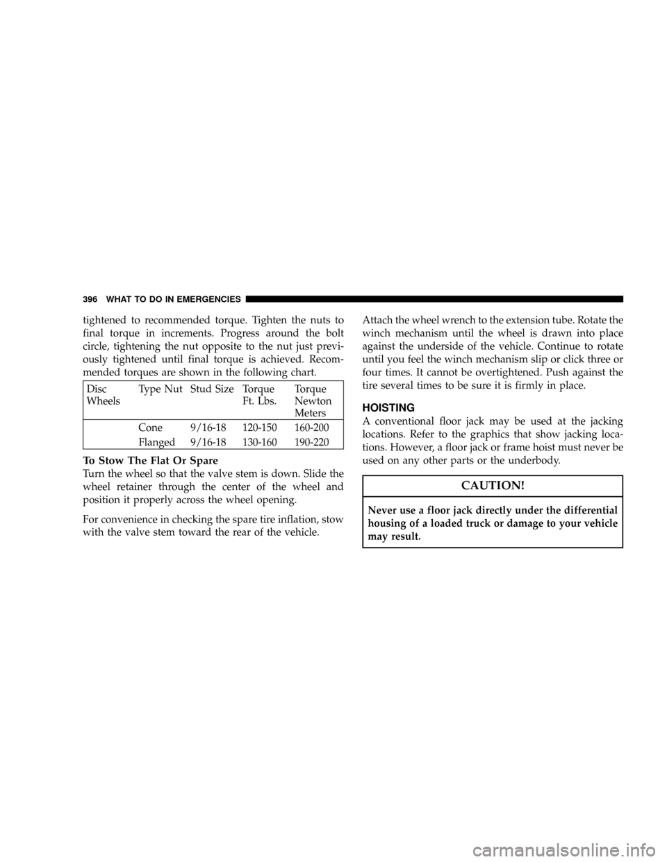
tightened to recommended torque. Tighten the nuts to
final torque in increments. Progress around the bolt
circle, tightening the nut opposite to the nut just previ-
ously tightened until final torque is achieved. Recom-
mended torques are shown in the following chart.
Disc
WheelsType Nut Stud Size Torque
Ft. Lbs.Torque
Newton
Meters
Cone 9/16-18 120-150 160-200
Flanged 9/16-18 130-160 190-220
To Stow The Flat Or Spare
Turn the wheel so that the valve stem is down. Slide the
wheel retainer through the center of the wheel and
position it properly across the wheel opening.
For convenience in checking the spare tire inflation, stow
with the valve stem toward the rear of the vehicle.Attach the wheel wrench to the extension tube. Rotate the
winch mechanism until the wheel is drawn into place
against the underside of the vehicle. Continue to rotate
until you feel the winch mechanism slip or click three or
four times. It cannot be overtightened. Push against the
tire several times to be sure it is firmly in place.
HOISTING
A conventional floor jack may be used at the jacking
locations. Refer to the graphics that show jacking loca-
tions. However, a floor jack or frame hoist must never be
used on any other parts or the underbody.
CAUTION!
Never use a floor jack directly under the differential
housing of a loaded truck or damage to your vehicle
may result.
396 WHAT TO DO IN EMERGENCIES