2008 CHRYSLER TOWN AND COUNTRY ESP
[x] Cancel search: ESPPage 175 of 531
WARNING!
Drivers must be careful when backing up even when
using the Rear Park Assist System. Always check care-
fully behind your vehicle, and be sure to check for
pedestrians, animals, other vehicles, obstructions, or blind
spots before backing up. You are responsible for the safety
of your surroundings and must continue to pay attention
while backing up. Failure to do so can result in serious
injury or death.
Before using the Rear Park Assist System, it is strongly
recommended that the ball mount and hitch ball assembly
be disconnected from the vehicle when the vehicle is not
used for towing. Failure to do so can result in injury or
damage to vehicles or obstacles because the hitch ball will
be much closer to the obstacle than the rear fascia when
the warning display turns the red LEDs on. Also, the
sensors could detect the ball mount and hitch ball assem-
bly, depending on its size and shape, giving a false
indication that an obstacle is behind the vehicle.
CAUTION!
²To avoid vehicle damage the Rear Park Assist
System should only be used as a parking aid and
is unable to recognize every obstacle, including
small objects. Parking curbs might be temporarily
detected or not detected at all. Obstacles located
above or below the sensors will not be detected
when they are in close proximity to the rear of the
vehicle.
²To avoid vehicle damage the vehicle must be
driven slowly when using the Rear Park Assist
System to be able to stop in time when an obstacle
is detected. It is recommended that the driver look
over his/her shoulder when using the Rear Park
Assist System.
UNDERSTANDING THE FEATURES OF YOUR VEHICLE 173
3
Page 191 of 531
TROUBLESHOOTING TIPS
If you are having trouble programming HomeLinkt, here
are some of the most common solutions:
²Replace the battery in the original transmitter.
²Press the ªLearnº button on the Garage Door Opener
to complete the training for a Rolling Code.
²Did you unplug the device for training, and remember
to plug it back in?
If you have any problems, or require assistance, please
call toll-free 1±800±355±3515 or, on the Internet at
www.HomeLink.com for information or assistance.
GENERAL INFORMATION
This device complies with FCC rules Part 15 and Industry
Canada RSS-210. Operation is subject to the following
two conditions:
1. This device may not cause harmful interference.2. This device must accept any interference that may be
received including interference that may cause undesired
operation.
NOTE:The transmitter has been tested and it complies
with FCC and IC rules. Changes or modifications not
expressly approved by the party responsible for compli-
ance could void the user 's authority to operate the
device.
The term IC before the certification/registration number
only signifies that Industry Canada technical specifica-
tions were met.
POWER SUNROOF Ð IF EQUIPPED
The power sunroof control switch is located in the front
overhead console.
The sunroof panel tilts upward at the rear for ventilation
or slides rearward under the roof.
UNDERSTANDING THE FEATURES OF YOUR VEHICLE 189
3
Page 217 of 531
CAUTION!
²Long loads which extend over the windshield,
such as wood panels or surfboards, or loads with
large frontal area should be secured to both the
front and rear of the vehicle.
²Travel at reduced speeds and turn corners care-
fully when carrying large or heavy loads on the
roof rack. Wind forces, due to natural causes or
nearby truck traffic, can add sudden upward lift to
a load. This is especially true on large flat loads
and may result in damage to the cargo or your
vehicle.
WARNING!
Cargo must be securely tied before driving your
vehicle. Improperly secured loads can fly off the
vehicle, particularly at high speeds, resulting in per-
sonal injury or property damage. Follow the Roof
Rack Cautions when carrying cargo on your roof
rack.
UNDERSTANDING THE FEATURES OF YOUR VEHICLE 215
3
Page 229 of 531
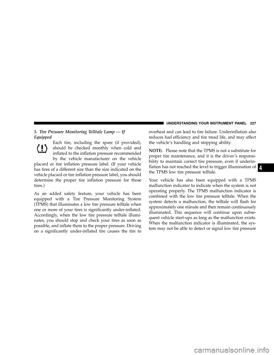
5. Tire Pressure Monitoring Telltale Lamp Ð If
Equipped
Each tire, including the spare (if provided),
should be checked monthly when cold and
inflated to the inflation pressure recommended
by the vehicle manufacturer on the vehicle
placard or tire inflation pressure label. (If your vehicle
has tires of a different size than the size indicated on the
vehicle placard or tire inflation pressure label, you should
determine the proper tire inflation pressure for those
tires.)
As an added safety feature, your vehicle has been
equipped with a Tire Pressure Monitoring System
(TPMS) that illuminates a low tire pressure telltale when
one or more of your tires is significantly under-inflated.
Accordingly, when the low tire pressure telltale illumi-
nates, you should stop and check your tires as soon as
possible, and inflate them to the proper pressure. Driving
on a significantly under-inflated tire causes the tire tooverheat and can lead to tire failure. Underinflation also
reduces fuel efficiency and tire tread life, and may affect
the vehicle's handling and stopping ability.
NOTE:Please note that the TPMS is not a substitute for
proper tire maintenance, and it is the driver 's responsi-
bility to maintain correct tire pressure, even if underin-
flation has not reached the level to trigger illumination of
the TPMS low tire pressure telltale.
Your vehicle has also been equipped with a TPMS
malfunction indicator to indicate when the system is not
operating properly. The TPMS malfunction indicator is
combined with the low tire pressure telltale. When the
system detects a malfunction, the telltale will flash for
approximately one minute and then remain continuously
illuminated. This sequence will continue upon subse-
quent vehicle start-ups as long as the malfunction exists.
When the malfunction indicator is illuminated, the sys-
tem may not be able to detect or signal low tire pressure
UNDERSTANDING YOUR INSTRUMENT PANEL 227
4
Page 231 of 531
For additional information on Tire Pressures, refer to
Section 5 Ð Starting and Operating, ªTire Inflation
Pressuresº of this manual.
6. Oil Pressure Warning Light
This light shows low engine oil pressure. The light
should turn on momentarily when the engine is
started. If the light turns on while driving, stop the
vehicle and shut off the engine as soon as possible. A
chime will sound for four minutes when this light turns
on.
Do not operate the vehicle until the cause is corrected.
This light does not show how much oil is in the engine.
The engine oil level must be checked under the hood.
7. Engine Temperature Warning Light
This light warns of an overheated engine condi-
tion. If the engine is critically hot, a continuouschime will sound for four minutes. After the chime turns
off, the engine will still be critically hot until the light
turns off.
8. Speedometer
Indicates vehicle speed.
9. Turn Signal Indicators
The arrow will flash with the exterior turn signal
when the turn signal lever is operated.
If the vehicle electronics sense that the vehicle has
traveled about one mile with the turn signals on, a
continuous chime will sound to alert you to turn the
signals off. If either indicator flashes at a rapid rate, check
for a defective outside light bulb.
10. Electronic Stability Program (ESP) Indicator Light
The malfunction lamp for the ESP is combined
with BAS. The yellow ªESP/BAS Warning
Lampº comes on when the ignition switch is
UNDERSTANDING YOUR INSTRUMENT PANEL 229
4
Page 232 of 531
turned to the ªONº position. They should go out with the
engine running. If the ªESP/BAS Warning Lampº comes
on continuously with the engine running, a malfunction
has been detected in either the ESP or the BAS system. If
this light remains on after several ignition cycles, and the
vehicle has been driven several miles at speeds greater
than 30 mph (48 km/h), see your authorized dealer as
soon as possible.
11. Brake System Warning Light
This light monitors various brake functions,
including brake fluid level and parking brake
application. If the brake light turns on, it may
indicate that the parking brake is applied, that
the brake fluid level is low, or that there is a problem with
the anti-lock brake system (if equipped).
The dual brake system provides a reserve braking capac-
ity in the event of a failure to a portion of the hydraulic
system. Failure of either half of the dual brake system isindicated by the Brake Warning Light which will turn on
when the brake fluid level in the master cylinder has
dropped below a specified level.
The light will remain on until the cause is corrected.
NOTE:The light may flash momentarily during sharp
cornering maneuvers which change fluid level condi-
tions. The vehicle should have service performed, and
the brake fluid level checked.
If brake failure is indicated, immediate repair is neces-
sary.
WARNING!
Driving a vehicle with the brake light on is danger-
ous. Part of the brake system may have failed. It will
take longer to stop the vehicle. You could have an
accident. Have the vehicle checked immediately.
230 UNDERSTANDING YOUR INSTRUMENT PANEL
Page 234 of 531
brakes. If the ABS light does not turn on when the
Ignition switch is turned to the ON position, have the
light inspected by an authorized dealer.
14. Electronic Stability Program (ESP) Indicator
Light/Traction Control System (TCS) Indicator Light
If this indicator light flashes during accelera-
tion, apply as little throttle as possible. While
driving, ease up on the accelerator. Adapt your
speed and driving to the prevailing road con-
ditions, and do not switch off the ESP, or TCS.
15. Tachometer
The red segments indicate the maximum permissible
engine revolutions per minute (RPM x 1000) for each gear
range. Before reaching the red area, ease up on the
accelerator.16. High Beam Light
This light shows that the headlights are on high
beam. Pull the turn signal lever towards the
steering wheel to switch the headlights from high or low
beam.
17. Front Fog Light Indicator Ð If Equipped
This light shows when the front fog lights are ON.
18. Seat Belt Reminder Light
When the ignition switch is first turned ON, this
light will turn on for five to eight seconds as a bulb
check. During the bulb check, if the driver's seat
belt is unbuckled, a chime will sound. After the bulb
check or when driving, if the driver's seat belt remains
unbuckled, the Seat Belt Reminder Light will illuminate
and the chime will sound. Refer to the Occupant Re-
straints section for more information.
232 UNDERSTANDING YOUR INSTRUMENT PANEL
Page 237 of 531
To reset a message display (gATE, gASCAP, noFUSE,
CHAngE OIL, LoCOOL, LoWASH), push and hold the
button until the display resets (approximately two sec-
onds).
Trip/Odometer Display Reset Button Ð Premium
Cluster
Press this button to change the display from odometer to
either of two trip odometer settings. The letter ªAº or ªBº
will appear when in the trip odometer mode. Push in and
hold the button for two seconds to reset the trip odometer
to 0 mi (km). The odometer must be in TRIP mode to
reset it.
23. Transmission Range Indicator
This display indicator shows the automatic transaxle gear
selection.
NOTE:You must apply the brakes before shifting from
PARK.24. Odometer Display Area
When the appropriate conditions exist, the following
odometer messages will display:
CHAngE OIL............... OilChange Required
CRUISE.....................Cruise Control On
door.............................Door Ajar
ESPOFF............................ ESPOff
gATE..........................Lift Gate Ajar
gASCAP.......................Fuel Cap Fault
hood*............................Hood Ajar
noFUSE..........................Fuse Fault
LoCOOL........................ LowCoolant
LoWASH.................... LowWasher Fluid
NOTE:If your vehicle is equipped with a hood switch,
in the case of hood ajar, a warning message will be
displayed in either the PRNDL/Odometer display as
ªhoodº or ªHood Ajarº in the EVIC display.
UNDERSTANDING YOUR INSTRUMENT PANEL 235
4