Page 186 of 494

The system allows the driver to select information by
pressing the following buttons on the instrument panel
switch bank:
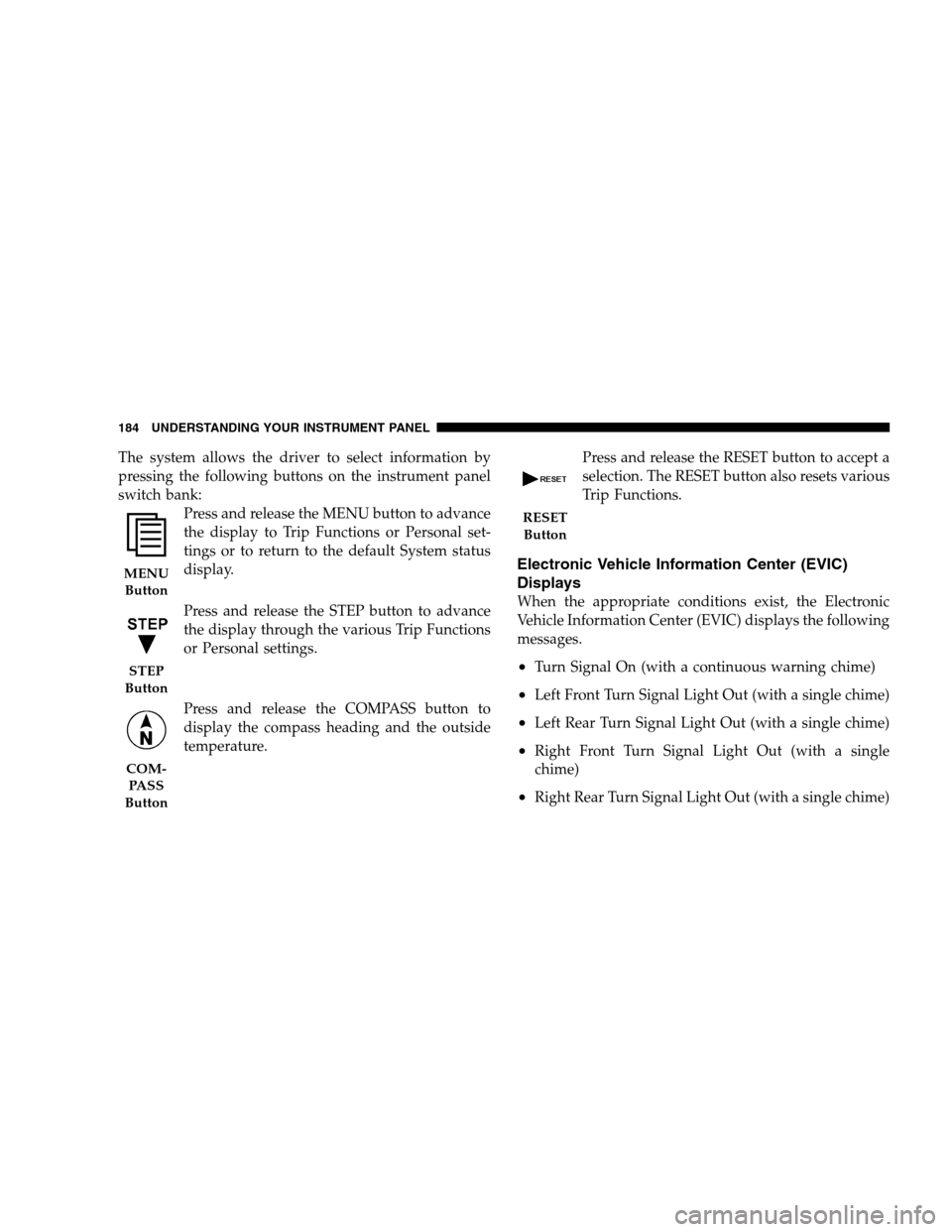
Press and release the MENU button to advance
the display to Trip Functions or Personal set-
tings or to return to the default System status
display.
Press and release the STEP button to advance
the display through the various Trip Functions
or Personal settings.
Press and release the COMPASS button to
display the compass heading and the outside
temperature.Press and release the RESET button to accept a
selection. The RESET button also resets various
Trip Functions.
Electronic Vehicle Information Center (EVIC)
Displays
When the appropriate conditions exist, the Electronic
Vehicle Information Center (EVIC) displays the following
messages.
•Turn Signal On (with a continuous warning chime)
•Left Front Turn Signal Light Out (with a single chime)
•Left Rear Turn Signal Light Out (with a single chime)
•Right Front Turn Signal Light Out (with a single
chime)
•Right Rear Turn Signal Light Out (with a single chime)
MENU
Button
STEP
Button
COM-
PA S S
Button
RESET
Button
184 UNDERSTANDING YOUR INSTRUMENT PANEL
Page 193 of 494

Auto Unlock on Exit
When ON is selected and the transaxle is in the PARK or
NEUTRAL position, all doors will unlock when the
driver’s door is opened. To make your selection, press
and hold the RESET button until ON or OFF appears.
Remote Key Unlock
When “Driver Door 1st Press” is selected, only the
driver’s door will unlock on the first press of the remote
keyless entry unlock button. When Driver Door 1st Press
is selected, you must press of the remote keyless entry
unlock button twice to unlock the passenger’s doors.
When “All Doors 1st Press” is selected, all of the doors
will unlock on the first press of the remote keyless entry
unlock button. To make your selection, press and release
the RESET button until “Driver Door 1st Press” or “All
Doors 1st Press” appears.
Sound Horn with Lock
When ON is selected, a short horn sound will occur when
the remote keyless entry LOCK button is pressed. This
feature may be selected with or without the flash lights ON,
LOCK/UNLOCK feature. To make your selection, press
and release the RESET button until ON or OFF appears.
Flash Lights with Lock
When ON is selected, the front and rear turn signals will
flash when the doors are locked or unlocked with the
remote keyless entry transmitter. This feature may be
selected with or without the Sound Horn on LOCK
feature selected. To make your selection, press and re-
lease the RESET button until ON or OFF appears.
Headlights Off Delay
When this feature is selected, the driver can choose to have
the headlights remain on for 0, 30, 60, or 90 seconds when
exiting the vehicle. To make your selection, press and hold
the RESET button until 0, 30, 60, or 90 seconds appears.
UNDERSTANDING YOUR INSTRUMENT PANEL 191
4
Page 319 of 494

Tire Pressure Monitoring Low Pressure Warnings
The Tire Pressure Monitoring Telltale Light will
illuminate in the instrument cluster and a chime
will sound when tire pressure is low in one or
more of the four active road tires. Should this occur, you
should stop as soon as possible, check the inflation
pressure of each tire on your vehicle, and inflate each tire
to the vehicle’s recommended cold placard pressure
value. Once the system receives the updated tire pres-
sures, the system will automatically update and the Tire
Pressure Monitoring Telltale Light will turn off. The
vehicle may need to be driven for up to 10 minutes above
15 mph (25 km/h) in order for the TPMS to receive this
information.
Check TPMS Warning
The Tire Pressure Monitoring Telltale Light will flash on
and off for 75 seconds and then remain on solid when a
system fault is detected. The system fault will also sound
a chime. If the ignition key is cycled, this sequence willrepeat, providing the system fault still exists. The Tire
Pressure Monitoring Telltale Light will turn off when the
fault condition no longer exists. A system fault can occur
due to any of the following:
1. Jamming due to electronic devices or driving next to
facilities emitting the same Radio Frequencies as the TPM
sensors.
2. Installing some form of aftermarket window tinting
that affects radio wave signals.
3. Lots of snow or ice around the wheels or wheel
housings.
4. Using tire chains on the vehicle.
5. Using wheels/tires not equipped with TPM sensors.
STARTING AND OPERATING 317
5
Page 348 of 494

•Trailer brakes are recommended for trailers over 1,000
lbs (450 kg) and required for trailers in excess of 2,000
lbs (907 kg).
CAUTION!
If the trailer weighs more than 1,000 lbs (450 kg)
loaded, it should have its own brakes, and they
should be of adequate capacity. Failure to do this
could lead to accelerated brake lining wear, higher
brake pedal effort, and longer stopping distances.
WARNING!
Do not connect trailer brakes to your vehicle’s hy-
draulic brake lines. It can overload your brake sys-
tem and cause it to fail. You might not have brakes
when you need them and could have an accident.
Towing any trailer will increase your stopping dis-
tance. When towing, you should allow for additional
space between your vehicle and the vehicle in front
of you. Failure to do so could result in an accident.
Towing Requirements — Trailer Lights & Wiring
Whenever you pull a trailer, regardless of the trailer size,
stoplights and turn signals on the trailer are required for
motoring safety.
Use a factory approved trailer harness and connector.
346 STARTING AND OPERATING
Page 355 of 494
HAZARD WARNING FLASHER
The flasher switch is located on the instrument panel,
below the radio. Depress the switch and both cluster
indicators and all front and rear directional signals will
flash. Depress the switch again to turn Hazard Warning
Flashers off.Do not use this emergency warning system when the
vehicle is in motion. Use it when your vehicle is disabled
and it is creating a safety hazard for other motorists.
If it is necessary to leave the vehicle to go for service, the
flasher system will continue to operate with the ignition
key removed and the vehicle locked.
NOTE:With extended use, the flasher may wear down
your battery.
IF YOUR ENGINE OVERHEATS
In any of the following situations, you can reduce the
potential for overheating by taking the appropriate ac-
tion.
•On the highways — Slow down.
•In city traffic — While stopped, put transaxle in
neutral, but do not increase engine idle speed.
Hazard Warning Flasher
WHAT TO DO IN EMERGENCIES 353
6
Page 374 of 494

▫A/C Air Filter — If Equipped............389
▫Power Steering — Fluid Check............391
▫Front Suspension Ball Joints..............391
▫Steering Linkage......................392
▫Body Lubrication.....................392
▫Windshield Wiper Blades................392
▫Windshield Washers...................393
▫Exhaust System......................393
▫Cooling System.......................394
▫Hoses And Vacuum/Vapor Harnesses.......400
▫Fuel System.........................400
▫Brake System........................400
▫Automatic Transaxle...................403▫Front And Rear Wheel Bearings...........406
▫Appearance Care And Protection From
Corrosion...........................406
▫Cleaning The Center Console Cup Holders . . . 411
�Fuses/Totally Integrated Power Module
(TIPM)..............................412
�Vehicle Storage........................417
�Replacement Bulbs......................417
�Bulb Replacement......................418
▫Headlight Bulb Replacement.............418
▫Head Light Assembly Removal —
Bulb Replacement.....................420
▫Front Turn Signal/Park Light.............422
▫FrontFogLight ......................422
372 MAINTAINING YOUR VEHICLE
Page 375 of 494
▫Tail/Stop Light, Rear Turn Signal Light,
Backup Light........................424
▫License Plate Light....................427
▫Center High-Mounted Stop Light (CHMSL) . . . 428�Fluids And Capacities...................429
�Fluids, Lubricants, And Genuine Parts........430
▫Engine.............................430
MAINTAINING YOUR VEHICLE 373
7
Page 419 of 494

VEHICLE STORAGE
If you will not be using your vehicle for more than 21
days, you may want to take steps to preserve your
battery. You may:
•Disengage the mini-fuse in the Power Distribution
Center labeled IOD (Ignition Off-Draw).
•Or, disconnect the negative cable from the battery.
REPLACEMENT BULBS
All the inside bulbs are brass or glass wedge base.
Aluminum base bulbs are not approved and should not
be used for replacement.
LIGHT BULBS — Interior Bulb Number
Front Courtesy/Reading Lights..........578/W5W
Center Courtesy/Reading Lights.........578/W5W
Visor Vanity Lights.....................A6220
Glove Box Light......................... 194LIGHT BULBS — Interior Bulb Number
Shift Indicator Light................. JKLE14140
Rear Compartment (Trunk) Light............. 579
NOTE:For lighted switches, see your dealer for replace-
ment instructions.
LIGHTS BULBS — Outside Bulb No.
Low Beam Headlight.....................9006
High Beam Headlight.....................9005
Front Park/Turn Signal/Side Marker Light. . . 3157AK
Front Fog Light.....................9145//H10
Center High Mounted Stop Light
(CHMSL)........................ W16W(921)
Rear Tail/Stop.........................3157K
Decklid Tail Light....................... T3.25
Rear Turn Signal......................3157AK
Backup Light..........................3157K
License Light........................... 168
MAINTAINING YOUR VEHICLE 417
7