2008 AUDI TT ROADSTER engine
[x] Cancel search: enginePage 238 of 316

___ C_h_ e_ c_k _in --== g'-- a_n _d_ f_il _li _n ..:::g:::..- ___________________________________________ _
& WARNING (continued)
• To reduce the danger of explosion, never connect or disconnect
charger cables while the charger is operating.
• Fast charging a battery is dangerous and should only be
attempted by a competent technician with the proper equipment.
• Battery acid that may spill during charging should be washed
off with a solution of warm water and baking soda to neutralize
the acid.
0 Note
Never use a fast charger as a booster to start the engine. This will
seriously damage sensitive electronic components , such as control
units, relays, radio, etc., as well as the battery charger.
[ i ] Tips
The vehicle battery must not be charged with a standard small
charger that plugs into the cigarette lighter or outlet .•
Windshield /headlight washer
container
Using plain water is not adequate for filling the wind
shield washer system and the headlight washer system*.
Fig . 159 Fender, left:
Windshield washer
fluid reservoir
The washer fluid container is marked with the symbol e.;. on
its cap.
- Before you check anything in the engine compartment,
always read and heed all WARNINGS=> & in "Working
in the engine compartment" on
page 220.
-Lift the filler cap tongue to add washer fluid. You can fill
the container to the top.
- Press the cap back onto the filler neck after filling the
container .
You can find the reservoir capacity in the table in~ page 291.
Use winterized windshield washer solvent during the cold season
even though the vehicle is equipped with heated washer jets. It
helps to keep your windshield clean and prevents the fluid from
freezing in the winter.
Follow the directions on the container for the correct amount to be
used.
~
Page 239 of 316

___________________________________________ C_ h_e _c_ k_ i_n _g _ a_n _d_ f_il _li _n _g __ fflllll
•
0 Note
Do not mix engine coo lant antifreeze or any other addit ives to fill up
the windshield washer reservoir. •
Vehicle care I t •
Page 245 of 316

__________________________________________________ T_ ir_e_ s_ a_ n_d _ w_ h_ e_ e_l_s __ __
•
ating the vehicle at ma ximum load , you must increase the t ire pre s
sures to those specified for maximum vehi cle load
~ & .
Bear in mind that the t ire pressure mo nitoring system can only
monitor the tire pressures you have stored . The system does not
reco gnize the load cond itio n of your vehicle.
T he effectiveness of the tire pressure monitoring system will be
impaire d if you stor e nor mal loa d pressures but then operate the
vehic le at its maximum load~&. See the
illustration~ page 242, fig. 160 for the location of the label
on driver's si de B -pillar (co lor of the ac tual label a nd exact loca tion
on the veh ic le will vary slightly).
N ote that the following tab le is accu rate at the time of going to
press and is subject to cha nge . In t he event o f discrepancies, the t ire
pressure label (on driver's side B -pillar) a lways takes precedence .
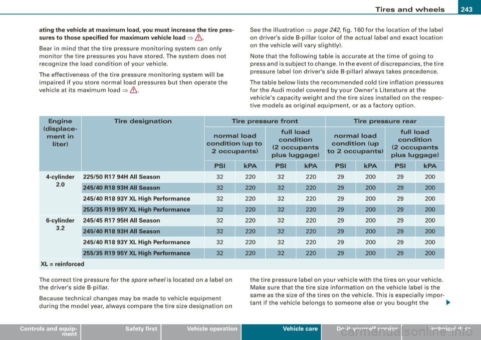
The table belo w lists t he r ecom mend ed cold tire i nflatio n pressures
for the Audi mode l covered by your Owner's Literature at the
vehic le' s capacity weigh t and the tire size s insta lled o n the respec
tive models as original equipment , or as a factory option .
Engine Tire designation
Tire pressure front II Tire pressure rear
(displace -
= " full load full load
ment in normal load
condition normal
load
condition
liter ) condition
(up to condition (up
( 2 oc cupants (2 occupants
2 o ccupants ) to 2 occupants)
plus luggage) plus luggage)
I
PSI II kPA PSI II kPA II PSI II kPA
PSI I[ kPA I
I
4-cylinder
225/50 R17 94H All Season 32 220 3 2 220 29 200 29 200
2.0
245/40 R18 93H All Season 32 220 32 220 29 200 29 200
245 /40 R18 93Y XL High Performance 32 220 32 220 29 200 29 200
255 /35 R19 95Y XL High Performance 32 220 32 220 29 200 29 200
6 -cylinder 245/45 R17 95H All Season 3 2 220 32 2 20 29 200 29 2 00
3.2
245/40 R18 93H All Season 32 220 32 220 29 200 29 200
245 /40 R18 93V XL High Performance 32 220 3 2 220 29 200 29 200
255/35 R19 95V XL High Performance 32 2 20 32 220 29 200 29 200
XL = reinforced
T he correct tire pressure for the spare wheel is located on a label on the tire p ressure label on your vehicle with the tires on your vehic le.
t he d river's s ide B -pilla r. Make sure that the tire s ize inf ormat ion on t he veh icle labe l is t he
Because technical changes may be made to vehicle equipment same as the si
ze of the tires on the vehicle. This is especially impor -
t ant if the ve hicle belongs to so meo ne else or you bought the
dur ing th e mode l year, always co mpare the tire size designa tion on
Vehicle care
I t •
.,
Page 265 of 316

_____________________________________________ W_ h_ a_t _d.....;. o_ l _d _o :....:.. n:..o:.. w.:....... ?:....:..--Jffllll
& WARNING
• Using a bumper jac k to raise the vehicle will damage the
bumper system . The jack may slip , causing injury .
• Never support your veh icle on cinder blocks , bri cks or other
obje cts. The se may not be able to support the load and could
c ause injury when they fail.
• Never start or run the engine while the vehicle is supported by
the jack .
• If you mu st work under the vehicle, always use safety stands
specifically des igned for this purpose .
• Never use the he xagonal socket in the handle of the screw
driver to loo sen or tighten the wheel bolts . •
Tire repair
App lies to vehicles: with Tire Mob ility System
General and safety pointers
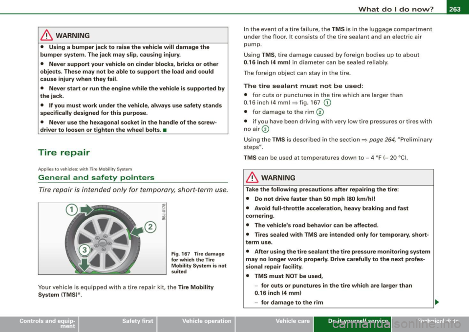
Tire repair is in tended only for te m porary, shor t- te rm use.
®
Fig . 16 7 Tire damage
for which the Tire Mobility Sy stem is not
suited
Your vehicle is equipped with a tire repai r kit, the Tire Mobil ity
System (TMS) *. I
n the event of a tire fai lure, the TMS is in the luggage compartment
u nde r th e floo r. It cons ists of the tir e sealan t and an el ectric a ir
pump .
U sing TMS, tire damage caused by foreign bodies up to about
0 .16 inch (4 mm ) in diam eter can be seale d relia bly.
T he foreign object can stay in the tire .
The tire sealant must not be used:
• for cuts or punctures in the tire which are large r than
0.16 inch (4 mm)~ fig . 167
G)
• for damage to the rim 0
• if you have been driving with very low tire pressures or tires w ith
n o air G)
Using the TMS is described in the section~ page
264, "Preliminary
steps" .
TMS can be used a t te m peratures down to -4 °F ( -20 °C).
& WARNING
Take the following precautions after repairing the tire :
• Do not drive faster than 50 mph (80 km /hi!
• Avoid full -throttle acceleration , heavy braking and fast
cornering .
• The vehicle's road behavior can be affe cted .
• Tires sealed with TMS are intended only for temporary , short
term use .
• After using the tire sealant the tire pressure monitoring system
m ay no longer work properly . Drive carefully to the next profes
s ional repair facility.
• TMS must NOT be used ,
- for cuts or punctures in the tire whi ch are larger than
0 .16 inch (4 mm )
- for damage to the rim
Vehicle care Do-it-yourself service irechnical data
Page 275 of 316

Fuses and bul bs -
------------------
Fuses and bulbs
Fuses
Replacing a fuse
A problem in the electrical system may be caused by a
blown fuse.
Fig . 178 End face o f
i n str ume nt pan el:
re m ov ing cover pla te
t o access f uses
Fig . 179 Left si de o f
engine co mpartm ent:
fu se cover
Fus e cove r on the left end face of the instrum ent
panel
- Switch off the ignition and the e lectr ica l component
affected . - Carefully pry the fuse cover off the instrument panel
using the ignition key or a screwdriver=> fig. 178.
- C heck the fuse listing on the next pages to find out w hich
fuse belongs to the component which has failed => page 274, "F use Location, Instrument Pane l le ft".
- Remove the blown fuse with the plastic clip provided .
The clip is located on the holder in the fuse box .
Replace a blown fuse (recognizable by the melted metal
str ip inside) with a fuse of the same amperage.
- Firmly snap the cover back onto the instrument panel
face.
Fuse cov er in engin e compartment
- Switch the ignition a nd the affec ted co nsumer off .
- Unlatch the fuse cover, push the two s lides forward
=> fig . 179.
- Find out which fuse belongs to the equipment which
stopped working=> page 276, "Fuse location, left side of
engine compartment".
- Remove the plastic from its retainer in the fuse box cover (left face end of the instrument pane l), place it on the
fuse in question and pull it out.
- If the fuse is burned out (recognizable by melted strips of metal), replace it with a new fuse of the same rating.
- Replace the fuse cover.
- Push the two slides to the rear=> fig. 179 . Install the fuse
cover carefully to prevent water from entering. .,
Vehicle care Do-it-yourself service irechnical data
Page 277 of 316

Fuses and bulbs -
----------------
Equipment No. Equipment
Amps
Engine relay, fuel tank control unit, Airbag Off
16 A/C system (control unit) 10
1
light, light switch (switch illumination), diagnos-10
tic connector
17 Tire pressure monitoring system (control unit) 5
18
Not used
ABS, ASR, ESP, brake light switch
5 19
Not used
3 AFS headlight (left) 5
Not used
Oil level sensor (extended maintenance interval)
(WIV), tire pressure monitoring system, switch
21 Fuel injectors (gasoline engine) 10
4 for Electronic Stability Program (ESP), AFS head-5 Wind deflector (Roadster) 30
lights (control unit), A/C system (pressure sen -23 Horn 20 sorl, backup light switch
Automatic headlight range control, AFS head-
24 Transmission (control unit) 15
5
light (right)/ manual headlight range control, 5/10
25 Heater rear window Coupe/heated rear window 30/20
halogen headlights Roadster
Control unit for CAN data transfer (gateway),
26 Driver's side power window 30
6 electromechanical steering, automatic transmis-5
27 Passenger's side power window 30
sion shift gate
28 Not used
Acoustic Park Assist, automatic dipping interior
rear view mirror, garage door opener, heatable
29 Washer pump 15
7
windshield washer nozzles, washer pump, wind 5
30 Cigarette lighter 20
deflector relay (Roadster)
31 Starter 40
8
Haldex clutch 5 32 Steering column module 5
9
Control unit Audi magnetic ride 5 33
Instrument cluster 5
Airbag control unit 5 34 Radio navigation system, radio 15
1 1 Mass airflow sensor, crankcase heating 5/10
35
Audio amplifier 30
12 Door control unit (central locking driver/passen-10
36 Engine (control unit) 10 ger)
13 Diagnostic connector 10 37 CAN (Gateway) 5
Rain sensor, automatic transmission shift gate 5 38 Not used
15 Roof
light (interior lighting) 5 39 Not used
• Do-it
-yourself service
Page 278 of 316

-L____:F_:U::..: S::: e:::. S ::::....:: a::. n :..:.::: d:....::: b:..:U :.: l.=b :.::S :..._ ____________________________________________ _
No. Equ ipm ent
40 Not used
41 Not used
42 Not used
43 Not used
44 Not used
45 Not used
46 Not used Amps
47 SDARS tuner, cell phone package, TV tuner
5
48 VDA interface 5
49 Not used
Fuse location , left side of engine
compartment
Fig . 18 1 Ill ustra tio n of
fu se h old er o n l eft s ide
of e ngine co mpart
m en t: fu se s (w ithout
fu se cov er)
Some of the equipment items listed are optional or only ava ilable on
certain model configurations .
Note th at th e fo llowi ng t able is acc urate at the t ime o f go ing to
pre ss a nd is subj ect to change. In the eve nt o f discre pancie s, the
l a bel on the ins ide of the cover a lways ta k es pre cede nce .
•
No . Equipm ent
Fu se hold er (bl ack)
1 Not used
2 Not used
3 Not used
___ ,
4 Not used
5
6
7
8
Anti-theft warning system (sensor), anti -theft
warning system (horn)
Headlamp washer system
Electric fuel pumps (supplyl/volume control
valve
Windshield w ipers
9 Heated seats (driver and passenger)
10 Lumbar support (driver and passenge r)
1 1 Not used
12 Ventilation blower
Fuse hold er (brown )
1
2
3
4
5
6
7
Fuel pump 16 -cy linder)
02 sensors (6-cylinderl
Mass airflow sensor 16 -cylinderl
02 sensors (6-cylinder) Relay coil relay volume con trol valve 14-cylin
de r)
Secondary air pump valve 16-cylinder), 02 sen
sors 14 -cylinde r)
Positioning valves pre-wired engine harness Amps
5
30
15/10
30
25
10
40 15
10
5
10
5
10
10
Page 279 of 316

_______________________________________________ F_ u_ s _ e_s _ a _ n_d _ b_ u_ l_ b_ s __ ffllll
•
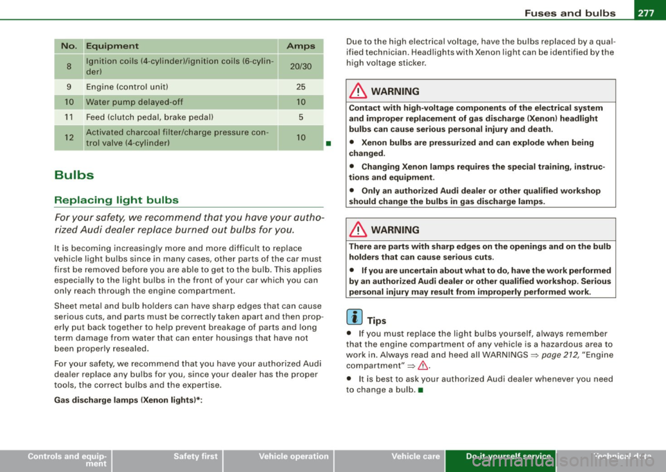
No. II Equipment Amps
8
Ignition coils (4 -cylinder)/ignition coils (6 -cylin -20/30 der)
-
9 Engine (control unit) 25
Water pump delayed-off 10
11 Feed (clutch pedal, brake pedal) 5
12
Activated charcoal filter/charge pressure con-10 trol valve (4-cylinder)
--
Bulbs
Replacing light bulbs
For your safety, we recommend that you have your autho
rized Audi dealer replace burned out bulbs for you.
It is becoming increasingly more and more difficult to replace
vehicle light bulbs since in many cases, other parts of the car must
first be removed before you are able to get to the bulb. This applies
especially to the light bulbs in the front of your car which you can
only reach through the engin e compartment .
Sheet metal and bulb holders can have sharp edges that can cause
serious cuts, and parts must be correctly taken apart and then prop
erly put back together to help prevent breakage of parts and long
term damage from wa ter that can enter housings that have not
been properly resealed.
For your safety , we recommend that you have your authorized Audi
dealer replace any bulbs for you, since your dealer has the proper
tools, the correct bulbs and the expertise.
Gas discharge lamps (Xenon lights)*:
•
Due to the high electrical voltage, have the bulbs replaced by a qual
ified technician. Headlights with Xenon light can be identified by the
high voltage sticker.
& WARNING
Contact with high-voltage components of the electrical system
and improper replacement of gas discharge (Xenon) headlight
bulbs can cause serious personal injury and death.
• Xenon bulbs are pressurized and can explode when being
changed.
• Changing Xenon lamps requires the special training, instruc
tions and equipment .
• Only an authorized Audi dealer or other qualified workshop
should change the bulbs in gas discharge lamps.
& WARNING
There are parts with sharp edges on the openings and on the bulb holders that can cause serious cuts.
• If you are uncertain about what to do, have the work performed
by an authorized Audi dealer or other qualified workshop. Serious
personal injury may result from improperly performed work.
[ i] Tips
• If you must replace the light bulbs yourself, always remember
that the engine compar tment of any vehicle is a hazardous area to
work in. Always read and heed all WARNINGS =>
page 212, "Engine
compartment"=> &.
• It is best to ask your authorized Audi dealer whenever you need
to change a bulb. •
Do-it-yourself service