2008 AUDI S5 check engine light
[x] Cancel search: check engine lightPage 233 of 294
Downloaded from www.Manualslib.com manuals search engine Checking and topping up fluids231
Controls
Safety
Driving tips
General maintenance
Self-help
Technical data
Replacing the battery
A replacement battery must have the same specifications
as the original equipment battery.Your vehicle is equipped with an intelligent power management
system to control the distribution of electrical energy ⇒page 192.
The power management function ensures that the battery is
charged much more efficiently than on vehicles without a power
management system. For this additional power to be available after
replacing the battery, we recommend that the replacement battery
used is of the same make and type as the original-equipment
battery. The battery must be encoded in the control unit for power
management. This has to be done by a qualified workshop.
A replacement battery must have the same capacity, voltage (12 V)
and current rating. It must also have the same dimensions as the
original, factory-fitted battery and have sealed caps. The battery
must comply with the standards TL 825 06 (dated December 1997 or
later) and VW 7 50 73 (August 2001 or later).
Caution
•
Make sure that the vent hose is always attached to the opening
on the side of the battery. Gases or battery acid can otherwise
escape and possibly cause damage.
•
The battery holder and clamps must always be correctly secured.
•
Before starting any work on the battery, always observe the
warnings listed under ⇒page 229, “Important safety warnings for
handling a car battery”.For the sake of the environment
Batteries contain toxic substances including sulphuric acid and
lead. They must be disposed of appropriately and must not be put
together with ordinary household waste. Make sure the battery
removed from the vehicle cannot tip over. Otherwise, sulphuric acid
could escape.
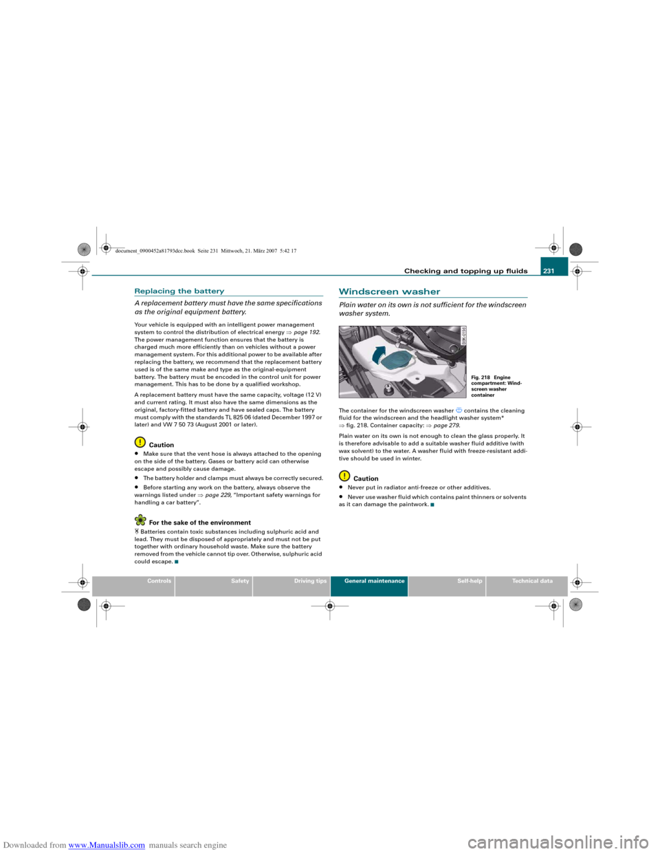
Windscreen washerPlain water on its own is not sufficient for the windscreen
washer system.The container for the windscreen washer
contains the cleaning
fluid for the windscreen and the headlight washer system*
⇒fig. 218. Container capacity: ⇒page 279.
Plain water on its own is not enough to clean the glass properly. It
is therefore advisable to add a suitable washer fluid additive (with
wax solvent) to the water. A washer fluid with freeze-resistant addi-
tive should be used in winter.
Caution
•
Never put in radiator anti-freeze or other additives.
•
Never use washer fluid which contains paint thinners or solvents
as it can damage the paintwork.
Fig. 218 Engine
compartment: Wind-
screen washer
container
document_0900452a81793dcc.book Seite 231 Mittwoch, 21. März 2007 5:42 17
Page 235 of 294
Downloaded from www.Manualslib.com manuals search engine Wheels and tyres233
Controls
Safety
Driving tips
General maintenance
Self-help
Technical data
– The tyre pressures should only be checked when the
tyres are cold. The slightly raised pressures of warm tyres
must not be reduced.
– The pressures must be altered to suit major changes in
the load being carried.
– Avoid fast cornering and hard acceleration.
– Inspect the tyres for irregular wear from time to time.Tyre pressure and vehicle loading
The tyre pressure must be adjusted according to the load the vehicle
is carrying. We recommend adhering to the tyre pressure specifica-
tions for a maximum load. The tyre inflation pressures are listed on
a sticker on the end face of the driver's door ⇒page 232, fig. 219.
However, if you prefer an extra-smooth ride and the vehicle is not
fully loaded, you can select the tyre pressure for a normal load (no
more than three people travelling in the vehicle). However, should
you wish to drive with a full load you must increase the tyre pressure
to the specified maximum.
Under-inflation or over-inflation will reduce the life of the tyres
considerably and also impair the car's handling. Correct inflation
pressures are very important, especially at high speeds. The pres-
sures should therefore be checked at least once a month and before
starting a journey.
Do not forget the spare wheel* when checking the tyre pressures.
Keep the spare tyre inflated to the highest pressure required for the
road wheels.
Driving habits
Fast cornering, heavy acceleration and hard braking (squealing
tyres) all increase tyre wear.Wheel balancing
The wheels on new vehicles are balanced. However, various factors
encountered in normal driving can cause them to become unbal-
anced, which results in steering vibration.
Unbalanced wheels should be rebalanced, as they otherwise cause
excessive wear on steering, suspension and tyres. A wheel must
also be rebalanced when a new tyre is fitted or if a tyre is repaired.
Incorrect wheel alignment
Incorrect wheel alignment causes excessive tyre wear, impairing the
safety of the vehicle. If you notice excessive tyre wear, contact your
Audi dealer.
WARNING
•
Always adapt the tyre pressure accordingly when the vehicle
load changes.
•
Under-inflated tyres flex more and can overheat at continuous
high speeds. This can cause tread separation and tyre blow-out,
which could result in an accident.For the sake of the environment
Under-inflated tyres will increase the fuel consumption.
document_0900452a81793dcc.book Seite 233 Mittwoch, 21. März 2007 5:42 17
Page 251 of 294
Downloaded from www.Manualslib.com manuals search engine Self-help249
Controls
Safety
Driving tips
General maintenance
Self-help
Technical data
– Ensure that all passengers leave the vehicle and move
away from the danger area ⇒.
– Take the tyre sealant can and the electric compressor out
of the luggage compartment ⇒page 245.
– Fix the sticker “max. 80 km/h”, which is included with the
tyre sealant can, onto the instrument cluster where the
driver will see it.
Filling the tyre
– Shake the tyre sealant can well.
– Screw the enclosed filling hose onto the sealant can as
far as it will go. This will automatically pierce the foil
sealing the can.
– Take the valve cap off the tyre valve and use the enclosed
valve insert tool to unscrew the valve insert ⇒page 248,
fig. 228.
– Place the valve insert onto a clean surface.
– Remove the sealing plug from the filling hose and insert
the hose into the tyre valve.
– Hold the tyre sealant can upside down and fill the
complete contents of the can into the tyre.
– Then disconnect the hose and screw the valve insert
firmly back into the tyre valve.
Inflating the tyre
– Screw the filling hose of the electric compressor onto the
tyre valve and plug the connector into the cigarette
lighter.– Pump the tyre up to 2.0 to 2.5 bar and monitor the pres-
sure shown on the pressure gauge.
– If the tyre pressure remains lower than the value speci-
fied above drive the vehicle approx. 10 metres forwards
or backwards, so that the sealant can spread evenly in
the tyre. If the pressure is still lower than the specifica-
tion the tyre is too badly damaged and cannot be
repaired using the tyre sealant.
Final checks
– After about 10 minutes stop to check the tyre pressure.
– If tyre pressure is less than 1.3 bar, the tyre is too badly
damaged. Do not drive on. You should obtain profes-
sional assistance.
WARNING
•
If you have a puncture in moving traffic, switch on the hazard
warning lights and place the warning triangle in a visible location.
This is for your own safety and also warns other road users.
•
Make sure your passengers wait in a safe place (for instance
behind the roadside crash barrier).
•
Please observe the manufacturers' safety notes on the
compressor and the instructions supplied with the tyre sealant
can.
•
If it was not possible to build up a tyre pressure of 2.0 bar
within 6 minutes this means that the tyre is too badly damaged.
Do not drive on.
•
Seek professional assistance if the repair of a tyre puncture is
not possible with the sealing compound.
•
If tyre pressure is less than 1.3 bar after driving about 10
minutes, the tyre is too badly damaged. Do not drive on. You
should obtain professional assistance.
document_0900452a81793dcc.book Seite 249 Mittwoch, 21. März 2007 5:42 17
Page 268 of 294
Downloaded from www.Manualslib.com manuals search engine Fuses and bulbs 266•
Incorrect handling of the high-voltage element of xenon gas-
discharge bulbs* can have potentially fatal consequences.
•
When changing bulbs, please take care not to injure yourself on
sharp edges, in particular on the headlight housing.Caution
•
Always remove the ignition key before carrying out any work on
the electrical system - danger of short circuiting!
•
Switch off the lights or parking lights before you change a bulb.
•
Take good care to avoid damaging any components.
•
Removing the lights in particular can lead to the paintwork
becoming damaged. This is another reason why we recommend
having the bulbs changed by a qualified workshop.For the sake of the environment
Please ask your specialist retailer how to dispose of used bulbs in
the proper manner.
Note
Place the parts you have removed on a soft cloth so that they do not
become scratched.•
Please check at regular intervals that all lighting (especially the
exterior lighting) on your vehicle is functioning properly. This is not
only in the interest of your own safety, but also in that of all other
road users.
•
Before changing a bulb, make sure you have the correct new
bulb.
•
Do not touch the glass part of the bulb with your bare hands, use
a cloth or paper towel instead. Otherwise, the fingerprints left on
the glass will vaporise as a result of the heat generated by the bulb,
be deposited on the reflector and impair its surface.
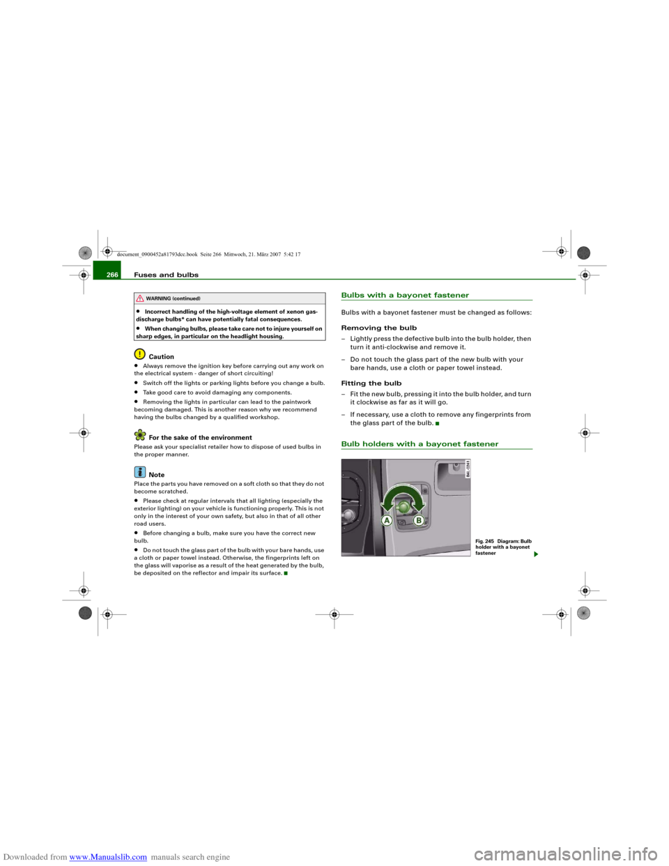
Bulbs with a bayonet fastenerBulbs with a bayonet fastener must be changed as follows:
Removing the bulb
– Lightly press the defective bulb into the bulb holder, then
turn it anti-clockwise and remove it.
– Do not touch the glass part of the new bulb with your
bare hands, use a cloth or paper towel instead.
Fitting the bulb
– Fit the new bulb, pressing it into the bulb holder, and turn
it clockwise as far as it will go.
– If necessary, use a cloth to remove any fingerprints from
the glass part of the bulb.Bulb holders with a bayonet fastener
WARNING (continued)
Fig. 245 Diagram: Bulb
holder with a bayonet
fastener
document_0900452a81793dcc.book Seite 266 Mittwoch, 21. März 2007 5:42 17
Page 270 of 294
Downloaded from www.Manualslib.com manuals search engine Fuses and bulbs 268
Installing
– Perform all of the above steps in reverse sequence.The headlight must be inserted in two guides (on the underside of
the headlight). This is the only way to ensure that the headlight is
installed in the correct position. To determine whether the headlight
is correctly installed, check that it is aligned flush with adjacent
body parts (such as the wing panel).
Do not interchange the securing screws.
Caution
Please take particular care not to damage or scratch the adjacent
parts of the body when removing or installing the headlights.Applies to vehicles: with xenon headlight bulbsChanging bulb for turn signalsThe bulb is secured in the bulb carrier with a bayonet
fastener.
– Remove the headlight ⇒page 267.
– Take off the rubber cap (small cover) and remove the bulb
carrier.
– Lightly press the defective bulb into the bulb carrier, then
turn it anti-clockwise and remove it.
– Do not touch the glass part of the new bulb with your
bare hands, use a cloth or paper towel instead.
– Fit the new bulb, pressing it into the bulb carrier, and turn
it clockwise as far as it will go.
– If necessary, use a cloth to remove any fingerprints from
the glass part of the bulb.– Insert the bulb carrier into the headlight.
Note
Ensure that the rubber cap is seated correctly so that no water can
enter the unit.Changing bulb for front fog lightsPreparations
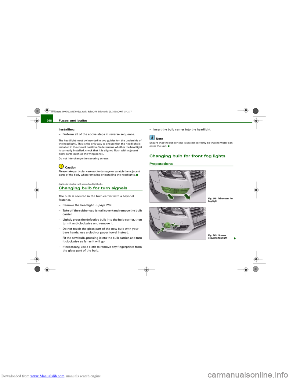
Fig. 248 Trim cover for
fog lightFig. 249 Screws
securing fog light
document_0900452a81793dcc.book Seite 268 Mittwoch, 21. März 2007 5:42 17
Page 271 of 294
Downloaded from www.Manualslib.com manuals search engine Fuses and bulbs269
Controls
Safety
Driving tips
General maintenance
Self-help
Technical data
The description for changing the bulb refers to the left fog
light; in principle the same procedure applies to the right
fog light.
– Switch off the ignition and the lights.
– Detach the trim cover ⇒page 268, fig. 248 (pull it care-
fully in the direction of the arrow).
– Remove the two securing screws ⇒page 268, fig. 249
and pull the fog light unit out of the bumper.
– Unplug the electrical connector.
CautionThe trim cover is secured to the bumper by several retaining hooks.
Do not use force when removing the trim cover to avoid damaging
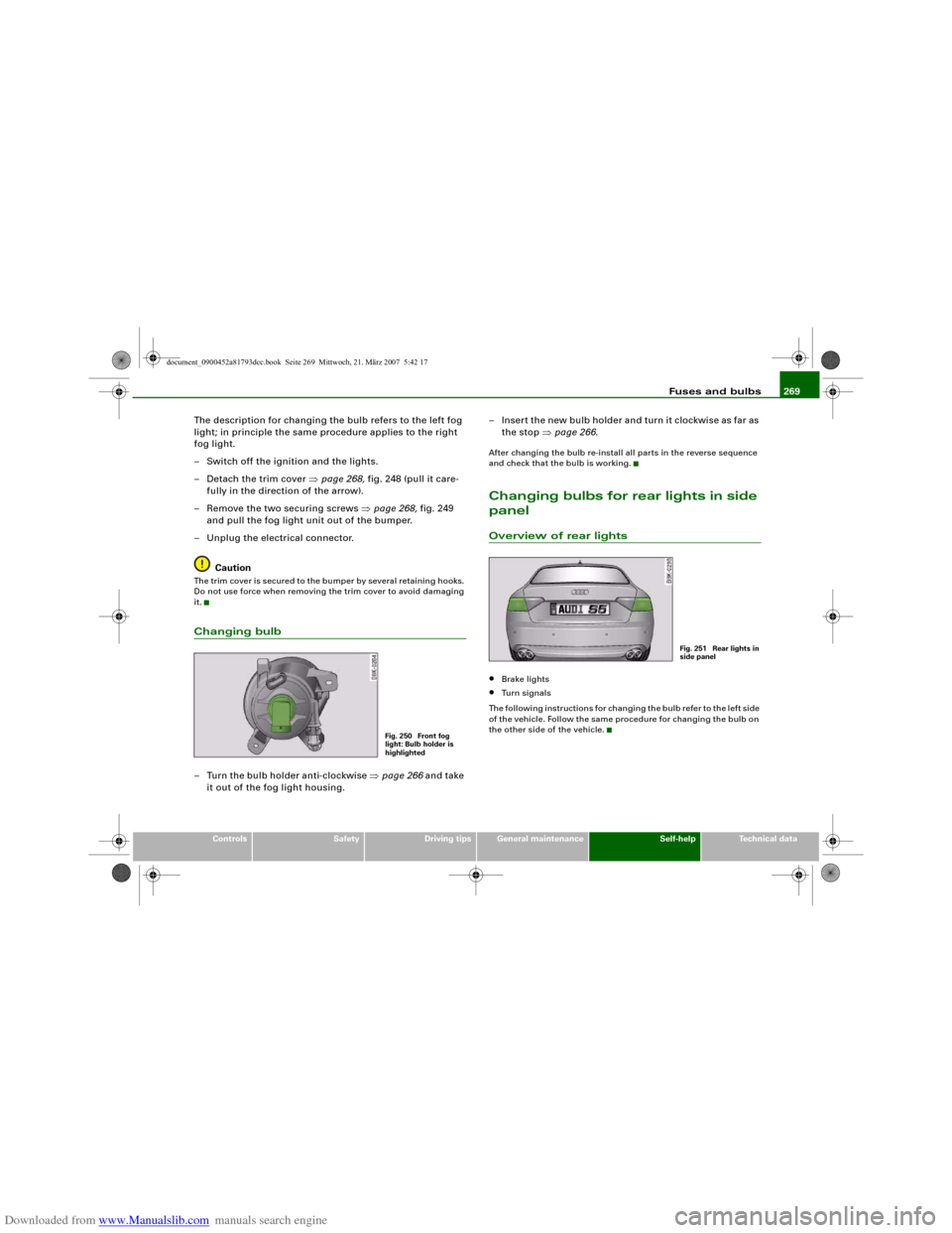
it.Changing bulb– Turn the bulb holder anti-clockwise ⇒page 266 and take
it out of the fog light housing.– Insert the new bulb holder and turn it clockwise as far as
the stop ⇒page 266.
After changing the bulb re-install all parts in the reverse sequence
and check that the bulb is working.Changing bulbs for rear lights in side
panelOverview of rear lights•
Brake lights
•
Turn signals
The following instructions for changing the bulb refer to the left side
of the vehicle. Follow the same procedure for changing the bulb on
the other side of the vehicle.
Fig. 250 Front fog
light: Bulb holder is
highlighted
Fig. 251 Rear lights in
side panel
document_0900452a81793dcc.book Seite 269 Mittwoch, 21. März 2007 5:42 17
Page 272 of 294
Downloaded from www.Manualslib.com manuals search engine Fuses and bulbs 270Removing rear light
To change the bulbs, you must remove the rear light.
Removing the light requires a certain degree of practical
skill.– Check which of the bulbs is defective.
–Open the boot lid.
– Remove the side trim.
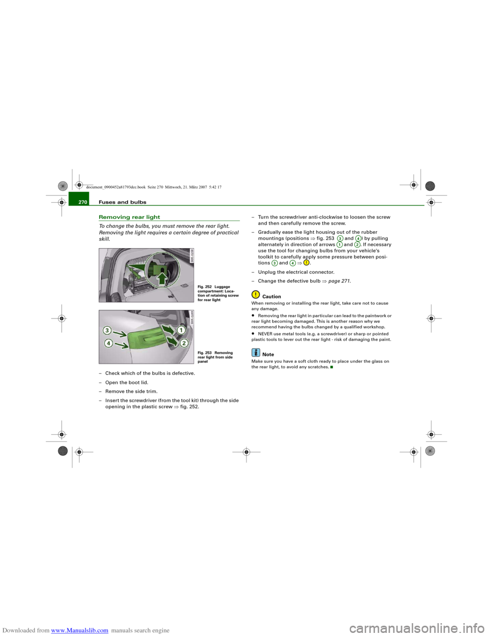
– Insert the screwdriver (from the tool kit) through the side
opening in the plastic screw ⇒fig. 252.– Turn the screwdriver anti-clockwise to loosen the screw
and then carefully remove the screw.
– Gradually ease the light housing out of the rubber
mountings (positions ⇒fig. 253 and ) by pulling
alternately in direction of arrows and . If necessary
use the tool for changing bulbs from your vehicle's
toolkit to carefully apply some pressure between posi-
tions and ⇒.
– Unplug the electrical connector.
– Change the defective bulb ⇒page 271.
Caution
When removing or installing the rear light, take care not to cause
any damage.•
Removing the rear light in particular can lead to the paintwork or
rear light becoming damaged. This is another reason why we
recommend having the bulbs changed by a qualified workshop.
•
NEVER use metal tools (e.g. a screwdriver) or sharp or pointed
plastic tools to lever out the rear light - risk of damaging the paint.Note
Make sure you have a soft cloth ready to place under the glass on
the rear light, to avoid any scratches.
Fig. 252 Luggage
compartment: Loca-
tion of retaining screw
for rear lightFig. 253 Removing
rear light from side
panel
A3
A4
A1
A2
A3
A4
document_0900452a81793dcc.book Seite 270 Mittwoch, 21. März 2007 5:42 17
Page 273 of 294
Downloaded from www.Manualslib.com manuals search engine Fuses and bulbs271
Controls
Safety
Driving tips
General maintenance
Self-help
Technical data
Changing bulbs
All bulbs can be changed easily after removing the rear
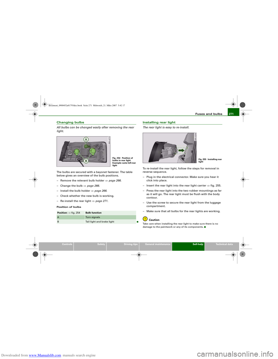
light.The bulbs are secured with a bayonet fastener. The table
below gives an overview of the bulb positions.
– Remove the relevant bulb holder ⇒page 266.
– Change the bulb ⇒page 266.
– Install the bulb holder ⇒page 266.
– Check whether the new bulb is working.
– Re-install the rear light ⇒page 271.Position of bulbs
Installing rear light
The rear light is easy to re-install.To re-install the rear light, follow the steps for removal in
reverse sequence.
– Plug in the electrical connector. Make sure you hear it
click into place.
– Insert the rear light into the rear light carrier ⇒fig. 255.
– Press the rear light into the two rubber mountings as far
as it will go. The rear light must be flush with the body
contour.
– Use the screw to secure the rear light from the luggage
compartment.
– Make sure that all bulbs for the rear lights are working.
CautionTake care when installing the rear light to make sure there is no
damage to the paintwork or any of its components.
Pos iti on: ⇒fig. 254
Bulb function
A
Tu r n s i g n a l s
B
Tail light and brake light
Fig. 254 Position of
bulbs in rear light.
Example: outer left rear
light
Fig. 255 Installing rear
light
document_0900452a81793dcc.book Seite 271 Mittwoch, 21. März 2007 5:42 17