2008 AUDI S5 diagram
[x] Cancel search: diagramPage 114 of 294
Downloaded from www.Manualslib.com manuals search engine Heating and cooling 112
Changing the battery
– Push back and remove the battery cover on the remote
control ⇒page 111, fig. 128.
– Change the battery. The diagram in the battery compart-
ment shows how the battery should be fitted. The new
battery must be of the same type as the old battery.
– Re-fit the battery cover.When it is switched on, the auxiliary heating or auxiliary ventilation
starts immediately and remains on for the period set in the menu.
The maximum running time is 60 minutes.
If you want to switch the system on again after the end of the
programmed running time, press the button .
Transmitter indicator lamp
The transmitter indicator lamp will flash accordingly to show
whether the command you sent via the remote control was
successful.
When you switch the system on by pressing the button the
indicator lamp will flash green for about 30 seconds to confirm that
the heating/ ventilation has been switched on. When you switch the
system off by pressing the button the indicator lamp will
flash red to confirm that the heating/ ventilation has been switched
off.
If the remote control is outside the transmitting range the indicator
lamp will flash red slowly. If there is a fault in the system (e.g. fuel
level is down to reserve), the indicator lamp will flash red rapidly. In
both cases the command will not be executed.
When the remote control battery is almost completely flat, the
transmitter indicator lamp will not light up and no commands will
be executed.Transmitting range
The range of the remote control transmitter is about 600 metres.
However, this can be greatly reduced by obstacles (buildings, etc.)
between the remote control transmitter and the vehicle. Hold the
aerial upright when using the remote control.
You should not normally use the remote control at a distance of less
than 3 metres from the vehicle. If you are closer than this, or if you
use the remote control inside the vehicle, this can cause signal over-
load.
For the sake of the environment
Please dispose of old batteries in the proper manner so that they do
not harm the environment.Seat heatingApplies to vehicles: with front seat heatingSeat heating for front seats
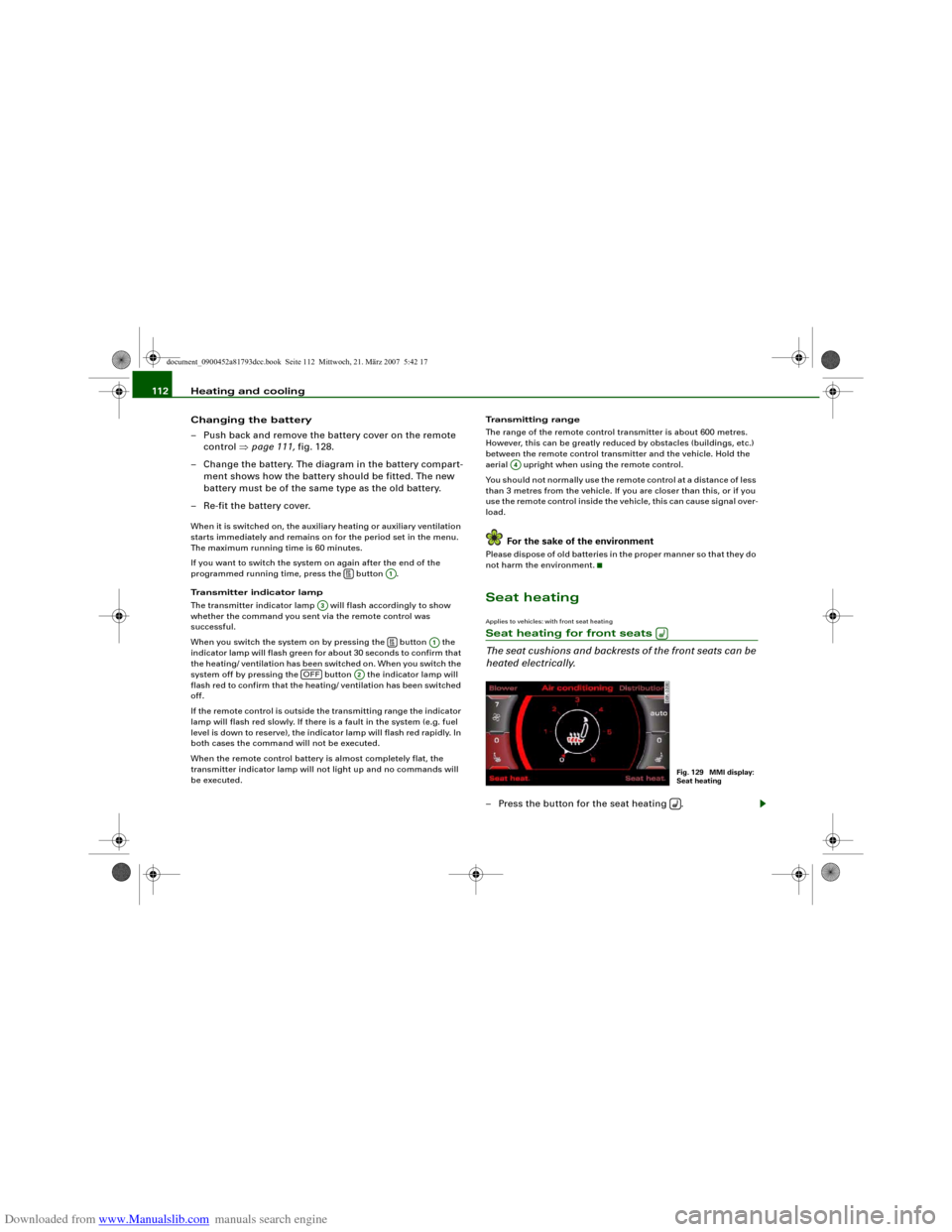
The seat cushions and backrests of the front seats can be
heated electrically.– Press the button for the seat heating .
A1
A3
A1
OFF
A2
A4
Fig. 129 MMI display:
Seat heating
document_0900452a81793dcc.book Seite 112 Mittwoch, 21. März 2007 5:42 17
Page 263 of 294
Downloaded from www.Manualslib.com manuals search engine Fuses and bulbs261
Controls
Safety
Driving tips
General maintenance
Self-help
Technical data
Fuses and bulbsFusesChanging a fuse
If a fuse has blown it must be replaced.– Identify the fuse for the failed component.
– Switch off the ignition and the component concerned.
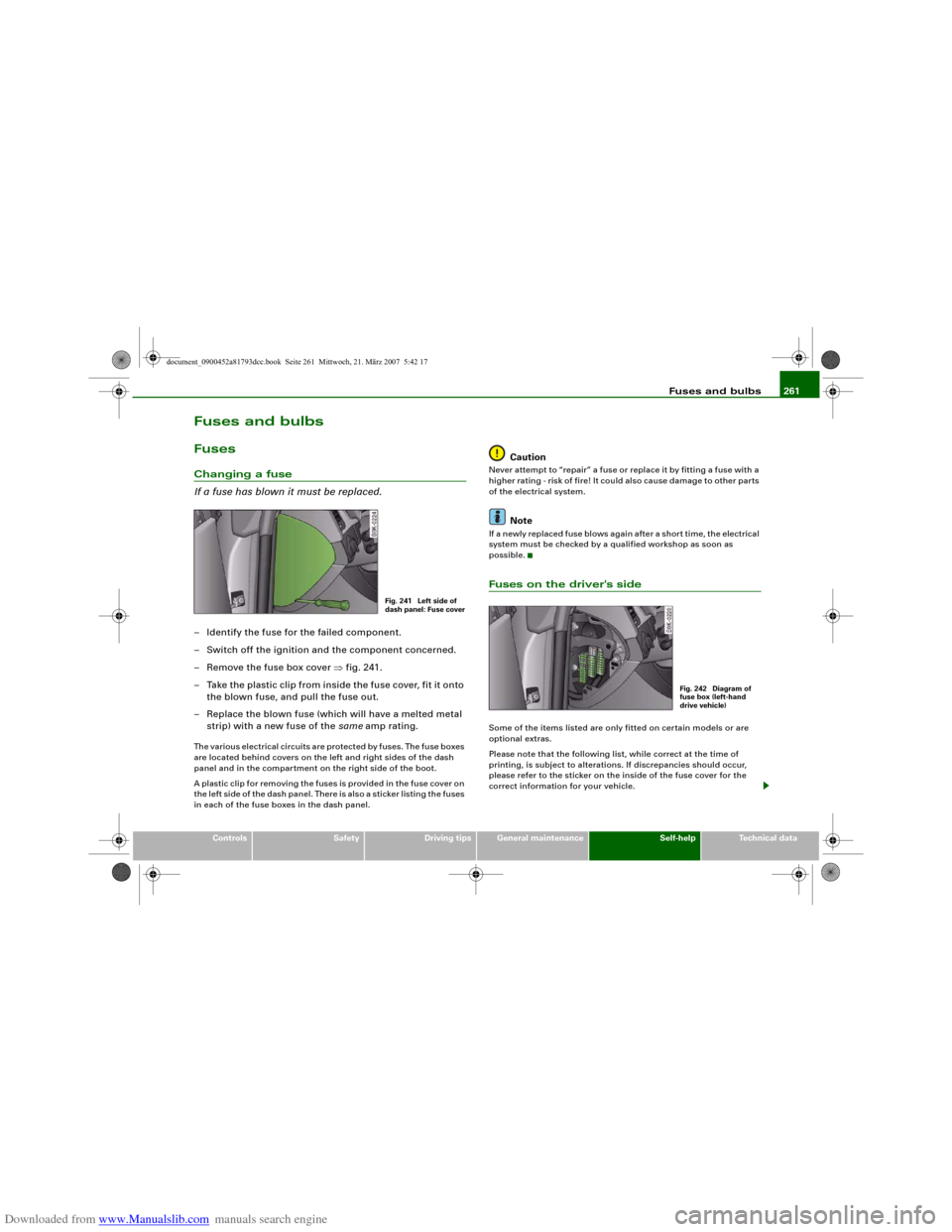
– Remove the fuse box cover ⇒fig. 241.
– Take the plastic clip from inside the fuse cover, fit it onto
the blown fuse, and pull the fuse out.
– Replace the blown fuse (which will have a melted metal
strip) with a new fuse of the same amp rating.The various electrical circuits are protected by fuses. The fuse boxes
are located behind covers on the left and right sides of the dash
panel and in the compartment on the right side of the boot.
A plastic clip for removing the fuses is provided in the fuse cover on
the left side of the dash panel. There is also a sticker listing the fuses
in each of the fuse boxes in the dash panel.
Caution
Never attempt to “repair” a fuse or replace it by fitting a fuse with a
higher rating - risk of fire! It could also cause damage to other parts
of the electrical system.
Note
If a newly replaced fuse blows again after a short time, the electrical
system must be checked by a qualified workshop as soon as
possible.Fuses on the driver's sideSome of the items listed are only fitted on certain models or are
optional extras.
Please note that the following list, while correct at the time of
printing, is subject to alterations. If discrepancies should occur,
please refer to the sticker on the inside of the fuse cover for the
correct information for your vehicle.
Fig. 241 Left side of
dash panel: Fuse cover
Fig. 242 Diagram of
fuse box (left-hand
drive vehicle)
document_0900452a81793dcc.book Seite 261 Mittwoch, 21. März 2007 5:42 17
Page 265 of 294
Downloaded from www.Manualslib.com manuals search engine Fuses and bulbs263
Controls
Safety
Driving tips
General maintenance
Self-help
Technical data
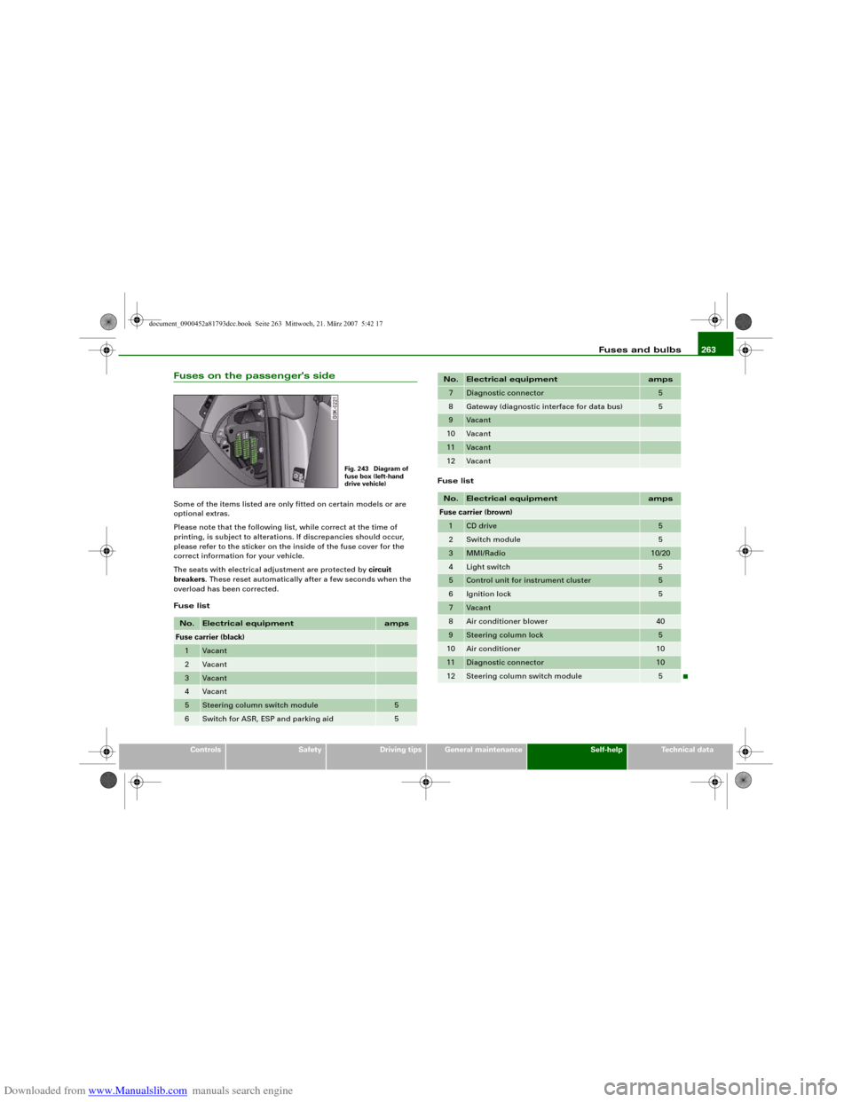
Fuses on the passenger's sideSome of the items listed are only fitted on certain models or are
optional extras.
Please note that the following list, while correct at the time of
printing, is subject to alterations. If discrepancies should occur,
please refer to the sticker on the inside of the fuse cover for the
correct information for your vehicle.
The seats with electrical adjustment are protected by circuit
breakers. These reset automatically after a few seconds when the
overload has been corrected.
Fuse listFuse listNo.
Electrical equipment
amps
Fuse carrier (black)1
Vacant
2
Vacant
3
Vacant
4
Vacant
5
Steering column switch module
5
6
Switch for ASR, ESP and parking aid
5
Fig. 243 Diagram of
fuse box (left-hand
drive vehicle)
7
Diagnostic connector
5
8
Gateway (diagnostic interface for data bus)
5
9
Vacant
10
Vacant
11
Vacant
12
Vacant
No.
Electrical equipment
amps
Fuse carrier (brown)1
CD drive
5
2
Switch module
5
3
MMI/Radio
10/20
4
Light switch
5
5
Control unit for instrument cluster
5
6
Ignition lock
5
7
Vacant
8
Air conditioner blower
40
9
Steering column lock
5
10
Air conditioner
10
11
Diagnostic connector
10
12
Steering column switch module
5
No.
Electrical equipment
amps
document_0900452a81793dcc.book Seite 263 Mittwoch, 21. März 2007 5:42 17
Page 266 of 294
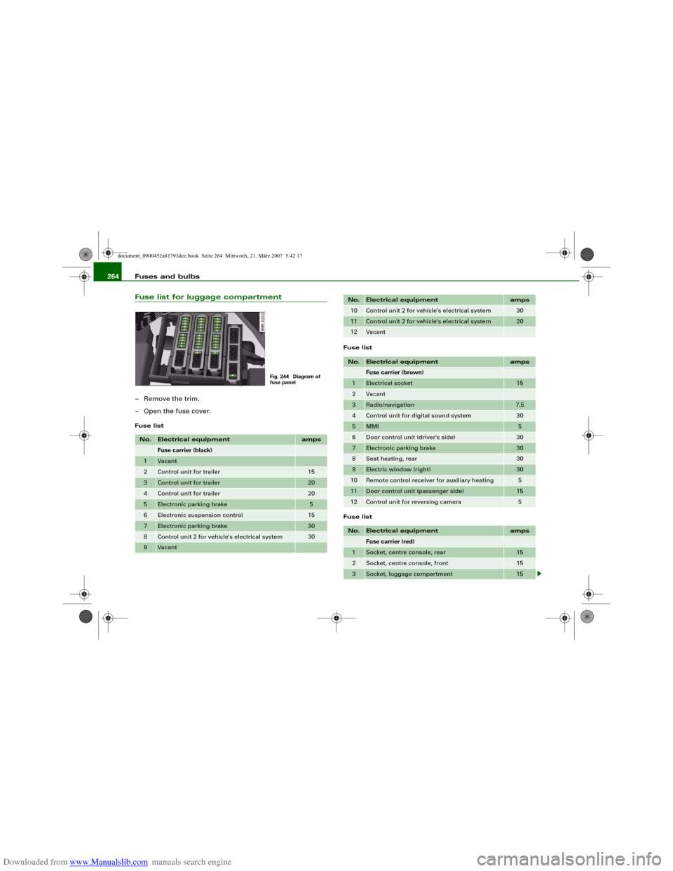
Downloaded from www.Manualslib.com manuals search engine Fuses and bulbs 264Fuse list for luggage compartment– Remove the trim.
– Open the fuse cover.Fuse listFuse list
Fuse listNo.
Electrical equipment
amps
Fuse carrier (black)
1
Vacant
2
Control unit for trailer
15
3
Control unit for trailer
20
4
Control unit for trailer
20
5
Electronic parking brake
5
6
Electronic suspension control
15
7
Electronic parking brake
30
8
Control unit 2 for vehicle's electrical system
30
9
Vacant
Fig. 244 Diagram of
fuse panel
10
Control unit 2 for vehicle's electrical system
30
11
Control unit 2 for vehicle's electrical system
20
12
Vacant
No.
Electrical equipment
amps
Fuse carrier (brown)
1
Electrical socket
15
2
Vacant
3
Radio/navigation
7.5
4
Control unit for digital sound system
30
5
MMI
5
6
Door control unit (driver's side)
30
7
Electronic parking brake
30
8
Seat heating, rear
30
9
Electric window (right)
30
10
Remote control receiver for auxiliary heating
5
11
Door control unit (passenger side)
15
12
Control unit for reversing camera
5
No.
Electrical equipment
amps
Fuse carrier (red)
1
Socket, centre console, rear
15
2
Socket, centre console, front
15
3
Socket, luggage compartment
15
No.
Electrical equipment
amps
document_0900452a81793dcc.book Seite 264 Mittwoch, 21. März 2007 5:42 17
Page 268 of 294
Downloaded from www.Manualslib.com manuals search engine Fuses and bulbs 266•
Incorrect handling of the high-voltage element of xenon gas-
discharge bulbs* can have potentially fatal consequences.
•
When changing bulbs, please take care not to injure yourself on
sharp edges, in particular on the headlight housing.Caution
•
Always remove the ignition key before carrying out any work on
the electrical system - danger of short circuiting!
•
Switch off the lights or parking lights before you change a bulb.
•
Take good care to avoid damaging any components.
•
Removing the lights in particular can lead to the paintwork
becoming damaged. This is another reason why we recommend
having the bulbs changed by a qualified workshop.For the sake of the environment
Please ask your specialist retailer how to dispose of used bulbs in
the proper manner.
Note
Place the parts you have removed on a soft cloth so that they do not
become scratched.•
Please check at regular intervals that all lighting (especially the
exterior lighting) on your vehicle is functioning properly. This is not
only in the interest of your own safety, but also in that of all other
road users.
•
Before changing a bulb, make sure you have the correct new
bulb.
•
Do not touch the glass part of the bulb with your bare hands, use
a cloth or paper towel instead. Otherwise, the fingerprints left on
the glass will vaporise as a result of the heat generated by the bulb,
be deposited on the reflector and impair its surface.
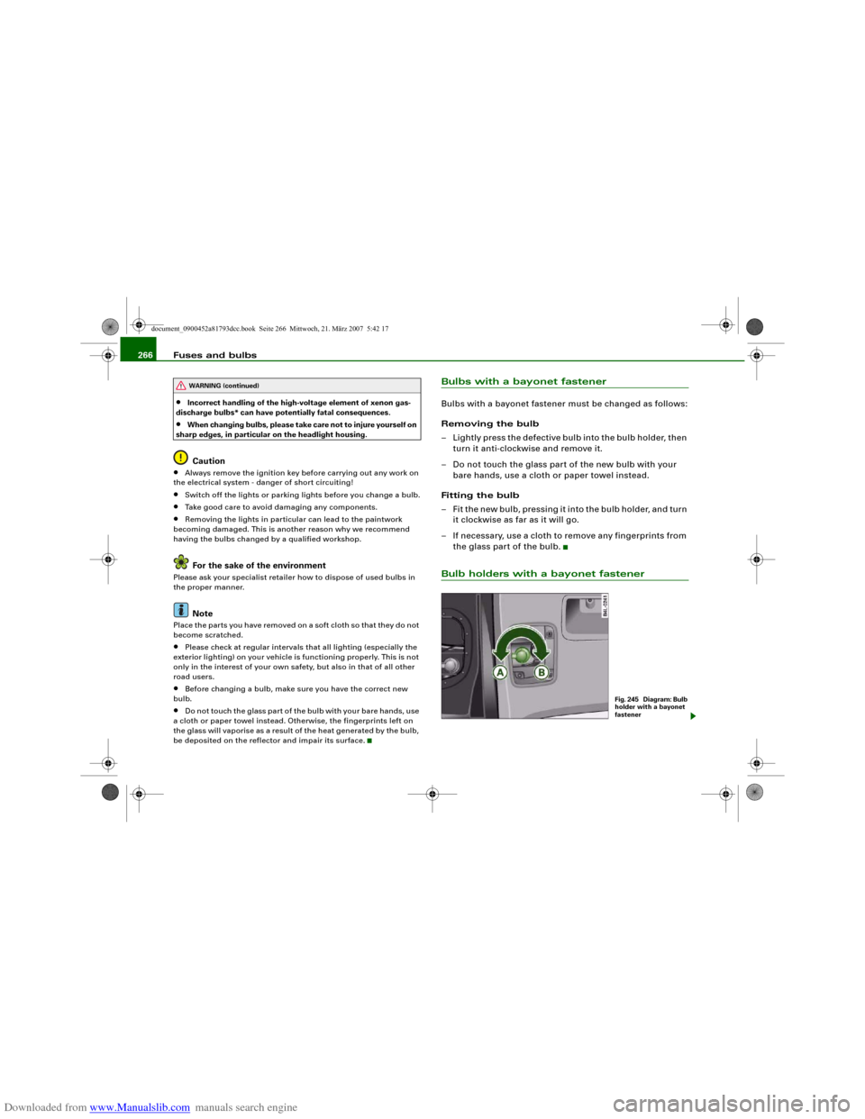
Bulbs with a bayonet fastenerBulbs with a bayonet fastener must be changed as follows:
Removing the bulb
– Lightly press the defective bulb into the bulb holder, then
turn it anti-clockwise and remove it.
– Do not touch the glass part of the new bulb with your
bare hands, use a cloth or paper towel instead.
Fitting the bulb
– Fit the new bulb, pressing it into the bulb holder, and turn
it clockwise as far as it will go.
– If necessary, use a cloth to remove any fingerprints from
the glass part of the bulb.Bulb holders with a bayonet fastener
WARNING (continued)
Fig. 245 Diagram: Bulb
holder with a bayonet
fastener
document_0900452a81793dcc.book Seite 266 Mittwoch, 21. März 2007 5:42 17