2008 AUDI A4 tow
[x] Cancel search: towPage 239 of 342
Towing a trailer237
Controls
Safety
Driving tips
General maintenance
Self-help
Technical data
– Also check the shaft section of the ball joint and its asso-
ciated mechanical parts to make sure they are clean and
undamaged.Continued ⇒page 237, “Fitting the ball joint (step 2)”.
WARNING
It is important to keep the mounting fixture clean. Otherwise the
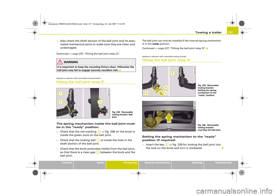
ball joint may fail to engage securely (accident risk).Applies to vehicles: with removable towing bracketFitting the ball joint (step 2)The spring mechanism inside the ball joint must
be in the "ready" position.
– Check that the red marking ⇒fig. 238 on the knob is
inside the green zone on the ball joint.
– Check that the locking ball is inside the hole in the
shaft section of the ball joint.
– Check that the knob protrudes visibly from the ball joint,
so that there is a clear gap between the knob and the
ball joint.
The ball joint can only be installed if the internal spring mechanism
is in the ready position.
Continued ⇒page 237, “Fitting the ball joint (step 3)”.Applies to vehicles: with removable towing bracketFitting the ball joint (step 3)Setting the spring mechanism to the "ready"
position (if required)
– Insert the key ⇒fig. 239 for locking the ball joint into
the lock on the knob and turn it clockwise.
Fig. 238 Removable
towing bracket: Ball
joint
A2A1A3
Fig. 239 Removable
towing bracket:
Setting the spring
mechanism to the
"ready" positionFig. 240 Removable
towing bracket:
Inserting the ball joint
A4
document_0900452a81b1b9de.book Seite 237 Donnerstag, 26. Juli 2007 9:16 09
Page 240 of 342
Towing a trailer 238
– Pull out the knob in direction , hold and turn in direc-
tion until the locking ball engages ⇒.
Inserting the ball joint
– With the spring mechanism in the “ready” position,
insert the ball joint into the mounting fixture and push it
upwards ⇒page 237, fig. 240 in the direction indicated
(arrow) ⇒. The spring mechanism should then
engage automatically with an audible click.
– Lock the ball joint by turning the key anti-clockwise.
– Take out the key and press the cover cap provided onto
the lock.Continued ⇒page 238, “Fitting the ball joint (step 4)”.
WARNING
•
If it is not possible to set the spring mechanism to the "ready"
position as described above, do not use the ball joint. Please take
your vehicle to a qualified workshop.
•
To avoid injury, keep your hands away from the knob and the
cover piece when inserting the ball joint into the mounting fixture.Note
Make sure that the knob can turn freely when the ball joint is
inserted.
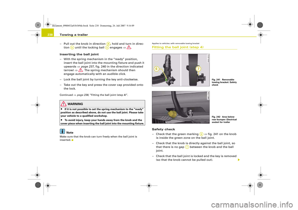
Applies to vehicles: with removable towing bracketFitting the ball joint (step 4)Safety check
– Check that the green marking ⇒fig. 241 on the knob
is inside the green zone on the ball joint.
– Check that the knob is directly against the ball joint, so
that there is no gap between the knob and the ball
joint.
– Check that the ball joint is locked and the key is removed
(so that the knob cannot be pulled out).
Aa
Ab
A5
Fig. 241 Removable
towing bracket: Safety
checkFig. 242 Area below
rear bumper: Electrical
socket for trailer
A6
A7
document_0900452a81b1b9de.book Seite 238 Donnerstag, 26. Juli 2007 9:16 09
Page 241 of 342
Towing a trailer239
Controls
Safety
Driving tips
General maintenance
Self-help
Technical data
– Check that the ball joint fits tightly in the mounting
fixture (try moving it about to check).
Electrical socket for trailer
– The cable of the towing bracket can be connected to the
socket ⇒page 238, fig. 242.If the safety check is not satisfactory, the ball joint must be fitted
again properly.
WARNING
To avoid accidents, the ball joint must meet all the safety require-
ments listed in the safety check. The towing bracket must not be
used if any one of these requirements is not met. If this is the case,
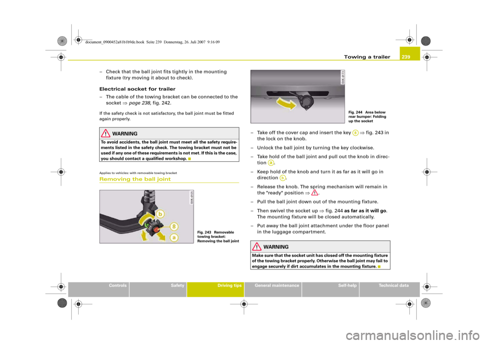
you should contact a qualified workshop.Applies to vehicles: with removable towing bracketRemoving the ball joint
– Take off the cover cap and insert the key ⇒fig. 243 in
the lock on the knob.
– Unlock the ball joint by turning the key clockwise.
– Take hold of the ball joint and pull out the knob in direc-
tion .
– Keep hold of the knob and turn it as far as it will go in
direction .
– Release the knob. The spring mechanism will remain in
the "ready" position ⇒.
– Pull the ball joint down out of the mounting fixture.
– Then swivel the socket up ⇒fig. 244 as far as it will go.
The mounting fixture will be closed automatically.
– Put away the ball joint attachment under the floor panel
in the luggage compartment.
WARNING
Make sure that the socket unit has closed off the mounting fixture
of the towing bracket properly. Otherwise the ball joint may fail to
engage securely if dirt accumulates in the mounting fixture.
Fig. 243 Removable
towing bracket:
Removing the ball joint
Fig. 244 Area below
rear bumper: Folding
up the socketA8
Aa
Ab
document_0900452a81b1b9de.book Seite 239 Donnerstag, 26. Juli 2007 9:16 09
Page 242 of 342
Towing a trailer 240Applies to vehicles: with towing bracketTowing bracket (retrofitting)
If required, the vehicle can be retrofitted with a towing
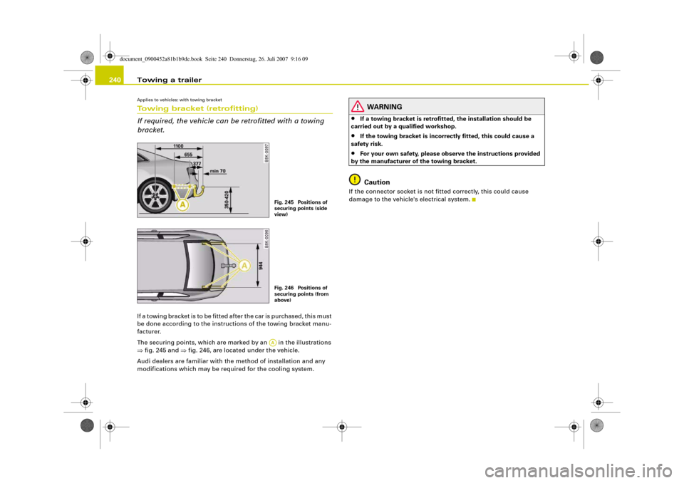
bracket.If a towing bracket is to be fitted after the car is purchased, this must
be done according to the instructions of the towing bracket manu-
facturer.
The securing points, which are marked by an in the illustrations
⇒fig. 245 and ⇒fig. 246, are located under the vehicle.
Audi dealers are familiar with the method of installation and any
modifications which may be required for the cooling system.
WARNING
•
If a towing bracket is retrofitted, the installation should be
carried out by a qualified workshop.
•
If the towing bracket is incorrectly fitted, this could cause a
safety risk.
•
For your own safety, please observe the instructions provided
by the manufacturer of the towing bracket.Caution
If the connector socket is not fitted correctly, this could cause
damage to the vehicle's electrical system.
Fig. 245 Positions of
securing points (side
view)Fig. 246 Positions of
securing points (from
above)AA
document_0900452a81b1b9de.book Seite 240 Donnerstag, 26. Juli 2007 9:16 09
Page 243 of 342
Towing a trailer241
Controls
Safety
Driving tips
General maintenance
Self-help
Technical data
document_0900452a81b1b9de.book Seite 241 Donnerstag, 26. Juli 2007 9:16 09
Page 277 of 342
Wheels and tyres275
Controls
Safety
Driving tips
General maintenance
Self-help
Technical data Furthermore, this could cause damage to your vehicle and
possibly also result in an accident.
Note
•
If you cannot continue driving even with run flat tyres please
obtain professional assistance.
•
You should obtain professional assistance if you are in any doubt
regarding the rims and tyres for your vehicle.
Applies to vehicles: with run flat tyresDriving with run flat tyres
Please remember that the vehicle's handling will be
impaired.Driving a vehicle with a deflated tyre, or with insufficient
tyre pressure, is an abnormal situation. However, since the
handling of a vehicle equipped with run flat tyres is only
slightly impaired, it is important to remember that you are
driving with a deflated tyre. If you have to make use of the
run flat system please remember the following points:
– The Electronic Stabilisation Program (ESP) must be
switched on.
–Do not exceed 80km/h ⇒.
– Anticipate the traffic situation well in advance.
– Be careful when accelerating.
– Avoid unnecessary braking and steering manoeuvres.
– Reduce speed in good time before corners and potential
hazards.
Please refer to ⇒page 274, “ When is it no longer possible to
continue driving with the help of the run flat tyres?”
Effects on handling when driving with defective tyres
If one of the front tyres is defective, your vehicle will tend to pull
slightly towards that side and braking performance will be
impaired.
A defective rear tyre will also make the vehicle pull slightly to one
side, and the braking response will again be slightly impaired.
These effects will be most noticeable when driving in a corner.
WARNING
•
When using the run flat system the changes in vehicle handling
will be noticeable when braking, in corners and during fast accel-
eration.
•
The maximum permitted speed of 80 km/h is subject to road
and weather conditions. Always observe the relevant rules and
regulations. Run flat tyres allow you to continue your journey in
the event of a loss of tyre pressure. However, the driver remains
responsible for the safety of the vehicle and for restoring the
correct tyre pressure and having defective parts replaced
⇒page 276. For these reasons you should always adjust your
driving to suit the circumstances.Caution
We recommend that you drive with great care when making use of
the run flat system. Avoid abrupt manoeuvres.
WARNING (continued)
document_0900452a81b1b9de.book Seite 275 Donnerstag, 26. Juli 2007 9:16 09
Page 286 of 342
Self-help 284If you need the tools, the Tyre Mobility System or the jack*, you will
have to open the floor panel and take out the spare wheel*
⇒page 284.
The tool kit includes:•
A hook for removing hub caps
•
Pin for mounting a wheel
•
Screwdriver with reversible blade
•
Tool for changing bulbs
•
Interchangeable socket (Torx socket for changing bulbs)
•
Crank handle for jack
•
Adapter for anti-theft wheel bolts*
•
Jack*
•
Box spanner for wheel bolts
•
Towline anchorage
Some of the parts listed are only fitted on certain models or are
optional extras.
Before stowing the jack* again, wind down the arm of the jack as far
as it will go.
WARNING
•
Do not use the hexagonal socket in the screwdriver handle to
tighten the wheel bolts. It is not possible to tighten the bolts with
the required torque – risk of accident.
•
The jack supplied by the factory is only designed for changing
wheels on this model. On no account attempt to use it for lifting
heavier vehicles or other loads – risk of injury.
•
Never start the engine when the vehicle is on the jack - risk of
accident.
•
If work has to be done under the veh i cl e , e n su re t h a t i t is sa fe l y
supported on stands designed for the purpose, otherwise there is
a risk of injury.
Applies to vehicles: with compact temporary spare wheelCompact temporary spare wheel*The spare wheel is carried in the wheel well under the
floor panel in the luggage compartment. It is only
intended for temporary use over short distances.Taking out the spare wheel
– Lift the floor panel by the plastic handle ⇒fig. 268.
– Hook the handle onto the luggage compartment weath-
erstrip.
– Turn the centre plastic knob ⇒fig. 268 anti-clockwise.
– Take out the spare wheel.
– Unhook the floor panel before closing the boot lid.
Securing the defective wheel in the spare wheel
well
– Place the wheel in the spare wheel well and secure it with
the plastic knob.
– Unhook the floor panel before closing the boot lid.
Fig. 268 Spare wheel
document_0900452a81b1b9de.book Seite 284 Donnerstag, 26. Juli 2007 9:16 09
Page 290 of 342
Self-help 288•
Seek professional assistance if the repair of a tyre puncture is
not possible with the sealing compound.
•
If tyre pressure is less than 1.3 bar after driving about 10
minutes, the tyre is too badly damaged. Do not drive on. You
should obtain professional assistance.Caution
Take special care if you have to repair a tyre on a gradient.
Note
•
Do not use the compressor for longer than 6 minutes at a time,
as it could overheat. When the compressor has cooled down, you
can use it again.
•
If tyre sealant should leak out, leave it to dry and then pull it off
like foil.
•
After carrying out a tyre repair remember to buy a new tyre
sealant can at a qualified workshop. This will ensure that the Tyre
Mobility System is operative again.
•
Please observe the relevant regulations.
Changing a wheelPreparations
Some preparations are necessary before changing a
wheel.– If you have a flat tyre, stop the car well away from moving
traffic. Choose a location that is as level as possible.– All passengers should leave the car. They should wait in
a safe place (for instance behind the roadside crash
barrier).
– Apply the parking brake to stop the vehicle moving acci-
dentally.
–Engage first gear (manual gearbox) or move selector
lever to position P (automatic gearbox).
– When towing a trailer: unhitch the trailer from your
vehicle.
– Take the tools ⇒page 283 and the spare wheel*
⇒page 284 out of the luggage compartment.
WARNING
If you have a puncture in moving traffic, switch on the hazard
warning lights and place the warning triangle in a visible location.
This is for your own safety and also warns other road users.
Caution
If you have to change the tyre on a gradient, block the wheel oppo-
site the wheel being changed by placing a stone or similar object
under it to prevent the vehicle from rolling away.
Note
Please observe the relevant regulations.How to change a wheel
Change the wheel as described below.–Pull off the hub cap. Also refer to ⇒page 289, “Hub
caps”.
WARNING (continued)
document_0900452a81b1b9de.book Seite 288 Donnerstag, 26. Juli 2007 9:16 09