Page 17 of 74

3-4
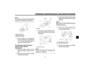
3
INSTRUMENT AND CONTROL FUNCTIONSthe “SELECT” button, and then push the
“RESET” button for at least one second.
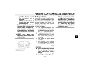
If you do not reset the fuel reserve
tripmeter manually, it will reset itself
automatically and the display will return
to the prior mode after refueling and
traveling 5 km (3mi).
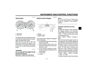
Clock mode
To set the clock:1. Push the “SELECT” button and “RESET” button together for at
least two seconds.
2. When the hour digits start flashing, push the “RESET” button to set the
hours.
3. Push the “SELECT” button, and the minute digits will start flashing.
4. Push the “RESET” button to set the minutes.
5. Push the “SELECT” button and then release it to start the clock.
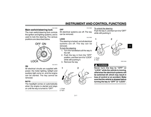
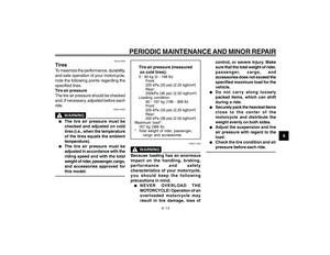
Fuel meter
With the key in the “ON” position, the
fuel meter indicates the amount of fuel
in the fuel tank. The display segments
of the fuel meter disappear towards “E”
(Empty) as the fuel level decreases. When the fuel level reaches the bottom
segment near “E”, the fuel level warning
indicator and the bottom segment will
flash. Refuel as soon as possible.
EAU12347
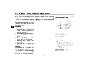
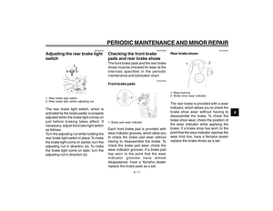
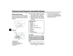
Handlebar switches1. Pass switch“
”
2. Dimmer switch “
/
”
3. Turn signal switch “
/
”
4. Horn switch “
”1
2
1. Engine stop switch “
/
”
2. Start switch ”
”
cap 3.pmd 24/1/2007, 14:37
4
Page 18 of 74

3-5
3
INSTRUMENT AND CONTROL FUNCTIONS
EAU12350
Pass switch “
”
Press this switch to flash the headlight.
EAU12400
Dimmer switch “
/
”
Set this switch to “
” for the high beam
and to “
” for the low beam.
EAU12460
Turn signal switch “
/
”
To signal a right-hand turn, push this
switch to “
”. To signal a left-hand turn,
push this switch to “
”. When released,
the switch returns to the center position.
To cancel the turn signal lights, push the
switch in after it has returned to the
center position.
EAU12500
Horn switch “
”
Press this switch to sound the horn.
EAU12660
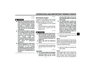
Engine stop switch “
/
”
Set this switch to “
” before starting
the engine. Set this switch to “
” to stop
the engine in case of an emergency, such
as when the motorcycle overturns or
when the throttle cable is stuck.EAU12710
Start switch “
”
Push this switch to crank the engine with
the starter.
ECA10050
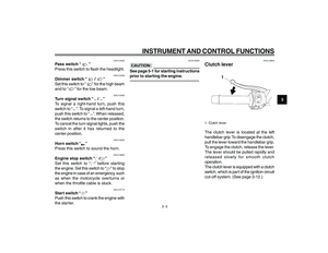
See page 5-1 for starting instructions
prior to starting the engine.
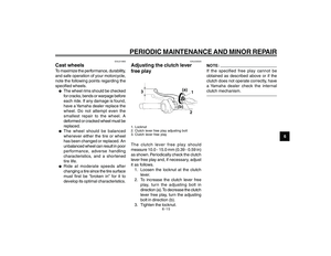
EAU12820
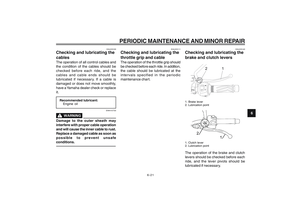
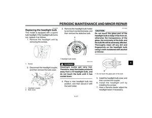
Clutch lever1. Clutch leverThe clutch lever is located at the left
handlebar grip. To disengage the clutch,
pull the lever toward the handlebar grip.
To engage the clutch, release the lever.
The lever should be pulled rapidly and
released slowly for smooth clutch
operation.
The clutch lever is equipped with a clutch
switch, which is part of the ignition circuit
cut-off system. (See page 3-12.)
cap 3.pmd 24/1/2007, 14:37
5
Page 19 of 74
3-6
3
INSTRUMENT AND CONTROL FUNCTIONS
EAU12870
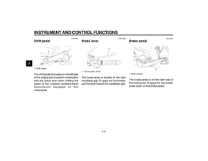
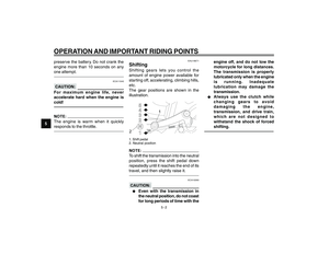
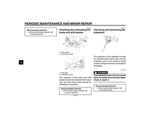
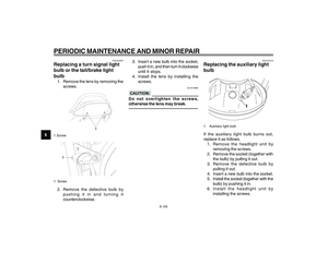
Shift pedal1. Shift pedalThe shift pedal is located on the left side
of the engine and is used in combination
with the clutch lever when shifting the
gears of the 5-speed constant-mesh
transmission equipped on this
motorcycle.
EAU12890
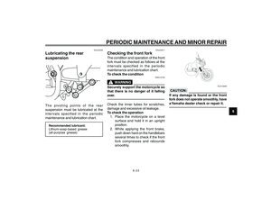
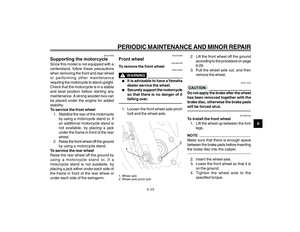
Brake lever
1
1. Front brake leverThe brake lever is located at the right
handlebar grip. To apply the front brake,
pull the lever toward the handlebar grip.
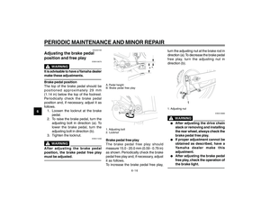
EAU12941
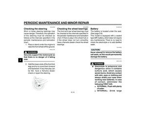
Brake pedal
1
1. Brake pedalThe brake pedal is on the right side of
the motorcycle. To apply the rear brake,
press down on the brake pedal.
cap 3.pmd24/1/2007, 14:37
6
Page 20 of 74

3-7
3
INSTRUMENT AND CONTROL FUNCTIONS
EAU13021
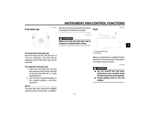
Fuel tank capTo remove the fuel tank cap
Insert the key into the lock and turn it
1/4 turn clockwise. The lock will be
released and the fuel tank cap can be
removed.
To install the fuel tank cap1. Insert the fuel tank cap into the tank opening with the key inserted
in the lock and with the “
” mark
facing forward.
2. Turn the key counterclockwise to the original position, and then
remove it.
The fuel tank cap cannot be installed
unless the key is in the lock. In addition, the key cannot be removed if the cap is
not properly installed and locked.
EWA10130
Make sure that the fuel tank cap is
properly installed before riding.
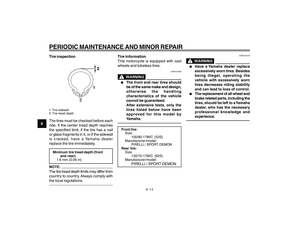
EAU13211
Fuel
1
2
1. Fuel tank filler tube
2. Fuel levelMake sure that there is sufficient fuel in
the tank. Fill the fuel tank to the bottom
of the filler tube as shown.
EWA10880
l
l l
l
l
Do not overfill the fuel tank,
otherwise it may overflow when
the fuel warms up and expands.
l
l l
l
l
Avoid spilling fuel on the hot
engine.
cap 3.pmd 24/1/2007, 14:37
7
Page 21 of 74

3-8
3
INSTRUMENT AND CONTROL FUNCTIONS
ECA10070
Immediately wipe off spilled fuel with
a clean, dry, soft cloth, since fuel may
deteriorate painted surfaces or plastic
parts.
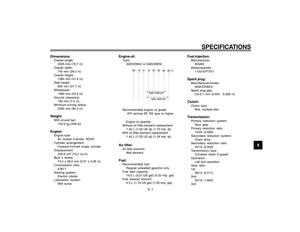
EAU33500
Recommended fuel:REGULAR UNLEADED GASOLINE ONLY
Fuel tank capacity: 19.2 L (5.07 US gal) (4.22 Imp. gal)
Fuel reserve amount (when the fuel level warning light comes on):
4.5 L (1.19 US gal) (1.00 Imp. gal)
ECA11400
Use only unleaded gasoline. The use
of leaded gasoline will cause severe
damage to internal engine parts, such
as the valves and piston rings, as well
as to the exhaust system.Your Yamaha engine has been designed
to use regular unleaded gasoline with a
research octane number of 91 or higher.
If knocking (or pinging) occurs, use a gasoline of a different brand. Use of
unleaded fuel will extend spark plug life
and reduce maintenance costs.
EAU13431
Catalytic converterThis model is equipped with a catalytic
converter in the exhaust system.
EWA10860
The exhaust system is hot after
operation. Make sure that the exhaust
system has cooled down before
doing any maintenance work.
ECA10700
The following precautions must be
observed to prevent a fire hazard or
other damages.l
l l
l
l
Use only unleaded gasoline. The
use of leaded gasoline will cause
unrepairable damage to the
catalytic converter.
l
l l
l
l
Never park the vehicle near
possible fire hazards such as
grass or other materials that
easily burn.
l
l l
l
l
Do not allow the engine to idle
too long.
cap 3.pmd 24/1/2007, 14:37
8
Page 22 of 74
3-9
3
INSTRUMENT AND CONTROL FUNCTIONS
EAU13800
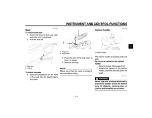
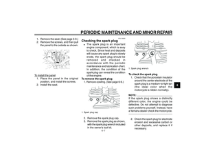
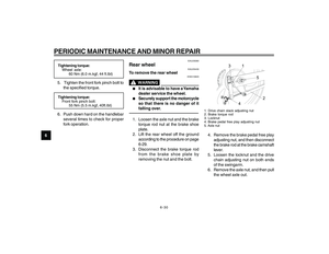
SeatTo remove the seat1. Insert the key into the seat lock, and then turn it clockwise.
2. Pull the seat off.
1
2
1. Seat lock
2. UnlockTo install the seat
1. Insert the projections on the front of the seat into the seat holders
as shown.
1. Projection
2. Seat holder2. Push the rear of the seat down tolock it in place.
3. Remove the key.Make sure that the seat is properly
secured before riding.
EAU14300
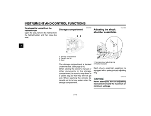
Helmet holder
1
1. Helmet holderThe helmet holder is located under the
seat.
To secure a helmet to the helmet
holder 1. Open the seat. (See page 3-9.)
2. Attach the helmet to the helmet holder, and then securely close the
seat.
EWA10160
Never ride with a helmet attached to
the helmet holder, since the helmet
may hit objects, causing loss of
control and possibly an accident.
cap 3.pmd 24/1/2007, 14:37
9
Page 23 of 74
3-10
3
INSTRUMENT AND CONTROL FUNCTIONSTo release the helmet from the
helmet holder
Open the seat, remove the helmet from
the helmet holder, and then close the
seat.
EAU37890
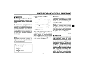
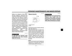
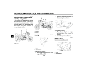
Storage compartment1. Storage compartment
2. Owner’s tool kit
3. BandThe storage compartment is located
under the seat. (See page 3-9.)
When storing the owner’s manual or
other documents in the storage
compartment, be sure to wrap them in
a plastic bag so that they will not get
wet. When washing the vehicle, be
careful not to let any water enter the
storage compar tment.
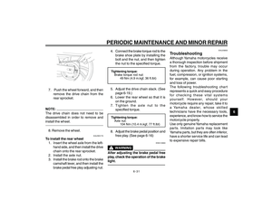
EAU14880
Adjusting the shock
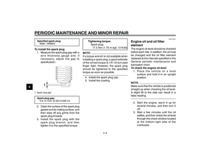
absorber assemblies1. Spring preload adjusting ring
2. Position indicatorEach shock absorber assembly is
equipped with a spring preload adjusting
ring.
ECA10100
Never attempt to turn an adjusting
mechanism beyond the maximum or
minimum settings.
cap 3.pmd24/1/2007, 14:37
10
Page 24 of 74

3-11
3
INSTRUMENT AND CONTROL FUNCTIONS
EWA10210
Always adjust both shock absorber
assemblies equally, otherwise poor
handling and loss of stability may
result.To increase the spring preload and
thereby harden the suspension, turn the
adjusting ring on each shock absorber
assembly in direction (a). To decrease
the spring preload and thereby soften
the suspension, turn the adjusting ring
on each shock absorber assembly in
direction (b).Align the appropriate notch in the
adjusting ring with the position indicator
on the shock absorber.Spring preload setting:Minimum (soft): 1
Standard:
3
Maximum (hard): 5
EAU36700
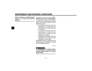
Luggage strap holders1. Luggage strap holderThere are four luggage strap holders on
the bottom of the seat. To use the strap
holders, remove the seat, unhook the
straps from the hooks, and then install
the seat with the straps hanging out from
under the seat. (See page 3-9.)
EAU15301
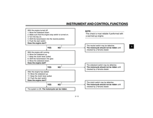
SidestandThe sidestand is located on the left side
of the frame. Raise the sidestand or lower
it with your foot while holding the
motorcycle upright.The built-in sidestand switch is part of
the ignition circuit cut-off system, which
cuts the ignition in certain situations.
(See further down for an explanation of
the ignition circuit cut-off system.)
EWA10240
The vehicle must not be ridden with
the sidestand down, or if the
sidestand cannot be properly moved
up (or does not stay up), otherwise
the sidestand could contact the
ground and distract the operator,
resulting in a possible loss of control.
Yamaha’s ignition circuit cut-off
system has been designed to assist
the operator in fulfilling the
responsibility of raising the sidestand
before starting off. Therefore, check
this system regularly as described
cap 3.pmd 24/1/2007, 14:37
11