Page 57 of 78
PERIODIC MAINTENANCE AND MINOR REPAIR
6-20
6
EAU23152
Checking and lubricating the
brake lever The operation of the brake lever should
be checked before each ride, and the
lever pivots should be lubricated if nec-
essary.
EAU23200
Checking and lubricating the
sidestand The operation of the sidestand should
be checked before each ride, and the
sidestand pivot and metal-to-metal
contact surfaces should be lubricated if
necessary.
WARNING
EWA10730
If the sidestand does not move up
and down smoothly, have a Yamahadealer check or repair it.
EAUM1650
Lubricating the swingarm piv-
ots The swingarm pivots must be lubricat-
ed at the intervals specified in the peri-
odic maintenance and lubrication chart.
Recommended lubricant:
Lithium-soap-based grease (all-pur-
pose grease)
Recommended lubricant:
Lithium-soap-based grease (all-pur-
pose grease)
Recommended lubricant:
Lithium-soap-based grease
U1P681E0.book Page 20 Tuesday, April 18, 2006 2:38 PM
Page 58 of 78

PERIODIC MAINTENANCE AND MINOR REPAIR
6-21
6
EAU42080
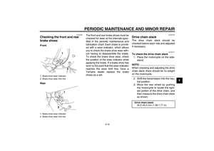
Checking the front fork The condition and operation of the front
fork must be checked as follows at the
intervals specified in the periodic main-
tenance and lubrication chart.
To check the condition
WARNING
EWA10750
Securely support the vehicle so thatthere is no danger of it falling over.
Check the inner tubes for scratches
and damage.
To check the operation
1. Place the vehicle on a level sur-
face and hold it in an upright posi-
tion.
2. While applying the front brake,
push down hard on the handlebars
several times to check if the front
fork compresses and rebounds
smoothly.
CAUTION:
ECA10590
If any damage is found or the front
fork does not operate smoothly,
have a Yamaha dealer check or re-pair it.
EAU23280
Checking the steering Worn or loose steering bearings may
cause danger. Therefore, the operation
of the steering must be checked as fol-
lows at the intervals specified in the pe-
riodic maintenance and lubrication
chart.
1. Place a stand under the engine to
raise the front wheel off the
ground.
WARNING
EWA10750
Securely support the vehicle so thatthere is no danger of it falling over.
2. Hold the lower ends of the front
fork legs and try to move them for-
ward and backward. If any free
play can be felt, have a Yamaha
dealer check or repair the steering.
U1P681E0.book Page 21 Tuesday, April 18, 2006 2:38 PM
Page 59 of 78

PERIODIC MAINTENANCE AND MINOR REPAIR
6-22
6
EAU23290
Checking the wheel bearings The front and rear wheel bearings must
be checked at the intervals specified in
the periodic maintenance and lubrica-
tion chart. If there is play in the wheel
hub or if the wheel does not turn
smoothly, have a Yamaha dealer check
the wheel bearings.
EAU40440
Battery This model is equipped with a sealed-
type (MF) battery, which does not re-
quire any maintenance. There is no
need to check the electrolyte or to add
distilled water.
WARNING
EWA10760
�
Electrolyte is poisonous and
dangerous since it contains sul-
furic acid, which causes severe
burns. Avoid any contact with
skin, eyes or clothing and al-
ways shield your eyes when
working near batteries. In case
of contact, administer the fol-
lowing FIRST AID.
EXTERNAL: Flush with plenty
of water.
INTERNAL: Drink large quan-
tities of water or milk and im-
mediately call a physician.
EYES: Flush with water for 15
minutes and seek prompt
medical attention.
�
Batteries produce explosive hy-
drogen gas. Therefore, keep
sparks, flames, cigarettes, etc.,
U1P681E0.book Page 22 Tuesday, April 18, 2006 2:38 PM
Page 60 of 78

PERIODIC MAINTENANCE AND MINOR REPAIR
6-23
6away from the battery and pro-
vide sufficient ventilation when
charging it in an enclosed
space.
�
KEEP THIS AND ALL BATTER-
IES OUT OF THE REACH OFCHILDREN.
To remove the battery
1. Remove the seat. (See page 3-7.)
2. Remove the battery cover by re-
moving the bolts.
3. Unhook the battery band, and then
pull the battery out of the battery
compartment.4. Disconnect the battery coupler.
To install the battery
1. Connect the battery coupler.
2. Place the battery in the original po-
sition, and then hook the battery
band onto the holder.
3. Install the battery cover by install-
ing the bolts.
4. Install the seat.
To charge the battery
Have a Yamaha dealer charge the bat-
tery as soon as possible if it seems to
have discharged. Keep in mind that thebattery tends to discharge more quickly
if the vehicle is equipped with optional
electrical accessories.
To store the battery
1. If the vehicle will not be used for
more than one month, remove the
battery, fully charge it, and then
place it in a cool, dry place.
2. If the battery will be stored for more
than two months, check it at least
once a month and fully charge it if
necessary.
3. Fully charge the battery before in-
stallation.
CAUTION:
ECA10630
�
Always keep the battery
charged. Storing a discharged
battery can cause permanent
battery damage.
�
To charge a sealed-type (MF)
battery, a special (constant-volt-
age) battery charger is required.
Using a conventional battery
charger will damage the battery.
If you do not have access to a
1. Bolt
2. Battery
3. Battery cover
1. Battery
2. Battery band
3. Battery coupler
U1P681E0.book Page 23 Tuesday, April 18, 2006 2:38 PM
Page 61 of 78
PERIODIC MAINTENANCE AND MINOR REPAIR
6-24
6 sealed-type (MF) battery charg-
er, have a Yamaha dealer
charge your battery.
EAU42020
Replacing the fuse The fuse is located inside the battery
coupler.
If the fuse is blown, replace it as fol-
lows.
1. Turn the key to “OFF” and turn off
all electrical circuits.
2. Disconnect the battery coupler.
3. Remove the blown fuse, and then
install a new fuse of the specified
amperage.
CAUTION:
ECA10640
Do not use a fuse of a higher amper-
age rating than recommended to
avoid causing extensive damage to
the electrical system and possibly afire.
4. Connect the battery coupler.
5. Turn the key to “ON” and turn on
the electrical circuits to check if the
devices operate.
6. If the fuse immediately blows
again, have a Yamaha dealer
check the electrical system.
1. Fuse
2. Spare fuse
Specified fuse:
10.0 A
U1P681E0.book Page 24 Tuesday, April 18, 2006 2:38 PM
Page 62 of 78

PERIODIC MAINTENANCE AND MINOR REPAIR
6-25
6
EAU24350
Supporting the motorcycle Since this model is not equipped with a
centerstand, follow these precautions
when removing the front and rear
wheel or performing other maintenance
requiring the motorcycle to stand up-
right. Check that the motorcycle is in a
stable and level position before starting
any maintenance. A strong wooden
box can be placed under the engine for
added stability.
To service the front wheel
1. Stabilize the rear of the motorcycle
by using a motorcycle stand or, if
an additional motorcycle stand is
not available, by placing a jack un-
der the frame in front of the rear
wheel.
2. Raise the front wheel off the
ground by using a motorcycle
stand.
To service the rear wheel
Raise the rear wheel off the ground by
using a motorcycle stand or, if a motor-
cycle stand is not available, by placinga jack either under each side of the
frame in front of the rear wheel or under
each side of the swingarm.
EAU24360
Front wheel
EAU39791
To remove the front wheel
WARNING
EWA10820
�
It is advisable to have a Yamaha
dealer service the wheel.
�
Securely support the motor-
cycle so that there is no dangerof it falling over.
1. Remove the guard from each front
fork leg by removing the bolts.
2. Disconnect the brake cable at the
wheel by removing the brake lever
free play adjusting nut at the brake
1. Front fork leg guard
2. Bolt
U1P681E0.book Page 25 Tuesday, April 18, 2006 2:38 PM
Page 63 of 78

PERIODIC MAINTENANCE AND MINOR REPAIR
6-26
6 camshaft lever, then remove the
cable from the brake camshaft le-
ver.
3. Loosen the axle nut.4. Lift the front wheel off the ground
according to the procedure on
page 6-25.
5. Remove the axle nut and washer.
6. Pull the wheel axle out, and then
remove the wheel.
EAU39801
To install the front wheel
1. Lift the wheel up between the fork
legs.
2. Insert the wheel axle from the
right-hand side.NOTE:Make sure that the slot in the brake
shoe plate fits over the retainer on thefork leg.3. Lower the front wheel so that it is
on the ground.
4. Install the washer and axle nut,
and then tighten the axle nut to the
specified torque.
5. Connect the brake cable to the
brake camshaft lever, and then in-
stall the brake cable free play ad-
justing nut on the brake cable.
6. Adjust the brake lever free play.
(See page 6-14.)
1. Brake cable
2. Brake camshaft lever
3. Brake lever free play adjusting nut
1. Axle nut
2. Washer
1. Wheel axle
1. Slot
2. Retainer
Tightening torque:
Axle nut:
35 Nm (3.5 m·kgf, 25 ft·lbf)
1
2
U1P681E0.book Page 26 Tuesday, April 18, 2006 2:38 PM
Page 64 of 78

PERIODIC MAINTENANCE AND MINOR REPAIR
6-27
67. While applying the front brake,
push down hard on the handlebar
several times to check for proper
fork operation.
8. Install each front fork leg guard by
installing the bolts.
EAU25080
Rear wheel
EAU39770
To remove the rear wheel
WARNING
EWA10820
�
It is advisable to have a Yamaha
dealer service the wheel.
�
Securely support the motor-
cycle so that there is no dangerof it falling over.
1. Loosen the axle nut.2. Remove the brake pedal free play
adjusting nut, and then disconnect
the brake rod from the brake cam-
shaft lever.
3. Loosen the locknut and drive chain
adjusting nut on each end of the
swingarm.
4. Lift the rear wheel off the ground
according to the procedure on
page 6-25.
5. Remove the axle nut and washer,
then pull the wheel axle out.
1. Axle nut
2. Washer
3. Drive chain slack adjusting nut
4. Locknut
1
4
3
2
1. Brake pedal free play adjusting nut
2. Brake rod
3. Brake camshaft lever
1
2
3
U1P681E0.book Page 27 Tuesday, April 18, 2006 2:38 PM


 battery charg-
er, have a Yamaha dealer
charge your battery.
EAU42020
Replacing the fuse The fuse is located inside the battery
coupler.
I")