Page 25 of 99

1
2
3
4
5
6
7
8
9
10
INSTRUMENT AND CONTROL FUNCTIONS
3-9
EAU12343
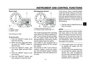
Handlebar switches
Left
1. Pass switch “1”
2. Dimmer switch “2/ 1”
3. Horn switch “o”
4. Turn signal switch “y”
5. Hazard switch “
r”
Right
1. Engine stop switch “I/B”
2. Start switch “J”
EAU12350
Pass switch “1”
Press this switch to flash the head-
light.
EAU12400
Dimmer switch “2/1”
Set this switch to “
1” for the high
beam and to “2” for the low beam.
EAU12500
Horn switch “o”
Press this switch to sound the horn.
EAU12460
Turn signal switch “y”
To signal a right-hand turn, push this
switch to “∆”. To signal a left-hand
turn, push this switch to “Ÿ”. When re-
leased, the switch returns to the cen-
ter position. To cancel the turn signal
lights, push the switch in after it has
returned to the center position.
EAU12660
Engine stop switch “I/B”
Set this switch to “I” before starting the
engine. Set this switch to “
B” to stop
the engine in case of an emergency,
such as when the motorcycle overturns
or when the throttle cable is stuck.
EAU12710
Start switch “J”
Push this switch to crank the engine
with the starter.
ECA10050CAUTION:
See page 5-1 for starting instruc-
tions prior to starting the engine.
,
MY03 01-03 ING 6-10-2005 13:52 Pagina 3-9
Page 26 of 99

INSTRUMENT AND CONTROL FUNCTIONS
3-10
1
2
3
4
5
6
7
8
9
10
EAU12733
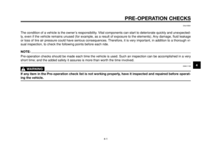
Hazard switch “r”
With the key in the “ON” or Fposition,
use this switch to turn on the hazard
lights (simultaneous flashing of all turn
signal lights).
The hazard lights are used in case of
an emergency or to warn other drivers
when your vehicle is stopped where it
might be a traffic hazard.
ECA10061CAUTION:
Do not use the hazard lights for an
extended length of time with the
engine not running, otherwise the
battery may discharge.
EAU12820
Clutch lever
1. Clutch lever
The clutch lever is located at the left
handlebar grip. To disengage the
clutch, pull the lever toward the han-
dlebar grip. To engage the clutch, re-
lease the lever. The lever should be
pulled rapidly and released slowly for
smooth clutch operation.
The clutch lever is equipped with a
clutch switch, which is part of the igni-
tion circuit cut-off system. (See page
3-19).
EAU12870
Shift pedal
1. Shift pedal
The shift pedal is located on the left
side of the engine and is used in com-
bination with the clutch lever when
shifting the gears of the 5-speed con-
stant-mesh transmission equipped on
this motorcycle.
MY03 01-03 ING 6-10-2005 13:52 Pagina 3-10
Page 27 of 99

1
2
3
4
5
6
7
8
9
10
INSTRUMENT AND CONTROL FUNCTIONS
3-11
EAU26822
Brake lever
1. Brake lever
2. Position adjusting dial
3. Arrow mark
4. Distance
The brake lever is located at the right
handlebar grip. To apply the front
brake, pull the lever toward the han-
dlebar grip.
The brake lever is equipped with a po-
sition adjusting dial. To adjust the dis-
tance between the brake lever and the
handlebar grip, turn the adjusting dial
while holding the lever pushed away
from the handlebar grip. Make sure
that the appropriate setting on the ad-
justing dial is aligned with the “˙”
mark on the brake lever.
EAU12941
Brake pedal
1. Brake pedal
The brake pedal is on the right side of
the motorcycle. To apply the rear
brake, press down on the brake pedal.
EAU13070
Fuel tank cap
1. Lock cover
2. Open
To open the fuel tank cap
Open the fuel tank cap lock cover, in-
sert the key into the lock, and then turn
it 1/4 turn clockwise. The lock will be
released and the fuel tank cap can be
opened.
MY03 01-03 ING 6-10-2005 13:52 Pagina 3-11
Page 28 of 99

INSTRUMENT AND CONTROL FUNCTIONS
3-12
1
2
3
4
5
6
7
8
9
10
To close the fuel tank cap
1. Push the fuel tank cap into posi-
tion with the key inserted in the
lock.
2. Turn the key counterclockwise to
the original position, remove it,
and then close the lock cover.
NOTE:
The fuel tank cap cannot be closed
unless the key is in the lock. In addi-
tion, the key cannot be removed if the
cap is not properly closed and locked.
EWA11090
WARNING0
Make sure that the fuel tank cap is
properly closed before riding.
EAU13210
Fuel
1. Fuel tank filler tube
2. Fuel level
Make sure that there is sufficient fuel
in the tank. Fill the fuel tank to the bot-
tom of the filler tube as shown.
EWA10880
WARNING0
• Do not overfill the fuel tank,
otherwise it may overflow when
the fuel warms up and expands.
• Avoid spilling fuel on the hot
engine.
ECA10070CAUTION:
Immediately wipe off spilled fuel
with a clean, dry, soft cloth, since
fuel may deteriorate painted sur-
faces or plastic parts.
EAU13390
Recommended fuel:
PREMIUM UNLEADED
GASOLINE ONLY
Fuel tank capacity:
15.0 L (3.96 US gal) (3.29 Imp.gal)
Fuel reserve amount (when the fuel
level warning light comes on):
4.25 L (1.12 US gal) (0.93 Imp.gal)
MY03 01-03 ING 6-10-2005 13:53 Pagina 3-12
Page 29 of 99

1
2
3
4
5
6
7
8
9
10
INSTRUMENT AND CONTROL FUNCTIONS
3-13
EAUB1300
Fuel tank breather/overflow
hose
1. Fuel tank breather/overflow hose
2. Clamp
Before operating the motorcycle:
�Check the fuel tank breather/
overflow hose connection.
�Check the fuel tank breather/
overflow hose for cracks or dam-
age, and replace it if damaged.
�Make sure that the end of the fuel
tank breather/overflow hose is not
blocked, and clean it if necessary.
�Make sure that the end of the fuel
tank breather/overflow hose is
positioned inside of the clamp.
ECA11400CAUTION:
Use only unleaded gasoline. The
use of leaded gasoline will cause
severe damage to internal engine
parts, such as the valves and piston
rings, as well as to the exhaust sys-
tem.
Your Yamaha engine has been de-
signed to use premium unleaded
gasoline with a research octane num-
ber of 95 or higher. If knocking (or
pinging) occurs, use a gasoline of a
different brand. Use of unleaded fuel
will extend spark plug life and reduce
maintenance costs.
EAU13431
Catalytic converter
This model is equipped with a catalyt-
ic converter in the exhaust system.
EWA10860
WARNING0
The exhaust system is hot after op-
eration. Make sure that the exhaust
system has cooled down before do-
ing any maintenance work.
MY03 01-03 ING 6-10-2005 13:53 Pagina 3-13
Page 30 of 99
INSTRUMENT AND CONTROL FUNCTIONS
3-14
1
2
3
4
5
6
7
8
9
10
To install the passenger seat
1. Projection
2. Seat holder
1. Insert the projection on the front
of the passenger seat into the
seat holder as shown, and then
push the back of the seat down to
lock it in place.
2. Remove the key.
EAUB1311
Seats
Passenger seat
1. Open
To remove the passenger seat
1. Insert the key into the seat lock,
and then turn it counterclockwise.
2. Pull the passenger seat off.
ECA10700CAUTION:
The following precautions must be
observed to prevent a fire hazard or
other damages.
�Use only unleaded gasoline.
The use of leaded gasoline will
cause unrepairable damage to
the catalytic converter.
�Never park the vehicle near
possible fire hazards such as
grass or other materials that
easily burn.
�Do not allow the engine to idle
too long.
MY03 01-03 ING 6-10-2005 13:53 Pagina 3-14
Page 31 of 99
1
2
3
4
5
6
7
8
9
10
INSTRUMENT AND CONTROL FUNCTIONS
3-15
1. Yamaha U-LOCK (optional)
2. Fastening strap
3. Owner’s tool kit
The passenger seat is designed to
fasten a genuine Yamaha U-LOCK to
the bottom of the seat. (Other locks
may not fit.) When fastening a U-
LOCK to the seat, securely fasten it
with the straps. When the U-LOCK is
not fastened to the seat, be sure to se-
cure the straps to prevent losing them.
Rider seat
1. Rider seat mounting bolts
To remove the rider seat
1. Remove the passenger seat.
2. Remove the bolts, and then pull
the rider seat off.
To install the rider seat
1. Projection
2. Seat holder
1. Insert the projection on the front
of the rider seat into the seat hold-
er as shown, place the seat in the
original position, and then tighten
the bolts.
2. Install the passenger seat.
NOTE:
Make sure that the seats are properly
secured before riding.
MY03 01-03 ING 6-10-2005 13:53 Pagina 3-15
Page 32 of 99

Adjust the spring preload as follows.
1. Loosen the locknut.
2. To increase the spring preload
and thereby harde")
INSTRUMENT AND CONTROL FUNCTIONS
3-16
1
2
3
4
5
6
7
8
9
10
A. Distance (spring preload)
Adjust the spring preload as follows.
1. Loosen the locknut.
2. To increase the spring preload
and thereby harden the suspen-
sion, turn the adjusting nut in di-
rection (a). To decrease the
spring preload and thereby soften
the suspension, turn the adjusting
nut in direction (b).
NOTE:
�Use the special wrench included
in the owner's tool kit to make the
adjustment.
�The spring preload setting is de-
termined by measuring distance
A, shown in the illustration. The
longer distance A is, the lower the
spring preload; the shorter dis-
tance A is, the higher the spring
preload. With each complete turn
of the adjusting nut, distance A
changes by 1.5 mm (0.059 in).
�When measuring distance A, the
rear wheel must be raised off the
ground. (See page 6-36).
EAUB1330
Adjusting the shock
absorber assembly
1. Spring preload adjusting nut
2. Locknut
(a) Increasing the spring preload
(b) Decreasing the spring preload
This shock absorber assembly is
equipped with a spring preload adjust-
ing nut.
ECA10100
WARNING0
Never attempt to turn an adjusting
mechanism beyond the maximum
or minimum settings.
MY03 01-03 ING 6-10-2005 13:53 Pagina 3-16


2. Fastening strap
3. Owner’s tool kit
The passenger seat is designed to
fasten a genuine Yamaha U-LOCK to
the")