Page 89 of 99

1
2
3
4
5
6
7
8
9
10
MOTORCYCLE CARE AND STORAGE
7-4
Long-term
Before storing your motorcycle for
several months:
1. Follow all the instructions in the
“Care” section of this chapter.
2. Fill up the fuel tank and add fuel
stabilizer (if available) to prevent
the fuel tank from rusting and the
fuel from deteriorating.
3. Perform the following steps to
protect the cylinder, piston rings,
etc. from corrosion.
a. Remove the spark plug cap
and spark plug.
b. Pour a teaspoonful of engine
oil into the spark plug bore.
c. Install the spark plug cap onto
the spark plug, and then place
the spark plug on the cylinder
head so that the electrodes
are grounded. (This will limit
sparking during the next
step.)
d. Turn the engine over several
times with the starter. (This
will coat the cylinder wall with
oil.)e. Remove the spark plug cap
from the spark plug, and then
install the spark plug and the
spark plug cap.
EWA10950
WARNING0
To prevent damage or injury from
sparking, make sure to ground the
spark plug electrodes while turning
the engine over.
4. Lubricate all control cables and
the pivoting points of all levers
and pedals as well as of the side-
stand/centerstand.
5. Check and, if necessary, correct
the tire air pressure, and then lift
the motorcycle so that both of its
wheels are off the ground. Alter-
natively, turn the wheels a little
every month in order to prevent
the tires from becoming degraded
in one spot.
6. Cover the muffler outlets with
plastic bags to prevent moisture
from entering them.
7. Remove the battery and fully
charge it. Store it in a cool, dry
place and charge it once a month.
Do not store the battery in an ex-
cessively cold or warm place [less
than 0 °C (30 °F) or more than 30
°C (90 °F)]. For more information
on storing the battery, see
page 6-31.
NOTE:
Make any necessary repairs before
storing the motorcycle.
MY03 07-10 ING 5-10-2005 17:09 Pagina 5
Page 90 of 99

SPECIFICATIONS
8-1
1
2
3
4
5
6
7
8
9
10
Engine oil:Type:
SAE10W30 or SAE10W40 or SAE15W40
or SAE20W40 or SAE20W50
Recommended engine oil grade:
API service SE, SF, SG type or higher
Engine oil quantity:
Without oil filter element replacement:
3.00 L (3.17 US qt) (2.64 Imp.qt)
With oil filter element replacement:
3.10 L (3.28 US qt) (2.72 Imp.qt)
Total amount (dry engine):
3.40 L (3.60 US qt) (2.99 Imp.qt)
Cooling system:Radiator capacity (including all routes):
1.0 L (1.05 US qt) (0.88 Imp.qt) (Radiator) +
0.25 L (0.26 US qt) (0.22 Imp.qt)
(Coolant reservoir)
Coolant reservoir capacity (up to the
maximum level mark):
0.25 L (0.26 US qt) (0.22 Imp.qt)
From low to full level:
0.15 L (0.16 US qt) (0.13 Imp.qt)
Air filter:Air filter element:
Oil-coated paper element
Fuel:Recommended fuel:
Premium unleaded gasoline only
Fuel tank capacity:
15.0 L (3.96 US gal) (3.30 Imp.gal)
Fuel reserve amount:
4.25 L (1.12 US gal) (0.93 Imp.gal)
Fuel injection:Manufacturer:
DENSO
Model:
297500-0390
Spark plug:Manufacturer/model:NGK/CR7EGap:
0.7-0.8 mm (0.028-0.032 in)
Clutch:Clutch type:
Wet, multiple-disc
Transmission:Primary reduction system:
Spur gear
Primary reduction ratio:
75/36 (2.083)
Secondary reduction system:
Chain drive
Secondary reduction ratio:
47/15 (3.133)
Transmission type:
Constant mesh 5-speed
Dimensions:Overall length:
2070 mm (81.49 in)
Overall width:
860 mm (33.85 in)
Overall height:
1115 mm (43.89 in)
Seat height:
805 mm (31.69 in)
Wheelbase:
1420 mm (55.90 in)
Ground clearance:
200 mm (7.87 in)
Minimum turning radius:
2225 mm (87.59 in)
Basic weight:With oil and fuel:
192 kg (423 lb)
195.2 kg (429 lb) (EU3 version)
Engine:Engine type:
Liquid cooled 4-stroke, SOHC
Cylinder arrangement:
Forward-inclined single cylinder
Displacement:
660.0 cm
3(40.27 cu.in)
Bore x stroke:
100.0 x 84.0 mm (3.94 x 3.31 in)
Compression ratio:
10.00 : 1
Starting system:
Electric starter
Lubrication system:
Dry sump
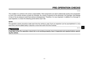
-20-10 0 1020304050°C
SAE 10W-30
SAE 10W-40
SAE 20W-40
SAE 20W-50
SAE 15W-40
Page 91 of 99

2
nd:
26/16 (1.625)
3
rd:
23/20 (1.150)
4
th:
20/22 (0.909)
5
th:
20/26 (0.769)
Chassis:
Frame ty")
1
2
3
4
5
6
7
8
9
10
SPECIFICATIONS
8-2
Operation:
Left foot operation
Gear ratio:
1
st:
30/12 (2.500)
2
nd:
26/16 (1.625)
3
rd:
23/20 (1.150)
4
th:
20/22 (0.909)
5
th:
20/26 (0.769)
Chassis:
Frame type:
Truss diamond
Caster angle:
26°
Trail:
97.0 mm (3.81 in)
Front tire:
Type:
Tubeless
Size:
120/70-ZR17M/C (58W),
120/70-R17M/C (58H)
Manufacturer/model:
DUNLOP D270F
PIRELLI SCORPION SYNC
Rear tire:
Type:
Tubeless
Size:
160/60-ZR17M/C (69W),
160/60-R17M/C (69H)Manufacturer/model:
DUNLOP D270
PIRELLI SCORPION SYNC
Load:
Maximum load:
186 kg (410 lb)
(Total weight of rider, passenger, cargo
and accessories)
Tire air pressure
(measured on cold tires):
Load:
Up to 90 kg (0-198 lb)
Front:
210 kPa (30 psi) (2.1 kgf/cm
3)
Rear:
230 kPa (33 psi) (2.3 kgf/cm
3)
Load:
90-186 kg (198-410 lb)
Front:
230 kPa (33 psi) (2.3 kgf/cm
3)
Rear:
250 kPa (36 psi) (2.5 kgf/cm
3)
High-speed riding:
Front:
210 kPa (30 psi) (2.1 kgf/cm
3)
Rear:
230 kPa (33 psi) (2.3 kgf/cm
3)
Front wheel:
Type:
Cast wheel
Rim size:
17M/C x MT3.50
Rear wheel:
Type:
Cast wheel
Rim size:
17M/C x MT5.00
Front brake:
Type:
Dual disc brake
Operation:
Right hand
Fluid:
DOT 4
Rear brake:
Type:
Single disc brake
Operation:
Right foot
Fluid:
DOT 4
Front suspension:
Type:
Telescopic fork
Spring/damper type:
Coil spring/oil damper
Wheel travel:
130 mm (5.12 in)
Rear suspension:
Type:
Swingarm
Spring/damper type:
Coil spring/gas-oil damper,
spring preload adjustable
Wheel travel:
120.0 mm (4.72 in)
MY03 07-10 ING 5-10-2005 17:09 Pagina 7
Page 92 of 99
SPECIFICATIONS
8-3
1
2
3
4
5
6
7
8
9
10
Electrical system:
Ignition system:
Transistorized coil ignition (digital)
Charging system:
A.C. magneto
Battery:
Model:
GT9B-4
Voltage, capacity:
12 V, 8 Ah
Headlight:
Bulb type:
Halogen bulb
Bulb voltage, wattage x quantity:
Headlight:
12 V, 55 W/60 W x 1
Auxiliary light:
12 V, 3 W x 1
Tail/brake light:
12 V, 5 W/21 W x 1
Front turn signal light:
12 V, 10 W x 2
Rear turn signal light:
12 V, 10 W x 2
Meter lighting:
LED (backlight)
Neutral indicator light:
LED
Turn signal indicator light:
LED
High beam indicator light:
LED
Fuel level warning light:
LEDCoolant temperature warning light:
LED
Engine trouble warning light:
LED
Immobilizer system indicator light:
LED
Fuses:Main fuse:
30 A
Headlight fuse:
20 A
Signaling system fuse:
10 A
Ignition fuse:
10 A
Parking lighting fuse:
10 A
Radiator fan fuse:
7.5 A
Fuel injection system fuse:
10 A
Backup fuse (for odometer, clock and
immobilizer):
10 A
MY03 07-10 ING 5-10-2005 17:09 Pagina 8
Page 93 of 99

1
2
3
4
5
6
7
8
9
10
CONSUMER INFORMATION
9-1
EAU26351
Identification numbers
Record the key identification number,
vehicle identification number and
model label information in the spaces
provided below for assistance when
ordering spare parts from a Yamaha
dealer or for reference in case the ve-
hicle is stolen.
KEY IDENTIFICATION NUMBER:
VEHICLE IDENTIFICATION NUMBER:
MODEL LABEL INFORMATION:
å
ç
EAU26381
Key identification number
1. Key identification number
2. Code re-registering key (red bow)
3. Standard keys (black bow)
The key identification number is
stamped into the key tag.
Record this number in the space pro-
vided and use it for reference when or-
dering a new key.
EAU26400
Vehicle identification number
1. Vehicle identification number
The vehicle identification number is
stamped into the steering head pipe.
Record this number in the space pro-
vided.
NOTE:
The vehicle identification number is
used to identify your motorcycle and
may be used to register your motorcy-
cle with the licensing authority in your
area
MY03 07-10 ING 5-10-2005 17:09 Pagina 1
Page 94 of 99
CONSUMER INFORMATION
9-2
1
2
3
4
5
6
7
8
9
10
EAU26520
Model label
1. Model label
The model label is affixed to the frame
under the passenger seat. (See page
3-14.) Record the information on this
label in the space provided. This infor-
mation will be needed when ordering
spare parts from a Yamaha dealer.
MY03 07-10 ING 5-10-2005 17:09 Pagina 2
Page 95 of 99
..........")
1
2
3
4
5
6
7
8
9
10
INDEX
A
Air filter element, cleaning the
check hoses ..................................6-13
Air filter element, replacing ..............6-13
Anti-theft alarm (optional)...................3-8
Auxiliary light bulb, replacing ...........6-34
B
Battery ..............................................6-29
To access the battery....................6-29
To charge the battery ....................6-30
To store the battery .......................6-31
Brake and clutch levers,
checking and lubricating ...............6-26
Brake fluid ........................................6-22
Changing ......................................6-22
Checking fluid level.......................6-21
Brake lever .......................................3-11
Brake pads, checking.......................6-20
Brake pedal ......................................3-11
Lubricating ....................................6-26
C
Cables, checking and lubricating .....6-25
Care and storage ...............................7-1
Cast wheels......................................6-19
Catalytic converter ...........................3-13
Checking and lubricating the
brake and clutch levers.................6-26
Checking and lubricating the
brake pedal ...................................6-26Checking and lubricating the
cables ...........................................6-25
Checking and lubricating the
sidestand ......................................6-27
Checking and lubricating the
throttle grip and cable ...................6-25
Checking the sidestand switch.........3-20
Clock mode ........................................3-7
Clutch lever ......................................3-10
Clutch lever free play, adjusting .......6-19
Consumer information ........................9-1
Controls and instruments ...................2-3
Function ..........................................3-1
Coolant .............................................6-12
Coolant temperature warning light .....3-4
D
Description .........................................2-1
Controls and instrument .................2-3
Left view..........................................2-1
Right view .......................................2-2
Dimmer switch....................................3-9
Drive chain, cleaning and
lubricating .....................................6-24
Drive chain slack ..............................6-23
Adjusting .......................................6-23
Checking .......................................6-23
E
Engine break-in ..................................5-3
Engine idling speed, adjusting .........6-14
Engine oil and oil filter element ..........6-8Engine oil filter element....................6-10
Engine stop switch .............................3-9
Engine trouble warning light...............3-4
F
Front fork, checking .........................6-27
Front wheel ......................................6-37
Installing........................................6-37
Removing......................................6-37
Fuel ..................................................3-12
Fuel consumption, tips for reducing ...5-3
Fuel level warning light ......................3-4
Fuel tank breather/overflow hose.....3-13
Fuel tank cap ....................................3-11
Fuses, replacing ...............................6-31
H
Handlebar switches ............................3-9
Dimmer switch ................................3-9
Engine stop switch..........................3-9
Hazard switch ...............................3-10
Horn switch .....................................3-9
Pass switch .....................................3-9
Start switch .....................................3-9
Turn signal switch ...........................3-9
Headlight bulb, replacing .................6-33
High beam indicator light ...................3-4
Horn switch ........................................3-9
I
Identification numbers ........................9-1
Idling speed, adjusting .....................6-14
Ignition circuit cut-off system............3-19
MY03 07-10 ING 5-10-2005 17:09 Pagina 1
Page 96 of 99

INDEX
1
2
3
4
5
6
7
8
9
10
Checking operation procedure .....3-20
Immobilizer system ............................3-1
Immobilizer system indicator light ......3-3
Indicator and warning lights ...............3-4
Coolant temperature warning
light .................................................3-4
Engine trouble warning light ...........3-4
Fuel level warning light ...................3-4
High beam indicator light ................3-4
Immobilizer system indicator light...3-3
Neutral indicator light ......................3-4
Turn signal indicator light................3-4
Indicator lights brightness
control mode ...................................3-8
Instruments ........................................2-3
Instrument and control functions ........3-1
K
Key identification number...................9-1
Keys ...................................................3-1
L
License plate light bulb, replacing....6-36
Lubricating the brake and
clutch levers ..................................6-26
Lubricating the brake pedal..............6-26
Lubricating the cables ......................6-25
Lubricating the drive chain ...............6-24
Lubricating the sidestand .................6-27
Lubricating the throttle grip and
cable .............................................6-25M
Main switch/steering lock ...................3-2
Model label .........................................9-2
Multi-function meter unit.....................3-5
Clock mode .....................................3-7
Indicator lights brightness
control mode ...................................3-8
Odometer, tripmeter modes ............3-6
Self-diagnosis devices ....................3-7
Tachometer .....................................3-6
N
Neutral indicator light .........................3-4
O
Odometer, tripmeter modes ...............3-6
Oil filter element ...............................6-10
Operation and important riding
points ..............................................5-1
Owner’s tool kit ..................................6-1
P
Panels, removing and installing .........6-6
Parking ...............................................5-4
Pass switch ........................................3-9
Periodic maintenance and
lubrication chart ..............................6-2
Periodic maintenance and minor
repair...............................................6-1
Pre-operation check list .....................4-2
Pre-operation checks .........................4-1R
Rear wheel .......................................6-38
Installing........................................6-38
Removing......................................6-38
Record the identification numbers .....9-1
S
Safety information ..............................1-1
Seats ................................................3-14
Self-diagnosis devices .......................3-7
Shift pedal ........................................3-10
Shifting ...............................................5-2
Shock absorber assembly
(adjusting) .....................................3-16
Side suspension, lubricating ............6-27
Sidestand .........................................3-18
Sidestand, checking and
lubricating .....................................6-27
Sidestand switch, checking ..............3-20
Spark plug, checking..........................6-6
Specifications .....................................8-1
Start switch.........................................3-9
Starting the engine .............................5-1
Steering, checking............................6-28
Steering lock ......................................3-2
Storage...............................................7-3
Supporting the motorcycle ...............6-36
T
Tachometer ........................................3-6
Tail/brake light bulb, replacing..........6-34
Throttle cable free play, adjusting ....6-15
MY03 07-10 ING 5-10-2005 17:09 Pagina 2


Charging system:
A.C. magneto
Battery:
Model:
GT9B-4
Voltage, capacity:
12 V, 8 Ah
H")
 Record the information on this
labe")