Page 171 of 3000
SUSPENSION – REAR SHOCK ABSORBERSP–53
SP
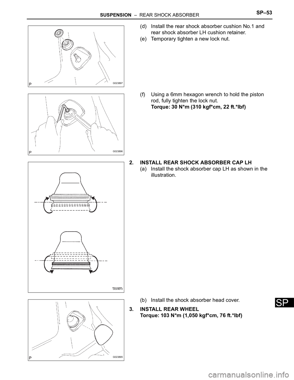
(d) Install the rear shock absorber cushion No.1 and
rear shock absorber LH cushion retainer.
(e) Temporary tighten a new lock nut.
(f) Using a 6mm hexagon wrench to hold the piston
rod, fully tighten the lock nut.
Torque: 30 N*m (310 kgf*cm, 22 ft.*lbf)
2. INSTALL REAR SHOCK ABSORBER CAP LH
(a) Install the shock absorber cap LH as shown in the
illustration.
(b) Install the shock absorber head cover.
3. INSTALL REAR WHEEL
Torque: 103 N*m (1,050 kgf*cm, 76 ft.*lbf)
G023897
G023896
G024672
G023895
Page 172 of 3000
SP–54SUSPENSION – REAR SHOCK ABSORBER
SP
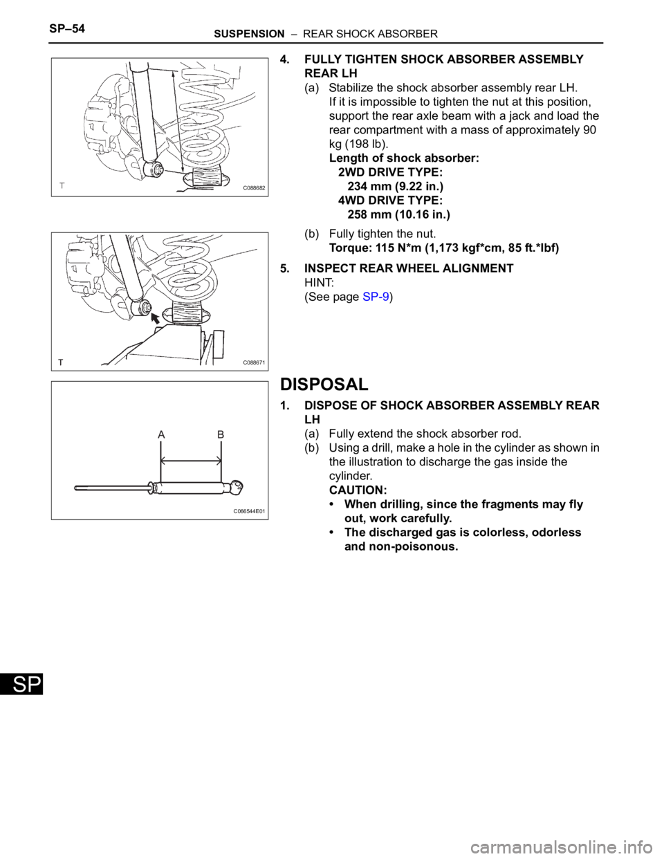
4. FULLY TIGHTEN SHOCK ABSORBER ASSEMBLY
REAR LH
(a) Stabilize the shock absorber assembly rear LH.
If it is impossible to tighten the nut at this position,
support the rear axle beam with a jack and load the
rear compartment with a mass of approximately 90
kg (198 lb).
Length of shock absorber:
2WD DRIVE TYPE:
234 mm (9.22 in.)
4WD DRIVE TYPE:
258 mm (10.16 in.)
(b) Fully tighten the nut.
Torque: 115 N*m (1,173 kgf*cm, 85 ft.*lbf)
5. INSPECT REAR WHEEL ALIGNMENT
HINT:
(See page SP-9)
DISPOSAL
1. DISPOSE OF SHOCK ABSORBER ASSEMBLY REAR
LH
(a) Fully extend the shock absorber rod.
(b) Using a drill, make a hole in the cylinder as shown in
the illustration to discharge the gas inside the
cylinder.
CAUTION:
• When drilling, since the fragments may fly
out, work carefully.
• The discharged gas is colorless, odorless
and non-poisonous.
C088682
C088671
C066544E01
Page 217 of 3000
SS–46SERVICE SPECIFICATIONS – DIFFERENTIAL
SS
TORQUE SPECIFICATIONS
Part tightened N*m kgf*cm ft*lbf
Drain plug 49 500 36
Filler plug 49 500 36
Breather plug 21 210 15
Companion flange x Drive pinion 108 1,100 80
Companion flange x Propeller shaft 74 750 55
Differential case x Ring gear 97 985 71
Differential carrier x Side bearing cap 79 800 58
Differential carrier x Differential carrier cover 47 475 34
Rear differential support No.1 x Differential carrier assembly 8586763
Rear differential support No.1 x Rear suspension member sub-assembly 95 969 70
Differential carrier assembly x Rear suspension member sub-assembly 106 1,081 78
Page 870 of 3000
2GR-FE ENGINE MECHANICAL – ENGINE ASSEMBLYEM–53
EM
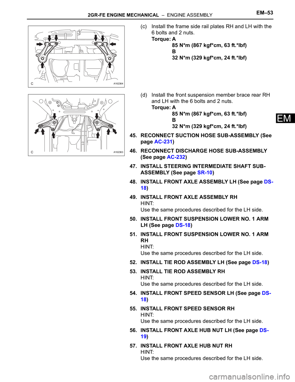
(c) Install the frame side rail plates RH and LH with the
6 bolts and 2 nuts.
Torque: A
85 N*m (867 kgf*cm, 63 ft.*lbf)
B
32 N*m (329 kgf*cm, 24 ft.*lbf)
(d) Install the front suspension member brace rear RH
and LH with the 6 bolts and 2 nuts.
Torque: A
85 N*m (867 kgf*cm, 63 ft.*lbf)
B
32 N*m (329 kgf*cm, 24 ft.*lbf)
45. RECONNECT SUCTION HOSE SUB-ASSEMBLY (See
page AC-231)
46. RECONNECT DISCHARGE HOSE SUB-ASSEMBLY
(See page AC-232)
47. INSTALL STEERING INTERMEDIATE SHAFT SUB-
ASSEMBLY (See page SR-10)
48. INSTALL FRONT AXLE ASSEMBLY LH (See page DS-
18)
49. INSTALL FRONT AXLE ASSEMBLY RH
HINT:
Use the same procedures described for the LH side.
50. INSTALL FRONT SUSPENSION LOWER NO. 1 ARM
LH (See page DS-18)
51. INSTALL FRONT SUSPENSION LOWER NO. 1 ARM
RH
HINT:
Use the same procedures described for the LH side.
52. INSTALL TIE ROD ASSEMBLY LH (See page DS-18)
53. INSTALL TIE ROD ASSEMBLY RH
HINT:
Use the same procedures described for the LH side.
54. INSTALL FRONT SPEED SENSOR LH (See page DS-
18)
55. INSTALL FRONT SPEED SENSOR RH
HINT:
Use the same procedures described for the LH side.
56. INSTALL FRONT AXLE HUB NUT LH (See page DS-
19)
57. INSTALL FRONT AXLE HUB NUT RH
HINT:
Use the same procedures described for the LH side.
A162364
A162363
Page 993 of 3000
EM–342GR-FE ENGINE MECHANICAL – ENGINE ASSEMBLY
EM
45. REMOVE PROPELLER WITH CENTER BEARING
SHAFT ASSEMBLY (See page PR-3)
46. DISCONNECT FRONT STABILIZER LINK ASSEMBLY
LH (See page DS-5)
47. DISCONNECT FRONT STABILIZER LINK ASSEMBLY
RH
HINT:
Use the same procedures described for the LH side.
48. REMOVE FRONT AXLE HUB NUT LH (See page DS-
5)
49. REMOVE FRONT AXLE HUB NUT RH
HINT:
Use the same procedures described for the LH side.
50. DISCONNECT FRONT SPEED SENSOR LH (See page
DS-5)
51. DISCONNECT FRONT SPEED SENSOR RH
HINT:
Use the same procedures described for the LH side.
52. DISCONNECT TIE ROD ASSEMBLY LH (See page
DS-6)
53. DISCONNECT TIE ROD ASSEMBLY RH
HINT:
Use the same procedures described for the LH side.
54. SEPARATE FRONT SUSPENSION LOWER NO. 1
ARM LH (See page DS-6)
55. SEPARATE FRONT SUSPENSION LOWER NO. 1
ARM RH
HINT:
Use the same procedures described for the LH side.
56. SEPARATE FRONT AXLE ASSEMBLY LH (See page
DS-6)
57. SEPARATE FRONT AXLE ASSEMBLY RH
HINT:
Use the same procedures described for the LH side.
58. DISCONNECT STEERING INTERMEDIATE SHAFT
SUB-ASSEMBLY
59. DISCONNECT DISCHARGE HOSE SUB-ASSEMBLY
(See page AC-227)
60. DISCONNECT SUCTION HOSE SUB-ASSEMBLY (See
page AC-227)
61. REMOVE ENGINE ASSEMBLY WITH TRANSAXLE
(a) Set the engine lifter.
Page 994 of 3000
2GR-FE ENGINE MECHANICAL – ENGINE ASSEMBLYEM–35
EM
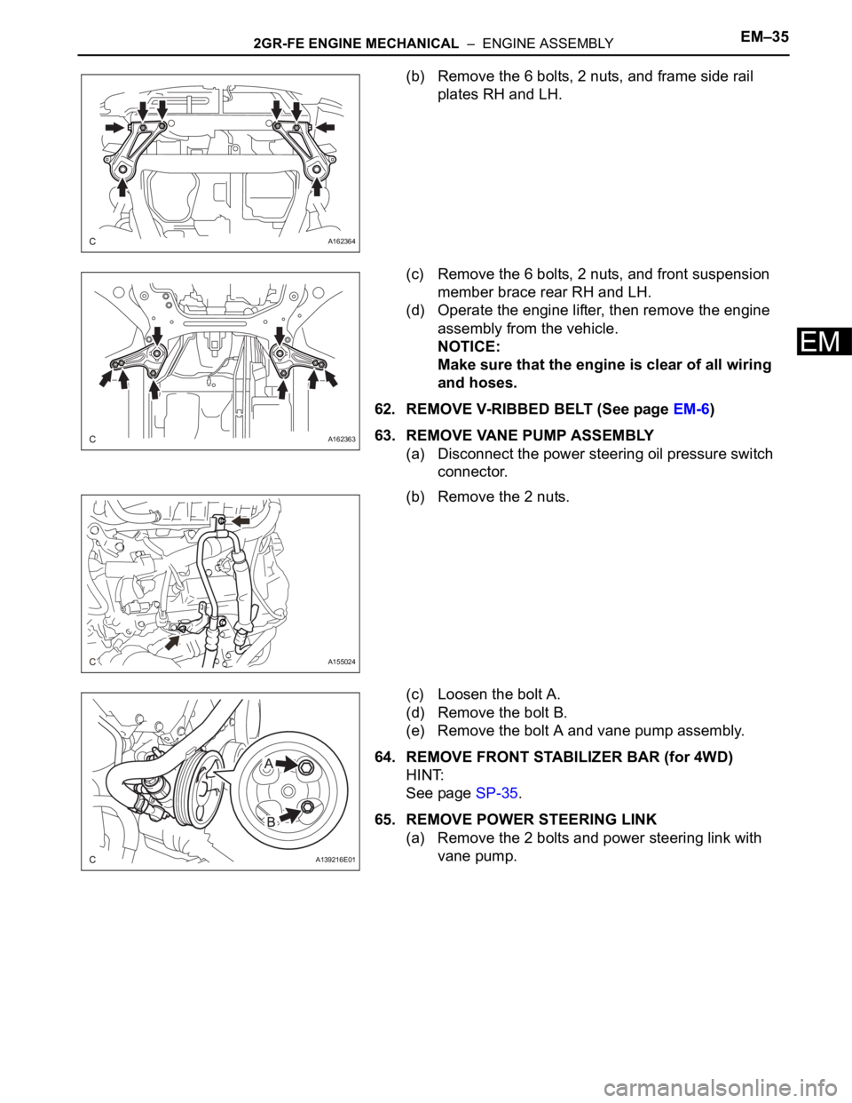
(b) Remove the 6 bolts, 2 nuts, and frame side rail
plates RH and LH.
(c) Remove the 6 bolts, 2 nuts, and front suspension
member brace rear RH and LH.
(d) Operate the engine lifter, then remove the engine
assembly from the vehicle.
NOTICE:
Make sure that the engine is clear of all wiring
and hoses.
62. REMOVE V-RIBBED BELT (See page EM-6)
63. REMOVE VANE PUMP ASSEMBLY
(a) Disconnect the power steering oil pressure switch
connector.
(b) Remove the 2 nuts.
(c) Loosen the bolt A.
(d) Remove the bolt B.
(e) Remove the bolt A and vane pump assembly.
64. REMOVE FRONT STABILIZER BAR (for 4WD)
HINT:
See page SP-35.
65. REMOVE POWER STEERING LINK
(a) Remove the 2 bolts and power steering link with
vane pump.
A162364
A162363
A155024
A139216E01
Page 1012 of 3000
2GR-FE ENGINE MECHANICAL – ENGINE ASSEMBLYEM–53
EM
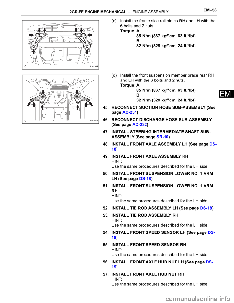
(c) Install the frame side rail plates RH and LH with the
6 bolts and 2 nuts.
Torque: A
85 N*m (867 kgf*cm, 63 ft.*lbf)
B
32 N*m (329 kgf*cm, 24 ft.*lbf)
(d) Install the front suspension member brace rear RH
and LH with the 6 bolts and 2 nuts.
Torque: A
85 N*m (867 kgf*cm, 63 ft.*lbf)
B
32 N*m (329 kgf*cm, 24 ft.*lbf)
45. RECONNECT SUCTION HOSE SUB-ASSEMBLY (See
page AC-231)
46. RECONNECT DISCHARGE HOSE SUB-ASSEMBLY
(See page AC-232)
47. INSTALL STEERING INTERMEDIATE SHAFT SUB-
ASSEMBLY (See page SR-10)
48. INSTALL FRONT AXLE ASSEMBLY LH (See page DS-
18)
49. INSTALL FRONT AXLE ASSEMBLY RH
HINT:
Use the same procedures described for the LH side.
50. INSTALL FRONT SUSPENSION LOWER NO. 1 ARM
LH (See page DS-18)
51. INSTALL FRONT SUSPENSION LOWER NO. 1 ARM
RH
HINT:
Use the same procedures described for the LH side.
52. INSTALL TIE ROD ASSEMBLY LH (See page DS-18)
53. INSTALL TIE ROD ASSEMBLY RH
HINT:
Use the same procedures described for the LH side.
54. INSTALL FRONT SPEED SENSOR LH (See page DS-
18)
55. INSTALL FRONT SPEED SENSOR RH
HINT:
Use the same procedures described for the LH side.
56. INSTALL FRONT AXLE HUB NUT LH (See page DS-
19)
57. INSTALL FRONT AXLE HUB NUT RH
HINT:
Use the same procedures described for the LH side.
A162364
A162363
Page 2073 of 3000
DRIVE SHAFT – FRONT DRIVE SHAFTDS–19
DS
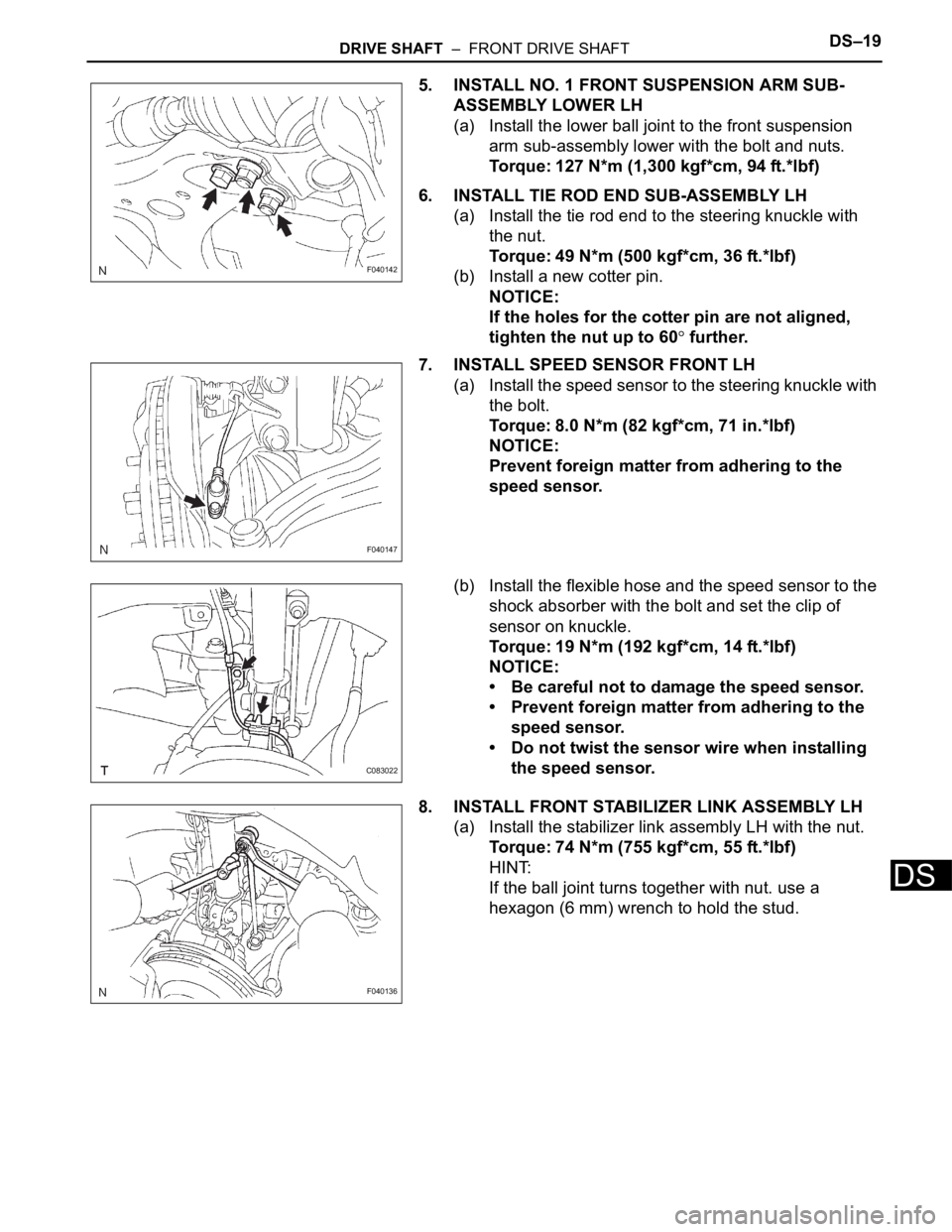
5. INSTALL NO. 1 FRONT SUSPENSION ARM SUB-
ASSEMBLY LOWER LH
(a) Install the lower ball joint to the front suspension
arm sub-assembly lower with the bolt and nuts.
Torque: 127 N*m (1,300 kgf*cm, 94 ft.*lbf)
6. INSTALL TIE ROD END SUB-ASSEMBLY LH
(a) Install the tie rod end to the steering knuckle with
the nut.
Torque: 49 N*m (500 kgf*cm, 36 ft.*lbf)
(b) Install a new cotter pin.
NOTICE:
If the holes for the cotter pin are not aligned,
tighten the nut up to 60
further.
7. INSTALL SPEED SENSOR FRONT LH
(a) Install the speed sensor to the steering knuckle with
the bolt.
Torque: 8.0 N*m (82 kgf*cm, 71 in.*lbf)
NOTICE:
Prevent foreign matter from adhering to the
speed sensor.
(b) Install the flexible hose and the speed sensor to the
shock absorber with the bolt and set the clip of
sensor on knuckle.
Torque: 19 N*m (192 kgf*cm, 14 ft.*lbf)
NOTICE:
• Be careful not to damage the speed sensor.
• Prevent foreign matter from adhering to the
speed sensor.
• Do not twist the sensor wire when installing
the speed sensor.
8. INSTALL FRONT STABILIZER LINK ASSEMBLY LH
(a) Install the stabilizer link assembly LH with the nut.
Torque: 74 N*m (755 kgf*cm, 55 ft.*lbf)
HINT:
If the ball joint turns together with nut. use a
hexagon (6 mm) wrench to hold the stud.
F040142
F040147
C083022
F040136