Page 615 of 3000

ES–3222GR-FE ENGINE CONTROL SYSTEM – SFI SYSTEM
ES
DESCRIPTION
The ECM continuously monitors its internal processors (CPUs), A/F sensor transistors and heated oxygen
sensor (HO2S) transistors. This self-check ensures that the ECM is functioning properly. These are
diagnosed by internal "mirroring" of the main and sub CPUs to detect the processors error. If outputs from
the processors deviate from the standards, the ECM will illuminate the MIL and set a DTC immediately.
MONITOR STRATEGY
TYPICAL ENABLING CONDITIONS
TYPICAL MALFUNCTION THRESHOLDS
INSPECTION PROCEDURE
(a) Allow the engine to idle.
(b) Check for exhaust gas leak around the heated oxygen
sensor.
OK:
No leak from the heated oxygen sensor.
NG
DTC P0606 ECM / PCM Processor
DTC DTC Setting Condition Trouble Area
P0606• ECM CPUs malfunction
• A/F sensor transistors malfunction
• HO2S transistors malfunction• Exhaust gas leak
•HO2 Sensor
•ECM
Related DTC P0606: ECM range check
Required sensors/Components (main) ECM
Required sensors/Components (sub)APP sensor, TP sensor, Brake switch, Cruise control, A/F sensor,
HO2 sensor
Frequency of Operation Continuous
Duration 60 seconds
MIL Operation Immediate
Sequence of Operation None
Monitor runs whenever the following DTCs are not present None
Engine Running
Estimated A/F sensor temperature 450 to 800
C (842 to 1472F)
Estimated HO2S temperature 450 to 800
C (842 to 1472F)
Difference of main APP and sub APP 0.3 V or more
Difference of main TP and sub TP 0.3 V or more
Difference of main brake switch signal and sub brake switch signal Different
Cruise control Fail
A/F sensor transistors Fail
HO2S transistors Fail
1INSPECT FOR EXHAUST GAS LEAK
REPAIR OR REPLACE EXHAUST GAS
LEAKAGE POINT
Page 855 of 3000

MP–12MULTIPLEX COMMUNICATION – MULTIPLEX COMMUNICATION SYSTEM
MP
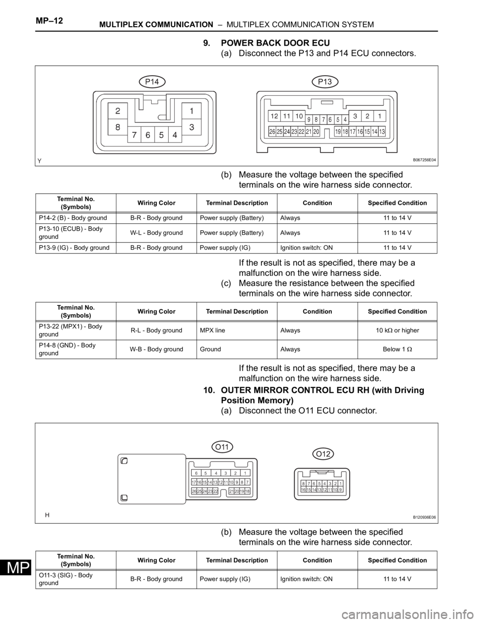
9. POWER BACK DOOR ECU
(a) Disconnect the P13 and P14 ECU connectors.
(b) Measure the voltage between the specified
terminals on the wire harness side connector.
If the result is not as specified, there may be a
malfunction on the wire harness side.
(c) Measure the resistance between the specified
terminals on the wire harness side connector.
If the result is not as specified, there may be a
malfunction on the wire harness side.
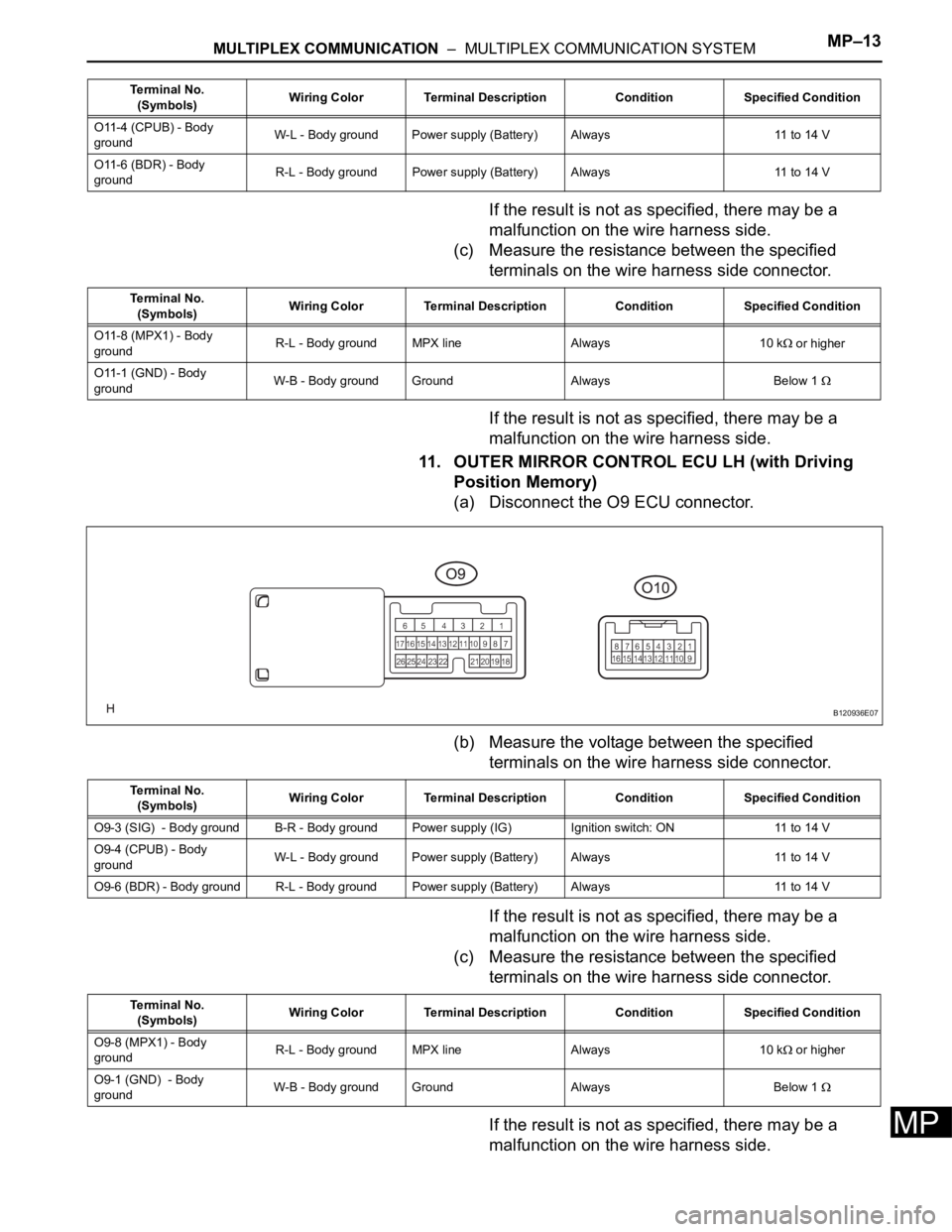
10. OUTER MIRROR CONTROL ECU RH (with Driving
Position Memory)
(a) Disconnect the O11 ECU connector.
(b) Measure the voltage between the specified
terminals on the wire harness side connector.
B067256E04
Te r m i n a l N o .
(Symbols)Wiring Color Terminal Description Condition Specified Condition
P14-2 (B) - Body ground B-R - Body ground Power supply (Battery) Always 11 to 14 V
P13-10 (ECUB) - Body
groundW-L - Body ground Power supply (Battery) Always 11 to 14 V
P13-9 (IG) - Body ground B-R - Body ground Power supply (IG) Ignition switch: ON 11 to 14 V
Te r m i n a l N o .
(Symbols)Wiring Color Terminal Description Condition Specified Condition
P13-22 (MPX1) - Body
groundR-L - Body ground MPX line Always 10 k
or higher
P14-8 (GND) - Body
groundW-B - Body ground Ground Always Below 1
B120936E06
Te r m i n a l N o .
(Symbols)Wiring Color Terminal Description Condition Specified Condition
O11-3 (SIG) - Body
groundB-R - Body ground Power supply (IG) Ignition switch: ON 11 to 14 V
Page 856 of 3000

MULTIPLEX COMMUNICATION – MULTIPLEX COMMUNICATION SYSTEMMP–13
MP
If the result is not as specified, there may be a
malfunction on the wire harness side.
(c) Measure the resistance between the specified
terminals on the wire harness side connector.
If the result is not as specified, there may be a
malfunction on the wire harness side.
11. OUTER MIRROR CONTROL ECU LH (with Driving
Position Memory)
(a) Disconnect the O9 ECU connector.
(b) Measure the voltage between the specified
terminals on the wire harness side connector.
If the result is not as specified, there may be a
malfunction on the wire harness side.
(c) Measure the resistance between the specified
terminals on the wire harness side connector.
If the result is not as specified, there may be a
malfunction on the wire harness side.
O11-4 (CPUB) - Body
groundW-L - Body ground Power supply (Battery) Always 11 to 14 V
O11-6 (BDR) - Body
groundR-L - Body ground Power supply (Battery) Always 11 to 14 V Terminal No.
(Symbols)Wiring Color Terminal Description Condition Specified Condition
Terminal No.
(Symbols)Wiring Color Terminal Description Condition Specified Condition
O11-8 (MPX1) - Body
groundR-L - Body ground MPX line Always 10 k
or higher
O11-1 (GND) - Body
groundW-B - Body ground Ground Always Below 1
B120936E07
Terminal No.
(Symbols)Wiring Color Terminal Description Condition Specified Condition
O9-3 (SIG) - Body ground B-R - Body ground Power supply (IG) Ignition switch: ON 11 to 14 V
O9-4 (CPUB) - Body
groundW-L - Body ground Power supply (Battery) Always 11 to 14 V
O9-6 (BDR) - Body ground R-L - Body ground Power supply (Battery)Always 11 to 14 V
Terminal No.
(Symbols)Wiring Color Terminal Description Condition Specified Condition
O9-8 (MPX1) - Body
groundR-L - Body ground MPX line Always 10 k
or higher
O9-1 (GND) - Body
groundW-B - Body ground Ground Always Below 1