2007 TOYOTA SIENNA brake sensor
[x] Cancel search: brake sensorPage 181 of 3000
BRAKE CONTROL – ANTI-LOCK BRAKE SYSTEMBC–5
BC
• After the ABS warning light goes off and if
vehicle speed exceeds 50 mph (80 km/h), the
signal check code will be stored again.
Decelerate or stop the vehicle before the
speed reaches 50 mph (80 km/h).
• If the signal check has not been completed,
the ABS warning light blinks while driving
and the ABS system does not operate.
HINT:
When the signal check has been completed, the
ABS warning light goes off while driving and blinks
in the Test Mode pattern while stationary.
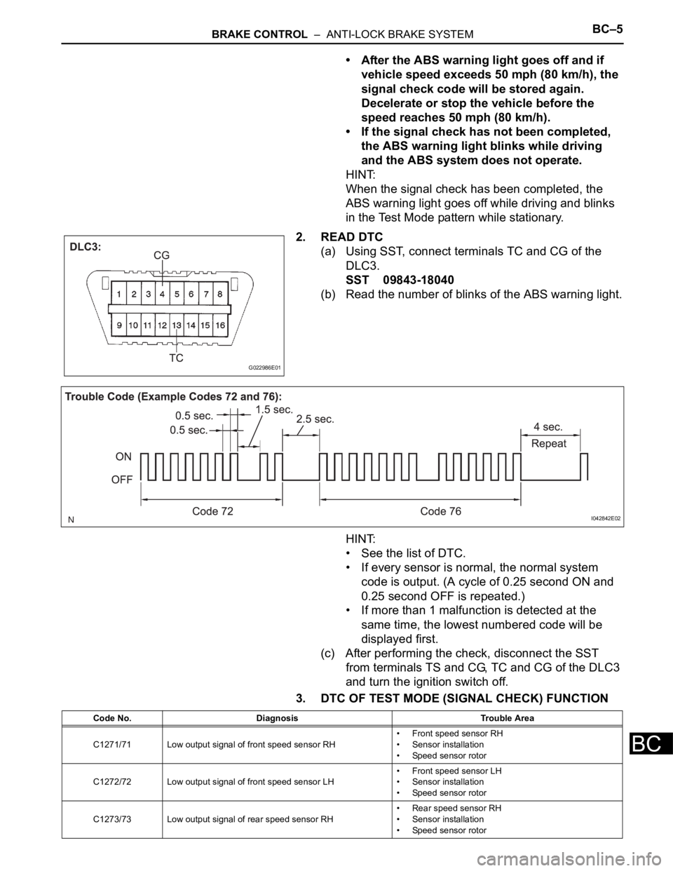
2. READ DTC
(a) Using SST, connect terminals TC and CG of the
DLC3.
SST 09843-18040
(b) Read the number of blinks of the ABS warning light.
HINT:
• See the list of DTC.
• If every sensor is normal, the normal system
code is output. (A cycle of 0.25 second ON and
0.25 second OFF is repeated.)
• If more than 1 malfunction is detected at the
same time, the lowest numbered code will be
displayed first.
(c) After performing the check, disconnect the SST
from terminals TS and CG, TC and CG of the DLC3
and turn the ignition switch off.
3. DTC OF TEST MODE (SIGNAL CHECK) FUNCTION
G022986E01
I042842E02
Code No. Diagnosis Trouble Area
C1271/71 Low output signal of front speed sensor RH• Front speed sensor RH
• Sensor installation
• Speed sensor rotor
C1272/72 Low output signal of front speed sensor LH• Front speed sensor LH
• Sensor installation
• Speed sensor rotor
C1273/73 Low output signal of rear speed sensor RH• Rear speed sensor RH
• Sensor installation
• Speed sensor rotor
Page 182 of 3000
BC–6BRAKE CONTROL – ANTI-LOCK BRAKE SYSTEM
BC
HINT:
The codes in this table are output only in Test Mode
(signal check).
4. SPEED SENSOR SIGNAL CHECK (WHEN USING
INTELLIGENT TESTER):
HINT:
• If the ignition switch is turned from the ON to the ACC
or LOCK position during Test Mode, DTCs of the
signal check function will be erased.
• During Test Mode, the ECU records all DTCs of the
signal check function. By performing the signal check,
the codes are erased if normality is confirmed. The
remaining codes are the codes where an abnormality
was found.
(a) Turn the ignition switch off.
(b) Check that the steering wheel is in the straight-
ahead position.
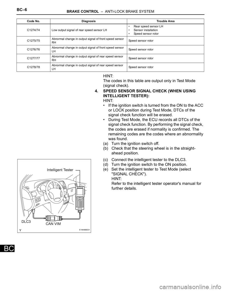
(c) Connect the intelligent tester to the DLC3.
(d) Turn the ignition switch to the ON position.
(e) Set the intelligent tester to Test Mode (select
"SIGNAL CHECK").
HINT:
Refer to the intelligent tester operator's manual for
further details.
C1274/74 Low output signal of rear speed sensor LH• Rear speed sensor LH
• Sensor installation
• Speed sensor rotor
C1275/75Abnormal change in output signal of front speed sensor
RHSpeed sensor rotor
C1276/76Abnormal change in output signal of front speed sensor
LHSpeed sensor rotor
C1277/77Abnormal change in output signal of rear speed sensor
RHSpeed sensor rotor
C1278/78Abnormal change in output signal of rear speed sensor
LHSpeed sensor rotor Code No. Diagnosis Trouble Area
E144486E01
Page 183 of 3000
BRAKE CONTROL – ANTI-LOCK BRAKE SYSTEMBC–7
BC
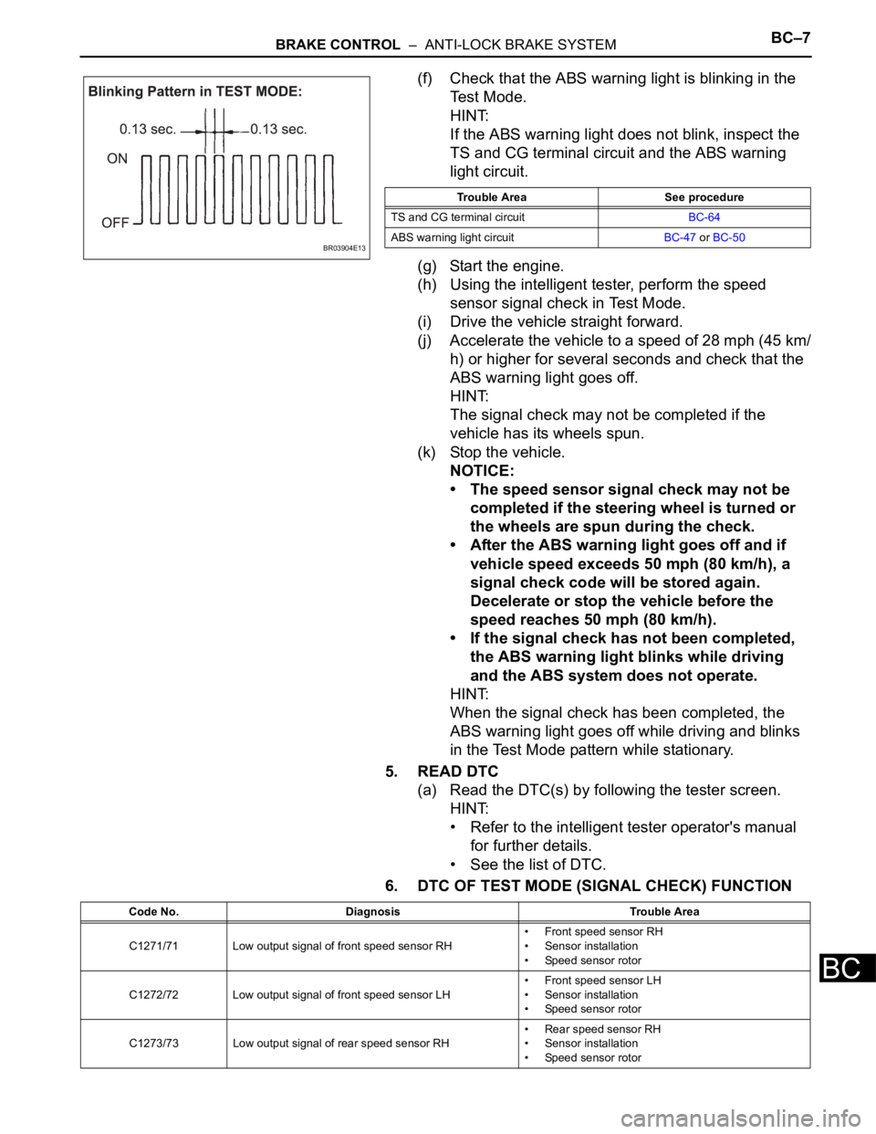
(f) Check that the ABS warning light is blinking in the
Test Mode.
HINT:
If the ABS warning light does not blink, inspect the
TS and CG terminal circuit and the ABS warning
light circuit.
(g) Start the engine.
(h) Using the intelligent tester, perform the speed
sensor signal check in Test Mode.
(i) Drive the vehicle straight forward.
(j) Accelerate the vehicle to a speed of 28 mph (45 km/
h) or higher for several seconds and check that the
ABS warning light goes off.
HINT:
The signal check may not be completed if the
vehicle has its wheels spun.
(k) Stop the vehicle.
NOTICE:
• The speed sensor signal check may not be
completed if the steering wheel is turned or
the wheels are spun during the check.
• After the ABS warning light goes off and if
vehicle speed exceeds 50 mph (80 km/h), a
signal check code will be stored again.
Decelerate or stop the vehicle before the
speed reaches 50 mph (80 km/h).
• If the signal check has not been completed,
the ABS warning light blinks while driving
and the ABS system does not operate.
HINT:
When the signal check has been completed, the
ABS warning light goes off while driving and blinks
in the Test Mode pattern while stationary.
5. READ DTC
(a) Read the DTC(s) by following the tester screen.
HINT:
• Refer to the intelligent tester operator's manual
for further details.
• See the list of DTC.
6. DTC OF TEST MODE (SIGNAL CHECK) FUNCTION
BR03904E13
Trouble Area See procedure
TS and CG terminal circuitBC-64
ABS warning light circuitBC-47 or BC-50
Code No. Diagnosis Trouble Area
C1271/71 Low output signal of front speed sensor RH• Front speed sensor RH
• Sensor installation
• Speed sensor rotor
C1272/72 Low output signal of front speed sensor LH• Front speed sensor LH
• Sensor installation
• Speed sensor rotor
C1273/73 Low output signal of rear speed sensor RH• Rear speed sensor RH
• Sensor installation
• Speed sensor rotor
Page 184 of 3000

BC–8BRAKE CONTROL – ANTI-LOCK BRAKE SYSTEM
BC
HINT:
The codes in this table are output only in Test Mode
(signal check).
C1274/74 Low output signal of rear speed sensor LH• Rear speed sensor LH
• Sensor installation
• Speed sensor rotor
C1275/75Abnormal change in output signal of front speed sensor
RHSpeed sensor rotor
C1276/76Abnormal change in output signal of front speed sensor
LHSpeed sensor rotor
C1277/77Abnormal change in output signal of rear speed sensor
RHSpeed sensor rotor
C1278/78Abnormal change in output signal of rear speed sensor
LHSpeed sensor rotor Code No. Diagnosis Trouble Area
Page 214 of 3000

SERVICE SPECIFICATIONS – U151F AUTOMATIC TRANSAXLESS–37
SS
TORQUE SPECIFICATIONS
Part Tightened N*m kgf*cm ft*lbf
Park/neutral position switch Nut 6.9 70 61 in.*lbf
Bolt 5.4 55 48 in.*lbf
Control shaft lever x Control shaft 13 130 9
Shift control cable x Control shaft lever 13 130 9
Transaxle housing x Engine block A bolt 64 653 47
B bolt 46 470 34
C bolt 43 439 32
Torque converter clutch x Drive plate 41 413 30
Flywheel housing under cover x Automatic transaxle 7.8 80 69 in.*lbf
Engine mounting bracket FR x Transaxle 64 653 47
Oil filler tube x Transaxle5.5 56 49 in.*lbf
Control cable bracket No. 1 x Transaxle 12 122 9
Control cable bracket No. 2 x Transaxle 12 122 9
Oil cooler tube clamp x Control cable bracket 5.5 56 49 in.*lbf
Oil cooler inlet tube x Transaxle27 275 20
Oil cooler outlet tube x Transaxle 27 275 20
Starter x Transaxle37 377 27
Starter wire x Starter9.8 100 87 in.*lbf
Wire harness x Transaxle13 133 10
Wire harness clamp x Transaxle8.4 86 74 in.*lbf
Speed sensor (NC) x Transaxle11 11 5 8
Speed sensor (NT) x Transaxle11 11 2 8
Air cleaner x Air cleaner hose5.0 51 44 in.*lbf
Drain plug x Oil pan49 500 36
Transmission wire x Transaxle5.4 55 48 in.*lbf
ATF temperature sensor x Valve body 6.6 67 58 in.*lbf
Oil pan x Transaxle7.8 80 69 in.*lbf
Solenoid valve x Valve body A B bolt 11 110 8
C D bolt 6.6 67 58 in.*lbf
Valve body x Transaxle11 11 0 8
Oil strainer x Valve body11 11 0 8
Floor shift assembly x Body21 214 15
Control cable x Body12 122 9
Transfer x Transaxle69 700 51
Transfer x Transfer stiffener plate RH 34 350 25
Engine mount bracket RR x Transfer stiffener plate RH 34 350 25
Oil cooler assembly x Body Nut
7.0 71 62 in.*lbf
bolt
Differential gear lube apply tube x Transaxle housing 9.8 100 87 in.*lbf
Front planetary gear lock nut
210 to 3502,141 to
3,569155 to 258
Brake apply tube clamp x Transaxle case 5.4 55 48 in.*lbf
Transaxle case No. 1 plug x Transaxle rear cover 7.4 75 65 in.*lbf
Transaxle rear cover x Transaxle case Bolt A 19 190 14
Other bolt 25 250 18
Pawl shaft clamp x Transaxle case 9.8 100 87 in.*lbf
Oil pump assembly x Transaxle case 22 226 16
Page 354 of 3000

ES–282GR-FE ENGINE CONTROL SYSTEM – SFI SYSTEM
ES
• Vehicle was driven in the city area (or on free-
way) for 10 minutes or more.
(b) Monitor Conditions
(1) Turn the ignition switch off and wait for 6 hours.
HINT:
Do not start the engine until checking Readiness
Monitor status. If the engine is started, the step
described above must be repeated.
(c) Monitor Status
(1) Connect an intelligent tester to the DLC3.
(2) Turn the ignition switch to the ON position.
(3) Turn the tester or scan tool ON.
(4) Check the Readiness Monitor status displayed
on the tester or scan tool.
If the status does not switch to COMPL
(complete), restart the engine, make sure that
the preconditions have been met, and then
perform the Monitor Conditions again.
4. A/F SENSOR AND HO2S MONITORS
(a) Preconditions
The monitor will not run unless:
• 2 minutes or more have elapsed since the engine
was started.
• The Engine Coolant Temperature (ECT) is 75
C
(167
F) or more.
• Cumulative driving time at a vehicle speed of 30
mph (48 km/h) or more exceeds 6 minutes.
• Air-fuel ratio feedback control is performed.
• Fuel-cut control is performed for 8 seconds or
more (for the Rear HO2 Sensor Monitor).
(b) Drive Pattern for front A/F sensor and HO2 sensor.
(1) Connect an intelligent tester to the DLC3.
(2) Turn the ignition switch to the ON position.
(3) Turn the tester ON.
(4) Clear the DTCs.
(5) Start the engine, and warm it up until the ECT
reaches 75
C (167F) or higher.
(6) Drive the vehicle at 38 mph (60 km/h) or more
for at least 10 minutes.
(7) Change the transmission to the 2nd gear.
(8) Accelerate the vehicle to 40 mph (64 km/h) or
more by depressing the accelerator pedal for at
least 10 seconds (Procedure "A").
(9) Soon after performing procedure "A" above,
release the accelerator pedal for at least 4
seconds without depressing the brake pedal, in
order to execute fuel-cut control (Procedure "B").
(10) Allow the vehicle to decelerate until the vehicle
speed declines to less than 6 mph (10 km/h)
(Procedure "C").
(11) Repeat procedures from "A" through "C" above
at least 3 times in one driving cycle.
Page 382 of 3000
ES–762GR-FE ENGINE CONTROL SYSTEM – SFI SYSTEM
ES
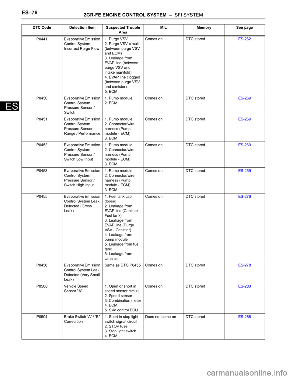
P0441 Evaporative Emission
Control System
Incorrect Purge Flow1. Purge VSV
2. Purge VSV circuit
(between purge VSV
and ECM)
3. Leakage from
EVAP line (between
purge VSV and
intake manifold)
4. EVAP line clogged
(between purge VSV
and canister)
5. ECMComes on DTC storedES-262
P0450 Evaporative Emission
Control System
Pressure Sensor /
Switch1. Pump module
2. ECMComes on DTC storedES-269
P0451 Evaporative Emission
Control System
Pressure Sensor
Range / Performance1. Pump module
2. Connector/wire
harness (Pump
module - ECM)
3. ECMComes on DTC storedES-269
P0452 Evaporative Emission
Control System
Pressure Sensor /
Switch Low Input1. Pump module
2. Connector/wire
harness (Pump
module - ECM)
3. ECMComes on DTC storedES-269
P0453 Evaporative Emission
Control System
Pressure Sensor /
Switch High Input1. Pump module
2. Connector/wire
harness (Pump
module - ECM)
3. ECMComes on DTC storedES-269
P0455 Evaporative Emission
Control System Leak
Detected (Gross
Leak)1. Fuel tank cap
(loose)
2. Leakage from
EVAP line (Canister -
Fuel tank)
3. Leakage from
EVAP line (Purge
VSV - Canister)
4. Leakage from
pump module
5. Leakage from fuel
tank
6. Leakage from
canisterComes on DTC storedES-278
P0456 Evaporative Emission
Control System Leak
Detected (Very Small
Leak)Same as DTC P0455 Comes on DTC storedES-278
P0500 Vehicle Speed
Sensor "A"1. Open or short in
speed sensor circuit
2. Speed sensor
3. Combination meter
4. ECM
5. Skid control ECUComes on DTC storedES-283
P0504 Brake Switch "A" / "B"
Correlation1. Short in stop light
switch signal circuit
2. STOP fuse
3. Stop light switch
4. ECMDoes not come on DTC storedES-288 DTC Code Detection Item Suspected Trouble
AreaMIL Memory See page
Page 384 of 3000
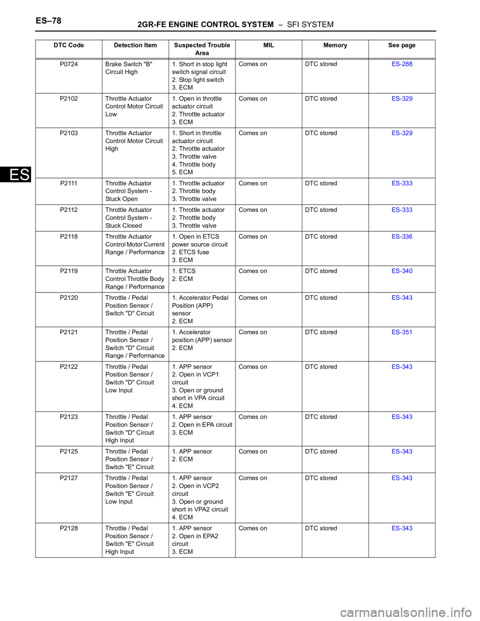
ES–782GR-FE ENGINE CONTROL SYSTEM – SFI SYSTEM
ES
P0724 Brake Switch "B"
Circuit High1. Short in stop light
switch signal circuit
2. Stop light switch
3. ECMComes on DTC storedES-288
P2102 Throttle Actuator
Control Motor Circuit
Low1. Open in throttle
actuator circuit
2. Throttle actuator
3. ECMComes on DTC storedES-329
P2103 Throttle Actuator
Control Motor Circuit
High1. Short in throttle
actuator circuit
2. Throttle actuator
3. Throttle valve
4. Throttle body
5. ECMComes on DTC storedES-329
P2111 Throttle Actuator
Control System -
Stuck Open1. Throttle actuator
2. Throttle body
3. Throttle valveComes on DTC storedES-333
P2112 Throttle Actuator
Control System -
Stuck Closed1. Throttle actuator
2. Throttle body
3. Throttle valveComes on DTC storedES-333
P2118 Throttle Actuator
Control Motor Current
Range / Performance1. Open in ETCS
power source circuit
2. ETCS fuse
3. ECMComes on DTC storedES-336
P2119 Throttle Actuator
Control Throttle Body
Range / Performance1. ETCS
2. ECMComes on DTC storedES-340
P2120 Throttle / Pedal
Position Sensor /
Switch "D" Circuit1. Accelerator Pedal
Position (APP)
sensor
2. ECMComes on DTC storedES-343
P2121 Throttle / Pedal
Position Sensor /
Switch "D" Circuit
Range / Performance1. Accelerator
position (APP) sensor
2. ECMComes on DTC storedES-351
P2122 Throttle / Pedal
Position Sensor /
Switch "D" Circuit
Low Input1. APP sensor
2. Open in VCP1
circuit
3. Open or ground
short in VPA circuit
4. ECMComes on DTC storedES-343
P2123 Throttle / Pedal
Position Sensor /
Switch "D" Circuit
High Input1. APP sensor
2. Open in EPA circuit
3. ECMComes on DTC storedES-343
P2125 Throttle / Pedal
Position Sensor /
Switch "E" Circuit1. APP sensor
2. ECMComes on DTC storedES-343
P2127 Throttle / Pedal
Position Sensor /
Switch "E" Circuit
Low Input1. APP sensor
2. Open in VCP2
circuit
3. Open or ground
short in VPA2 circuit
4. ECMComes on DTC storedES-343
P2128 Throttle / Pedal
Position Sensor /
Switch "E" Circuit
High Input1. APP sensor
2. Open in EPA2
circuit
3. ECMComes on DTC storedES-343 DTC Code Detection Item Suspected Trouble
AreaMIL Memory See page