Page 215 of 3000
SS–38SERVICE SPECIFICATIONS – U151F AUTOMATIC TRANSAXLE
SS
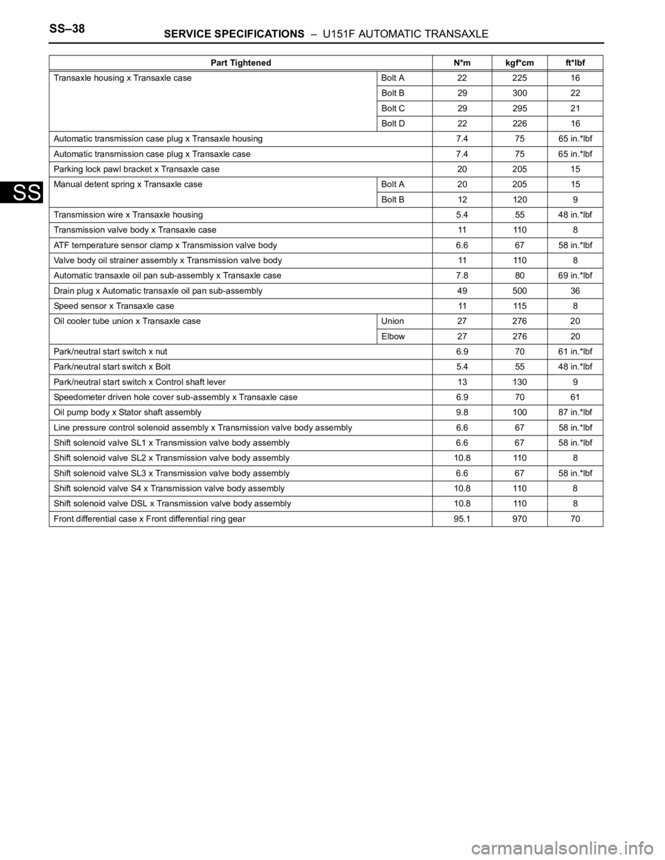
Transaxle housing x Transaxle case Bolt A 22 225 16
Bolt B 29 300 22
Bolt C 29 295 21
Bolt D 22 226 16
Automatic transmission case plug x Transaxle housing 7.4 75 65 in.*lbf
Automatic transmission case plug x Transaxle case 7.4 75 65 in.*lbf
Parking lock pawl bracket x Transaxle case 20 205 15
Manual detent spring x Transaxle case Bolt A 20 205 15
Bolt B 12 120 9
Transmission wire x Transaxle housing 5.4 55 48 in.*lbf
Transmission valve body x Transaxle case 11 110 8
ATF temperature sensor clamp x Transmission valve body 6.6 67 58 in.*lbf
Valve body oil strainer assembly x Transmission valve body 11 1108
Automatic transaxle oil pan sub-assembly x Transaxle case 7.8 80 69 in.*lbf
Drain plug x Automatic transaxle oil pan sub-assembly 49 500 36
Speed sensor x Transaxle case11 11 5 8
Oil cooler tube union x Transaxle case Union 27 276 20
Elbow 27 276 20
Park/neutral start switch x nut6.9 70 61 in.*lbf
Park/neutral start switch x Bolt5.4 55 48 in.*lbf
Park/neutral start switch x Control shaft lever 13 130 9
Speedometer driven hole cover sub-assembly x Transaxle case 6.9 7061
Oil pump body x Stator shaft assembly 9.8 100 87 in.*lbf
Line pressure control solenoid assembly x Transmission valve body assembly 6.6 67 58 in.*lbf
Shift solenoid valve SL1 x Transmission valve body assembly 6.6 67 58 in.*lbf
Shift solenoid valve SL2 x Transmission valve body assembly 10.811 0 8
Shift solenoid valve SL3 x Transmission valve body assembly 6.6 67 58 in.*lbf
Shift solenoid valve S4 x Transmission valve body assembly 10.8 110 8
Shift solenoid valve DSL x Transmission valve body assembly 10.811 0 8
Front differential case x Front differential ring gear 95.1 970 70Part Tightened N*m kgf*cm ft*lbf
Page 780 of 3000
2GR-FE ENGINE CONTROL SYSTEM – CAMSHAFT TIMING OIL CONTROL VALVE
ASSEMBLYES–487
ES
REMOVAL
1. REMOVE WINDSHIELD WIPER MOTOR ASSEMBLY
HINT:
(See page WW-4)
2. REMOVE FRONT OUTER COWL TOP PANEL SUB-
ASSEMBLY (See page EM-27)
3. DRAIN ENGINE COOLANT (See page CO-6)
4. REMOVE V-BANK COVER SUB-ASSEMBLY (See
page EM-28)
5. REMOVE NO. 2 AIR CLEANER INLET (See page EM-
28)
6. REMOVE NO. 1 AIR CLEANER INLET (See page EM-
28)
7. REMOVE AIR CLEANER CAP SUB-ASSEMBLY (See
page ES-493)
8. REMOVE AIR CLEANER CASE SUB-ASSEMBLY (See
page EM-28)
9. REMOVE INTAKE AIR SURGE TANK ASSEMBLY
(See page ES-521)
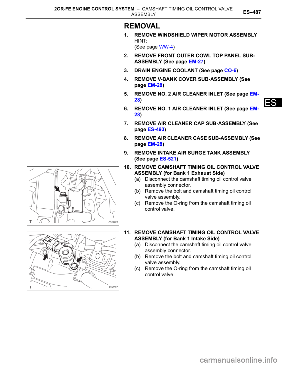
10. REMOVE CAMSHAFT TIMING OIL CONTROL VALVE
ASSEMBLY (for Bank 1 Exhaust Side)
(a) Disconnect the camshaft timing oil control valve
assembly connector.
(b) Remove the bolt and camshaft timing oil control
valve assembly.
(c) Remove the O-ring from the camshaft timing oil
control valve.
11. REMOVE CAMSHAFT TIMING OIL CONTROL VALVE
ASSEMBLY (for Bank 1 Intake Side)
(a) Disconnect the camshaft timing oil control valve
assembly connector.
(b) Remove the bolt and camshaft timing oil control
valve assembly.
(c) Remove the O-ring from the camshaft timing oil
control valve.
A135698
A135697
Page 881 of 3000
EM–762GR-FE ENGINE MECHANICAL – ENGINE UNIT
EM
DISASSEMBLY
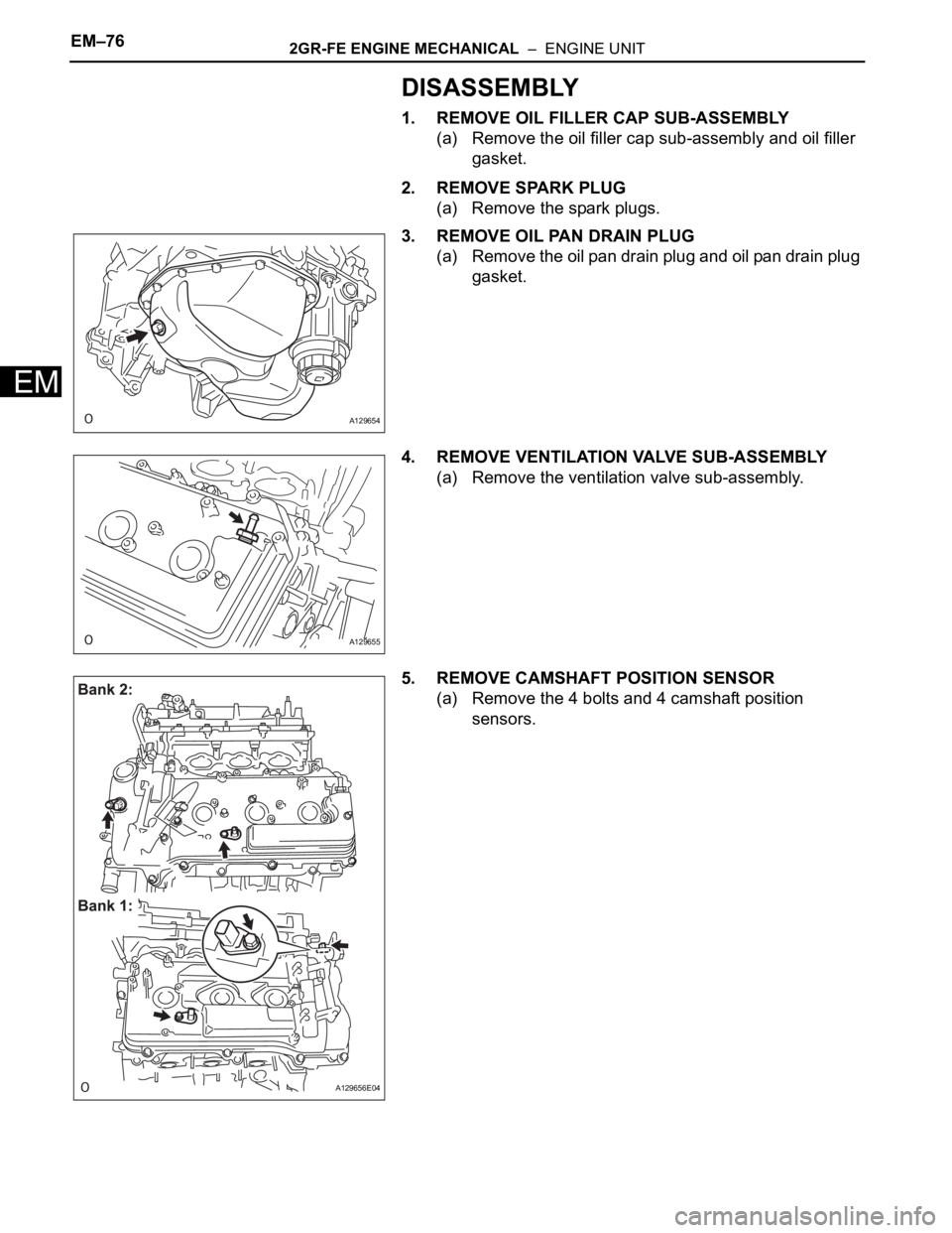
1. REMOVE OIL FILLER CAP SUB-ASSEMBLY
(a) Remove the oil filler cap sub-assembly and oil filler
gasket.
2. REMOVE SPARK PLUG
(a) Remove the spark plugs.
3. REMOVE OIL PAN DRAIN PLUG
(a) Remove the oil pan drain plug and oil pan drain plug
gasket.
4. REMOVE VENTILATION VALVE SUB-ASSEMBLY
(a) Remove the ventilation valve sub-assembly.
5. REMOVE CAMSHAFT POSITION SENSOR
(a) Remove the 4 bolts and 4 camshaft position
sensors.
A129654
A129655
A129656E04
Page 887 of 3000
EM–822GR-FE ENGINE MECHANICAL – ENGINE UNIT
EM
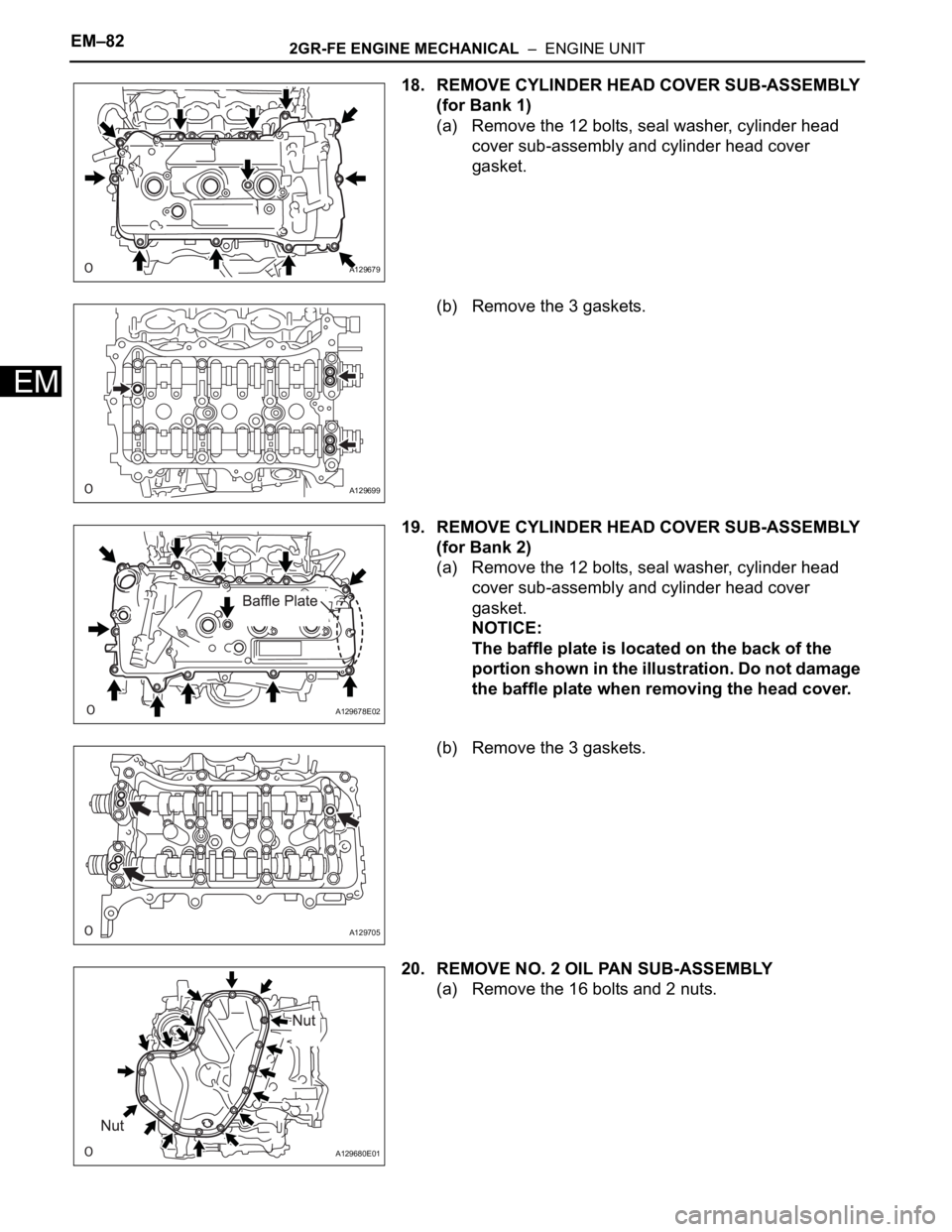
18. REMOVE CYLINDER HEAD COVER SUB-ASSEMBLY
(for Bank 1)
(a) Remove the 12 bolts, seal washer, cylinder head
cover sub-assembly and cylinder head cover
gasket.
(b) Remove the 3 gaskets.
19. REMOVE CYLINDER HEAD COVER SUB-ASSEMBLY
(for Bank 2)
(a) Remove the 12 bolts, seal washer, cylinder head
cover sub-assembly and cylinder head cover
gasket.
NOTICE:
The baffle plate is located on the back of the
portion shown in the illustration. Do not damage
the baffle plate when removing the head cover.
(b) Remove the 3 gaskets.
20. REMOVE NO. 2 OIL PAN SUB-ASSEMBLY
(a) Remove the 16 bolts and 2 nuts.
A129679
A129699
A129678E02
A129705
A129680E01
Page 888 of 3000
2GR-FE ENGINE MECHANICAL – ENGINE UNITEM–83
EM
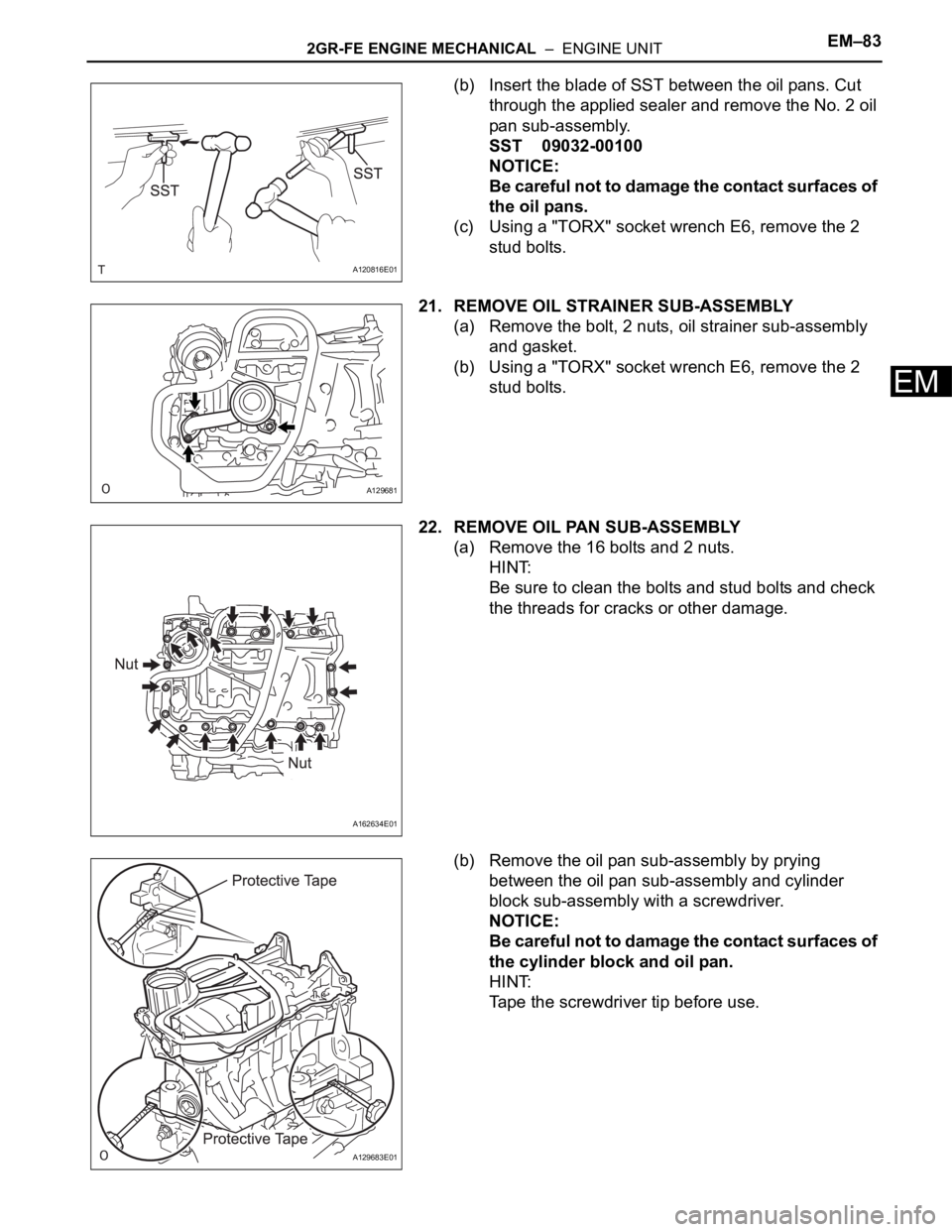
(b) Insert the blade of SST between the oil pans. Cut
through the applied sealer and remove the No. 2 oil
pan sub-assembly.
SST 09032-00100
NOTICE:
Be careful not to damage the contact surfaces of
the oil pans.
(c) Using a "TORX" socket wrench E6, remove the 2
stud bolts.
21. REMOVE OIL STRAINER SUB-ASSEMBLY
(a) Remove the bolt, 2 nuts, oil strainer sub-assembly
and gasket.
(b) Using a "TORX" socket wrench E6, remove the 2
stud bolts.
22. REMOVE OIL PAN SUB-ASSEMBLY
(a) Remove the 16 bolts and 2 nuts.
HINT:
Be sure to clean the bolts and stud bolts and check
the threads for cracks or other damage.
(b) Remove the oil pan sub-assembly by prying
between the oil pan sub-assembly and cylinder
block sub-assembly with a screwdriver.
NOTICE:
Be careful not to damage the contact surfaces of
the cylinder block and oil pan.
HINT:
Tape the screwdriver tip before use.
A120816E01
A129681
A162634E01
A129683E01
Page 889 of 3000
EM–842GR-FE ENGINE MECHANICAL – ENGINE UNIT
EM
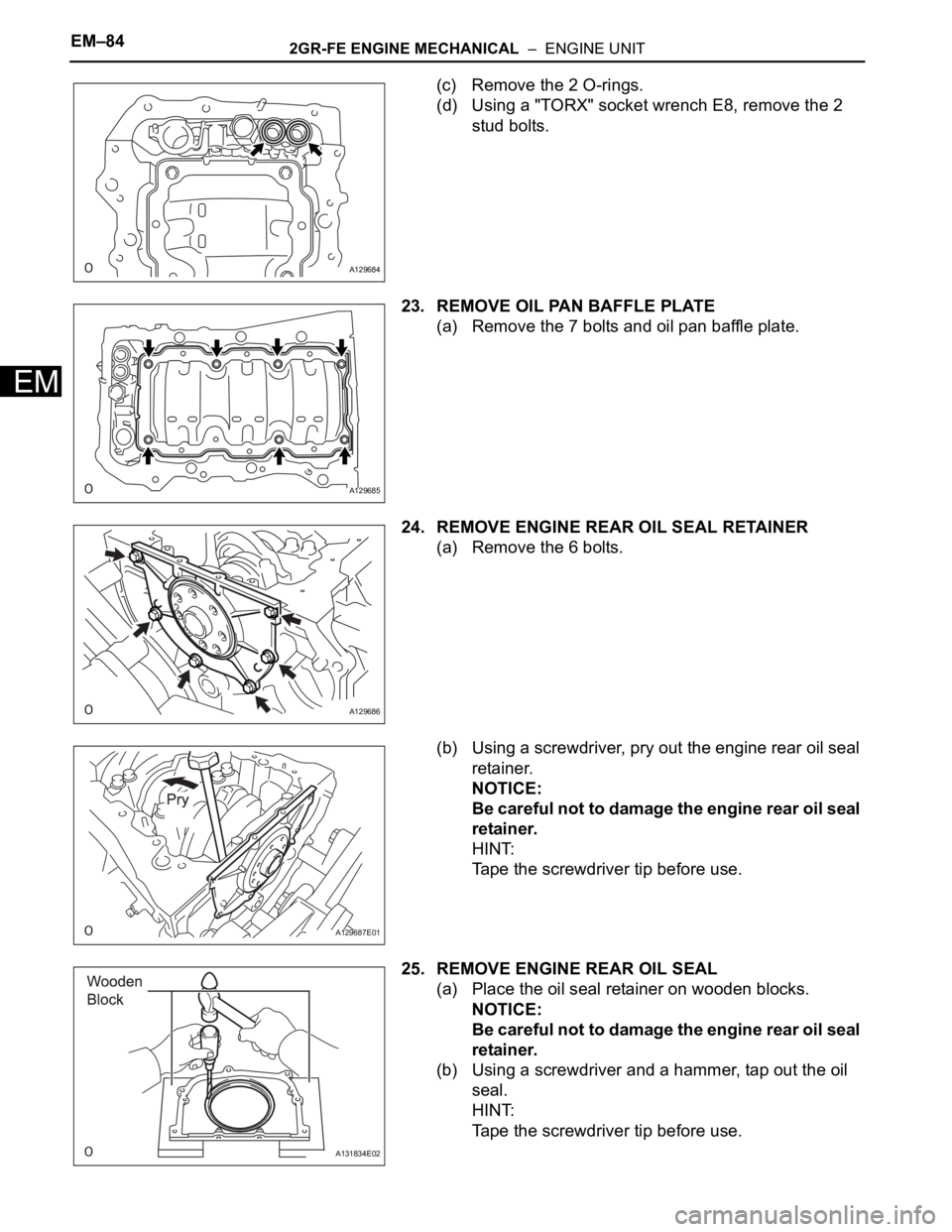
(c) Remove the 2 O-rings.
(d) Using a "TORX" socket wrench E8, remove the 2
stud bolts.
23. REMOVE OIL PAN BAFFLE PLATE
(a) Remove the 7 bolts and oil pan baffle plate.
24. REMOVE ENGINE REAR OIL SEAL RETAINER
(a) Remove the 6 bolts.
(b) Using a screwdriver, pry out the engine rear oil seal
retainer.
NOTICE:
Be careful not to damage the engine rear oil seal
retainer.
HINT:
Tape the screwdriver tip before use.
25. REMOVE ENGINE REAR OIL SEAL
(a) Place the oil seal retainer on wooden blocks.
NOTICE:
Be careful not to damage the engine rear oil seal
retainer.
(b) Using a screwdriver and a hammer, tap out the oil
seal.
HINT:
Tape the screwdriver tip before use.
A129684
A129685
A129686
A129687E01
A131834E02
Page 903 of 3000
EM–982GR-FE ENGINE MECHANICAL – ENGINE UNIT
EM
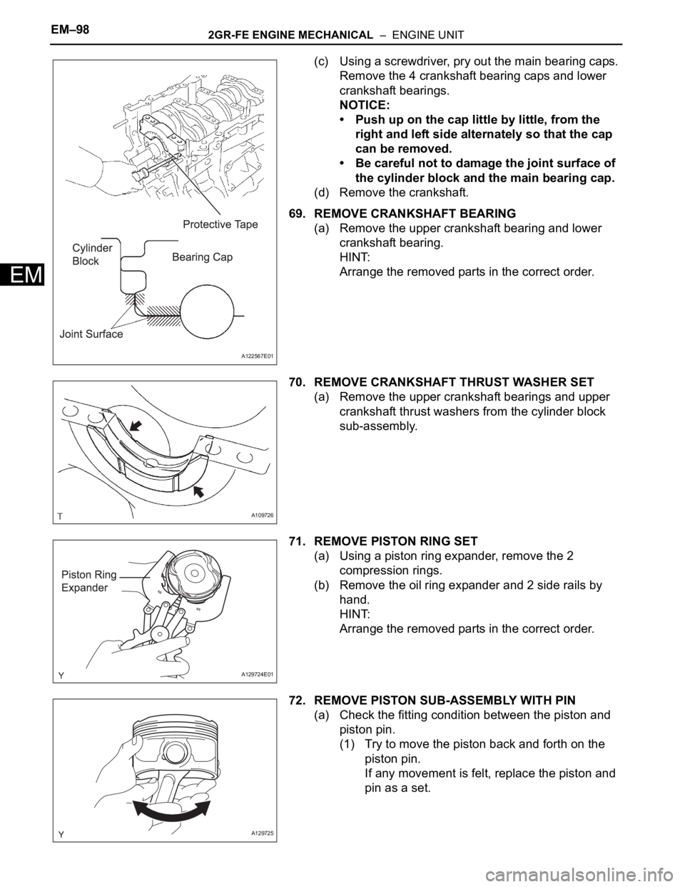
(c) Using a screwdriver, pry out the main bearing caps.
Remove the 4 crankshaft bearing caps and lower
crankshaft bearings.
NOTICE:
• Push up on the cap little by little, from the
right and left side alternately so that the cap
can be removed.
• Be careful not to damage the joint surface of
the cylinder block and the main bearing cap.
(d) Remove the crankshaft.
69. REMOVE CRANKSHAFT BEARING
(a) Remove the upper crankshaft bearing and lower
crankshaft bearing.
HINT:
Arrange the removed parts in the correct order.
70. REMOVE CRANKSHAFT THRUST WASHER SET
(a) Remove the upper crankshaft bearings and upper
crankshaft thrust washers from the cylinder block
sub-assembly.
71. REMOVE PISTON RING SET
(a) Using a piston ring expander, remove the 2
compression rings.
(b) Remove the oil ring expander and 2 side rails by
hand.
HINT:
Arrange the removed parts in the correct order.
72. REMOVE PISTON SUB-ASSEMBLY WITH PIN
(a) Check the fitting condition between the piston and
piston pin.
(1) Try to move the piston back and forth on the
piston pin.
If any movement is felt, replace the piston and
pin as a set.
A122567E01
A109726
A129724E01
A129725
Page 937 of 3000
EM–1282GR-FE ENGINE MECHANICAL – ENGINE UNIT
EM
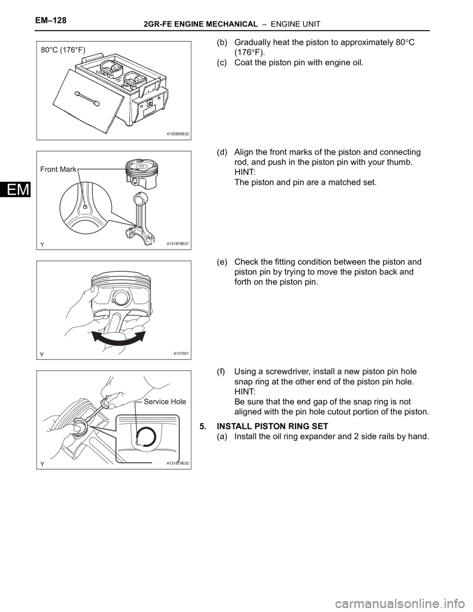
(b) Gradually heat the piston to approximately 80C
(176
F).
(c) Coat the piston pin with engine oil.
(d) Align the front marks of the piston and connecting
rod, and push in the piston pin with your thumb.
HINT:
The piston and pin are a matched set.
(e) Check the fitting condition between the piston and
piston pin by trying to move the piston back and
forth on the piston pin.
(f) Using a screwdriver, install a new piston pin hole
snap ring at the other end of the piston pin hole.
HINT:
Be sure that the end gap of the snap ring is not
aligned with the pin hole cutout portion of the piston.
5. INSTALL PISTON RING SET
(a) Install the oil ring expander and 2 side rails by hand.
A125895E02
A131878E01
A107551
A131879E02