2007 NISSAN TIIDA front
[x] Cancel search: frontPage 3264 of 5883

SQUEAK AND RATTLE TROUBLE DIAGNOSES
GW-5
< SYMPTOM DIAGNOSIS >
C
D
E
F
G
H
I
J
L
MA
B
GW
N
O
P
2. Trunk lid striker out of adjustment
3. The trunk lid torsion bars knocking together
4. A loose license plate or bracket
Most of these incidents can be repaired by adjusting, securing or insulating the item(s) or component(s) caus-
ing the noise.
SUNROOF/HEADLINING
Noises in the sunroof/headlining area can often be traced to one of the following:
1. Sunroof lid, rail, linkage or seals making a rattle or light knocking noise
2. Sun visor shaft shaking in the holder
3. Front or rear windshield touching headliner and squeaking
Again, pressing on the components to stop the noise while duplicating the conditions can isolate most of these
incidents. Repairs usually consist of insulating with felt cloth tape.
OVERHEAD CONSOLE (FRONT AND REAR)
Overhead console noises are often caused by the console panel clips not being engaged correctly. Most of
these incidents are repaired by pushing up on the console at the clip locations until the clips engage.
In addition look for:
1. Loose harness or harness connectors.
2. Front console map/reading lamp lense loose.
3. Loose screws at console attachment points.
SEATS
When isolating seat noise it's important to note the position the seat is in and the load placed on the seat when
the noise is present. These conditions should be duplicated when verifying and isolating the cause of the
noise.
Cause of seat noise include:
1. Headrest rods and holder
2. A squeak between the seat pad cushion and frame
3. The rear seatback lock and bracket
These noises can be isolated by moving or pressing on the suspected components while duplicating the con-
ditions under which the noise occurs. Most of these incidents can be repaired by repositioning the component
or applying urethane tape to the contact area.
UNDERHOOD
Some interior noise may be caused by components under the hood or on the engine wall. The noise is then
transmitted into the passenger compartment.
Causes of transmitted underhood noise include:
1. Any component mounted to the engine wall
2. Components that pass through the engine wall
3. Engine wall mounts and connectors
4. Loose radiator mounting pins
5. Hood bumpers out of adjustment
6. Hood striker out of adjustment
These noises can be difficult to isolate since they cannot be reached from the interior of the vehicle. The best
method is to secure, move or insulate one component at a time and test drive the vehicle. Also, engine RPM
or load can be changed to isolate the noise. Repairs can usually be made by moving, adjusting, securing, or
insulating the component causing the noise.
Page 3267 of 5883
GW-8
< PRECAUTION >
PRECAUTIONS
PRECAUTION
PRECAUTIONS
Precaution for Supplemental Restraint System (SRS) "AIR BAG" and "SEAT BELT
PRE-TENSIONER"
INFOID:0000000001716811
The Supplemental Restraint System such as “AIR BAG” and “SEAT BELT PRE-TENSIONER”, used along
with a front seat belt, helps to reduce the risk or severity of injury to the driver and front passenger for certain
types of collision. Information necessary to service the system safely is included in the SRS and SB section of
this Service Manual.
WARNING:
• To avoid rendering the SRS inoperative, which could increase the risk of personal injury or death in
the event of a collision which would result in air bag inflation, all maintenance must be performed by
an authorized NISSAN/INFINITI dealer.
Improper maintenance, including incorrect removal and installation of the SRS, can lead to personal
injury caused by unintentional activation of the system. For removal of Spiral Cable and Air Bag
Module, see the SRS section.
Do not use electrical test equipment on any circuit related to the SRS unless instructed to in this
Service Manual. SRS wiring harnesses can be identified by yellow and/or orange harnesses or har-
ness connectors.
Precaution for Procedure without Cowl Top CoverINFOID:0000000001716812
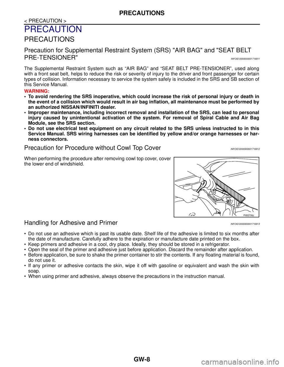
When performing the procedure after removing cowl top cover, cover
the lower end of windshield.
Handling for Adhesive and PrimerINFOID:0000000001716813
Do not use an adhesive which is past its usable date. Shelf life of the adhesive is limited to six months after
the date of manufacture. Carefully adhere to the expiration or manufacture date printed on the box.
Keep primers and adhesive in a cool, dry place. Ideally, they should be stored in a refrigerator.
Open the seal of the primer and adhesive just before application. Discard the remainder after application.
Before application, be sure to shake the primer container to stir the contents. If any floating material is found,
do not use it.
If any primer or adhesive contacts the skin, wipe it off with gasoline or equivalent and wash the skin with
soap.
When using primer and adhesive, always observe the precautions in the instruction manual.
PIIB3706J
Page 3269 of 5883
GW-10
< ON-VEHICLE REPAIR >
WINDSHIELD GLASS
ON-VEHICLE REPAIR
WINDSHIELD GLASS
Removal and InstallationINFOID:0000000001716818
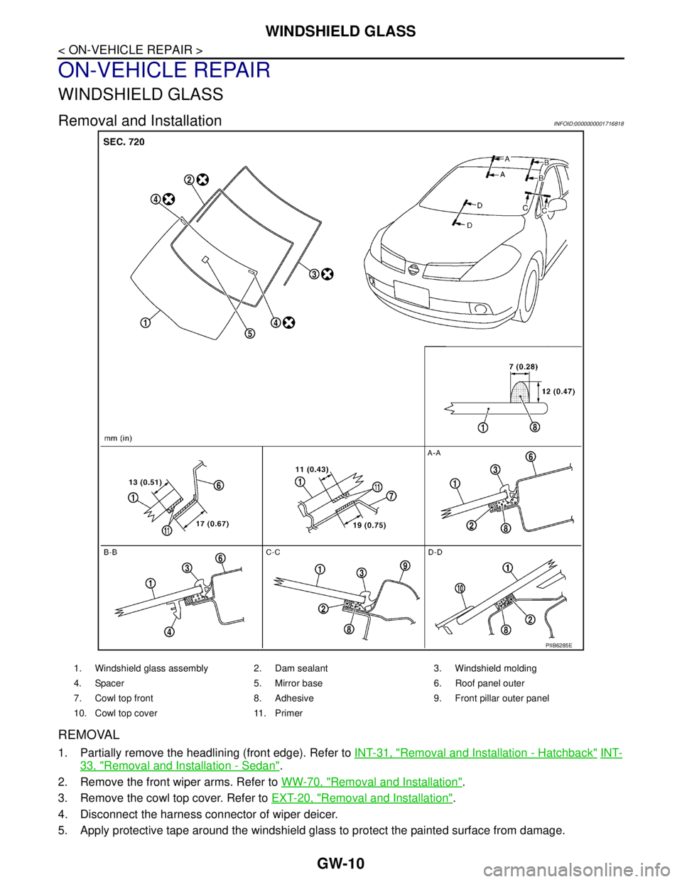
REMOVAL
1. Partially remove the headlining (front edge). Refer to INT-31, "Removal and Installation - Hatchback" INT-
33, "Removal and Installation - Sedan".
2. Remove the front wiper arms. Refer to WW-70, "
Removal and Installation".
3. Remove the cowl top cover. Refer to EXT-20, "
Removal and Installation".
4. Disconnect the harness connector of wiper deicer.
5. Apply protective tape around the windshield glass to protect the painted surface from damage.
PIIB6285E
1. Windshield glass assembly 2. Dam sealant 3. Windshield molding
4. Spacer 5. Mirror base 6. Roof panel outer
7. Cowl top front 8. Adhesive 9. Front pillar outer panel
10. Cowl top cover 11. Primer
Page 3271 of 5883
GW-12
< ON-VEHICLE REPAIR >
OPERA WINDOW GLASS
OPERA WINDOW GLASS
Removal and InstallationINFOID:0000000001716819
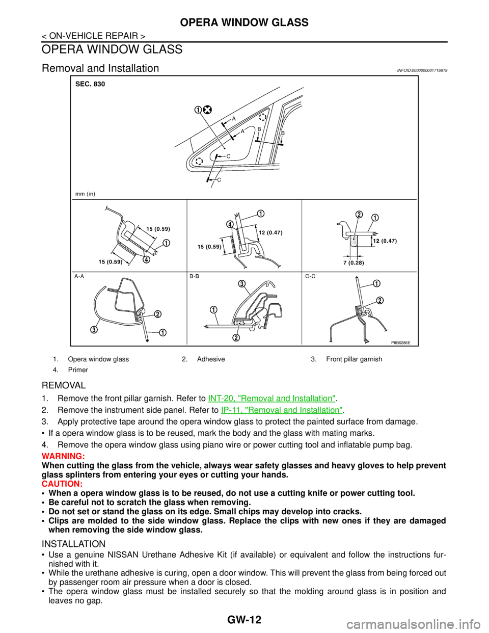
REMOVAL
1. Remove the front pillar garnish. Refer to INT-20, "Removal and Installation".
2. Remove the instrument side panel. Refer to IP-11, "
Removal and Installation".
3. Apply protective tape around the opera window glass to protect the painted surface from damage.
If a opera window glass is to be reused, mark the body and the glass with mating marks.
4. Remove the opera window glass using piano wire or power cutting tool and inflatable pump bag.
WARNING:
When cutting the glass from the vehicle, always wear safety glasses and heavy gloves to help prevent
glass splinters from entering your eyes or cutting your hands.
CAUTION:
When a opera window glass is to be reused, do not use a cutting knife or power cutting tool.
Be careful not to scratch the glass when removing.
Do not set or stand the glass on its edge. Small chips may develop into cracks.
Clips are molded to the side window glass. Replace the clips with new ones if they are damaged
when removing the side window glass.
INSTALLATION
Use a genuine NISSAN Urethane Adhesive Kit (if available) or equivalent and follow the instructions fur-
nished with it.
While the urethane adhesive is curing, open a door window. This will prevent the glass from being forced out
by passenger room air pressure when a door is closed.
The opera window glass must be installed securely so that the molding around glass is in position and
leaves no gap.
PIIB6286E
1. Opera window glass 2. Adhesive 3. Front pillar garnish
4. Primer
Page 3273 of 5883
GW-14
< ON-VEHICLE REPAIR >
FRONT DOOR GLASS AND REGULATOR
FRONT DOOR GLASS AND REGULATOR
Removal and InstallationINFOID:0000000001716843
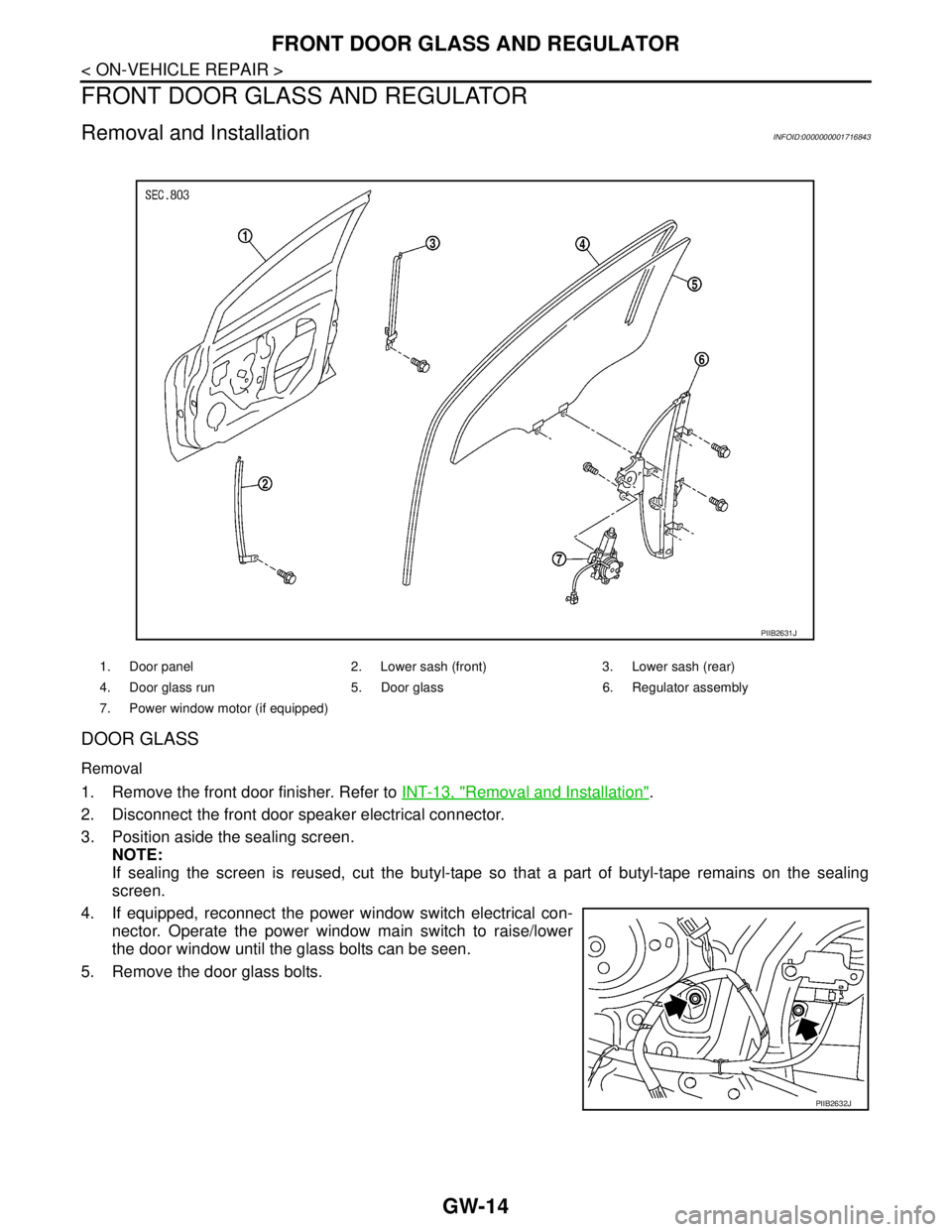
DOOR GLASS
Removal
1. Remove the front door finisher. Refer to INT-13, "Removal and Installation".
2. Disconnect the front door speaker electrical connector.
3. Position aside the sealing screen.
NOTE:
If sealing the screen is reused, cut the butyl-tape so that a part of butyl-tape remains on the sealing
screen.
4. If equipped, reconnect the power window switch electrical con-
nector. Operate the power window main switch to raise/lower
the door window until the glass bolts can be seen.
5. Remove the door glass bolts.
1. Door panel 2. Lower sash (front) 3. Lower sash (rear)
4. Door glass run 5. Door glass 6. Regulator assembly
7. Power window motor (if equipped)
PIIB2631J
PIIB2632J
Page 3274 of 5883
FRONT DOOR GLASS AND REGULATOR
GW-15
< ON-VEHICLE REPAIR >
C
D
E
F
G
H
I
J
L
MA
B
GW
N
O
P
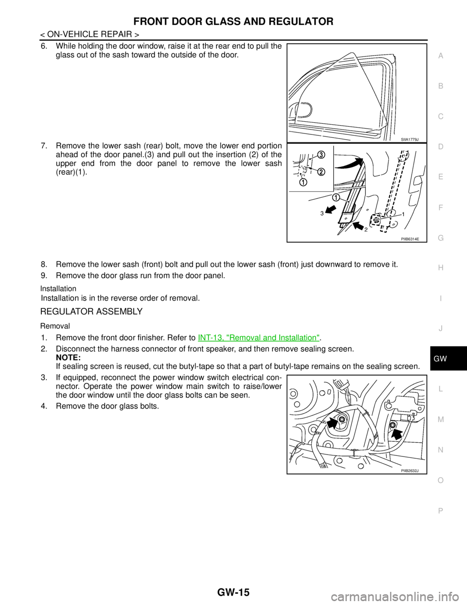
6. While holding the door window, raise it at the rear end to pull the
glass out of the sash toward the outside of the door.
7. Remove the lower sash (rear) bolt, move the lower end portion
ahead of the door panel.(3) and pull out the insertion (2) of the
upper end from the door panel to remove the lower sash
(rear)(1).
8. Remove the lower sash (front) bolt and pull out the lower sash (front) just downward to remove it.
9. Remove the door glass run from the door panel.
Installation
Installation is in the reverse order of removal.
REGULATOR ASSEMBLY
Removal
1. Remove the front door finisher. Refer to INT-13, "Removal and Installation".
2. Disconnect the harness connector of front speaker, and then remove sealing screen.
NOTE:
If sealing screen is reused, cut the butyl-tape so that a part of butyl-tape remains on the sealing screen.
3. If equipped, reconnect the power window switch electrical con-
nector. Operate the power window main switch to raise/lower
the door window until the door glass bolts can be seen.
4. Remove the door glass bolts.
SIIA1779J
PIIB6314E
PIIB2632J
Page 3275 of 5883
GW-16
< ON-VEHICLE REPAIR >
FRONT DOOR GLASS AND REGULATOR
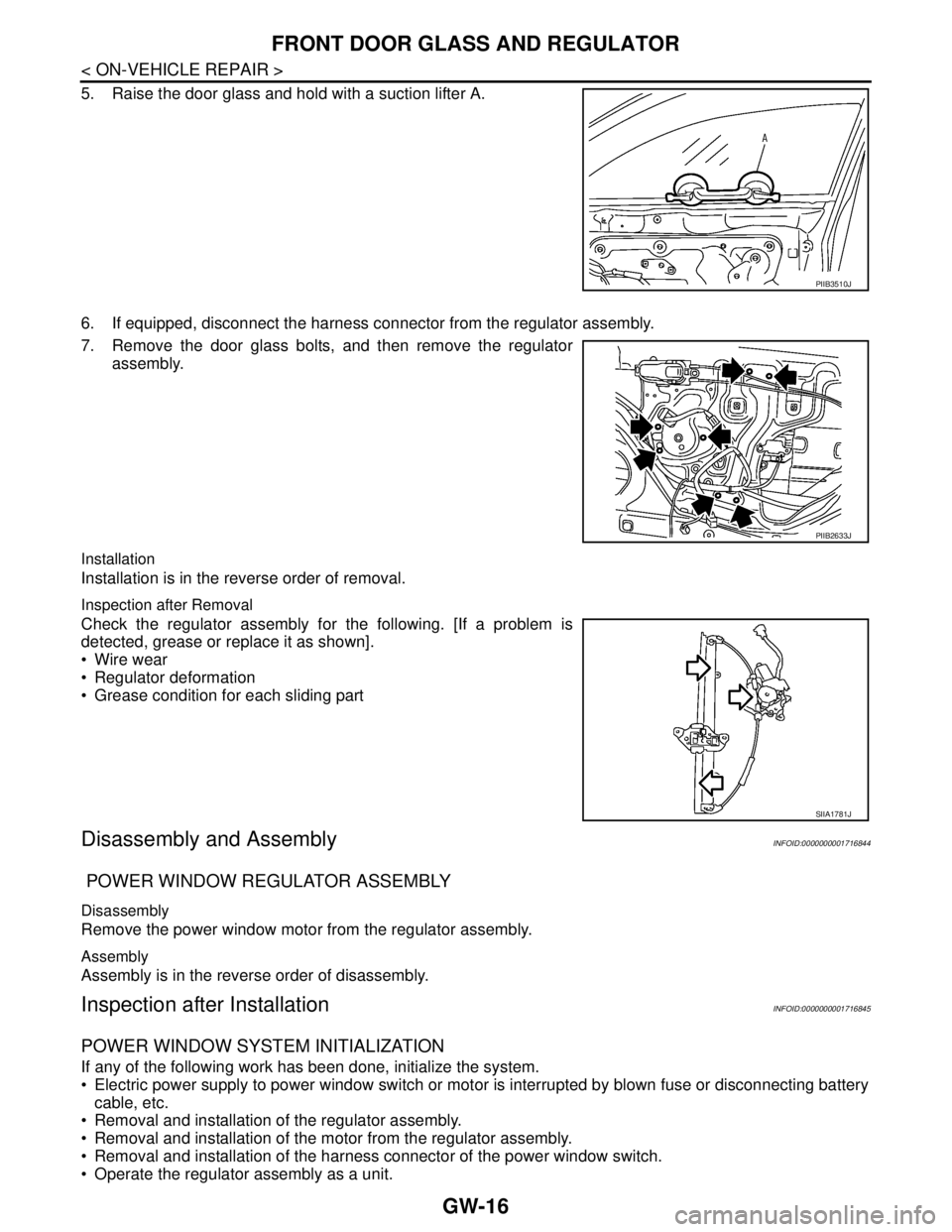
5. Raise the door glass and hold with a suction lifter A.
6. If equipped, disconnect the harness connector from the regulator assembly.
7. Remove the door glass bolts, and then remove the regulator
assembly.
Installation
Installation is in the reverse order of removal.
Inspection after Removal
Check the regulator assembly for the following. [If a problem is
detected, grease or replace it as shown].
Wire wear
Regulator deformation
Grease condition for each sliding part
Disassembly and AssemblyINFOID:0000000001716844
POWER WINDOW REGULATOR ASSEMBLY
Disassembly
Remove the power window motor from the regulator assembly.
Assembly
Assembly is in the reverse order of disassembly.
Inspection after InstallationINFOID:0000000001716845
POWER WINDOW SYSTEM INITIALIZATION
If any of the following work has been done, initialize the system.
Electric power supply to power window switch or motor is interrupted by blown fuse or disconnecting battery
cable, etc.
Removal and installation of the regulator assembly.
Removal and installation of the motor from the regulator assembly.
Removal and installation of the harness connector of the power window switch.
Operate the regulator assembly as a unit.
PIIB3510J
PIIB2633J
SIIA1781J
Page 3276 of 5883
FRONT DOOR GLASS AND REGULATOR
GW-17
< ON-VEHICLE REPAIR >
C
D
E
F
G
H
I
J
L
MA
B
GW
N
O
P
Removal and installation of the door glass.
Removal and installation of the door glass run.
Initialization
After installing each component to the vehicle, follow the steps below.
1. Disconnect the battery negative cable or disconnect power window switch's harness connector tempo-
rarily, then reconnect after at least 1 minute.
2. Turn ignition switch ON.
3. Open the window to its full width by operating the power window switch. (Exclude this procedure if the
window is already fully opened).
4. Move the power window switch in the up direction (auto close position) and hold. Keep holding the switch
even when window is completely closed, and then release after 3 seconds have passed.
5. Inspection of the anti-pinch system function.
NOTE:
Initialization may be cancelled with continuous opening and closing operation. In this case, initialize the
system.
INSPECT THE FUNCTION OF THE ANTI-PINCH SYSTEM
1. Fully open the door glass.
2. Place a wooden piece (wooden hammer handle, etc.) near the fully closed position.
3. Carry out fully closing operation with auto up switch.
Check that the glass reverses without pinching the wooden piece, is lowered approx.150 mm (5.91 in) or for
2 seconds and then stops.
The glass should not be raised with power window main switch while it is reversing or lowering.
CAUTION:
Use care to avoid being pinched during the inspection. Do not use a hand, etc. in place of the
wooden piece during the inspection.
Check that auto up function is normal before inspection, following the system initialization.
FITTING INSPECTION
Make sure the glass is securely fit into the glass run groove.
Lower the glass slightly [approx. 10 to 20 mm (0.39 to 0.79 in)] and make sure the clearance to the sash is
parallel. If the clearance between the glass and sash is not parallel, loosen the regulator bolts, guide rail
bolts, and the glass and guide rail bolts to correct the glass position.
Make sure the system is normal with raising and lowering the glass.