2007 NISSAN TIIDA front
[x] Cancel search: frontPage 3235 of 5883
IDENTIFICATION INFORMATION
GI-41
< FEATURES OF NEW MODEL >
C
D
E
F
G
H
I
J
K
L
MB
GI
N
O
P
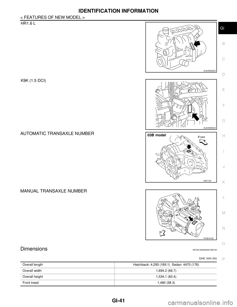
HR1.6 L
K9K (1.5 DCI)
AUTOMATIC TRANSAXLE NUMBER
MANUAL TRANSAXLE NUMBER
DimensionsINFOID:0000000001606152
Unit: mm (in)
ALAIA0002ZZ
ALAIA0003ZZ
SGI113A
PCIB1612E
Overall length Hatchback: 4,295 (169.1) Sedan: 4470 (176)
Overall width1,694.2 (66.7)
Overall height1,534.1 (60.4)
Front tread1,480 (58.3)
Page 3237 of 5883
PRECAUTIONS
GI-43
< PRECAUTION >
C
D
E
F
G
H
I
J
K
L
MB
GI
N
O
PPRECAUTION
PRECAUTIONS
DescriptionINFOID:0000000001606115
Observe the following precautions to ensure safe and proper servicing. These precautions are not
described in each individual section.
Precaution for Supplemental Restraint System (SRS) "AIR BAG" and "SEAT BELT
PRE-TENSIONER"
INFOID:0000000001606116
The Supplemental Restraint System such as “AIR BAG” and “SEAT BELT PRE-TENSIONER”, used along
with a front seat belt, helps to reduce the risk or severity of injury to the driver and front passenger for certain
types of collision. Information necessary to service the system safely is included in the SR and SB section of
this Service Manual.
WARNING:
To avoid rendering the SRS inoperative, which could increase the risk of personal injury or death in
the event of a collision which would result in air bag inflation, all maintenance must be performed by
an authorized NISSAN/INFINITI dealer.
Improper maintenance, including incorrect removal and installation of the SRS, can lead to personal
injury caused by unintentional activation of the system. For removal of Spiral Cable and Air Bag
Module, see the SR section.
Do not use electrical test equipment on any circuit related to the SRS unless instructed to in this
Service Manual. SRS wiring harnesses can be identified by yellow and/or orange harnesses or har-
ness connectors.
Precaution Necessary for Steering Wheel Rotation After Battery Disconnect
INFOID:0000000001606117
NOTE:
This Procedure is applied only to models with Intelligent Key system and NATS (NISSAN ANTI-THEFT SYS-
TEM).
Remove and install all control units after disconnecting both battery cables with the ignition knob in the
″LOCK″ position.
Always use CONSULT-II to perform self-diagnosis as a part of each function inspection after finishing work.
If DTC is detected, perform trouble diagnosis according to self-diagnostic results.
For models equipped with the Intelligent Key system and NATS, an electrically controlled steering lock mech-
anism is adopted on the key cylinder.
For this reason, if the battery is disconnected or if the battery is discharged, the steering wheel will lock and
steering wheel rotation will become impossible.
If steering wheel rotation is required when battery power is interrupted, follow the procedure below before
starting the repair operation.
OPERATION PROCEDURE
1. Connect both battery cables.
NOTE:
Supply power using jumper cables if battery is discharged.
2. Use the Intelligent Key or mechanical key to turn the ignition switch to the ″ACC″ position. At this time, the
steering lock will be released.
3. Disconnect both battery cables. The steering lock will remain released and the steering wheel can be
rotated.
4. Perform the necessary repair operation.
5. When the repair work is completed, return the ignition switch to the ″LOCK″ position before connecting
the battery cables. (At this time, the steering lock mechanism will engage.)
6. Perform a self-diagnosis check of all control units using CONSULT-II.
Page 3242 of 5883
GI-48
< PRECAUTION >
LIFTING POINT
LIFTING POINT
Special Service ToolINFOID:0000000001606131
CAUTION:
Every time the vehicle is lifted up, maintain the complete vehicle curb condition.
Since the vehicle's center of gravity changes when removing main parts on the front side (engine,
transmission, suspension etc.), support a jack up point on the rear side garage jack with a mission
jack or equivalent.
Since the vehicle's center of gravity changes when removing main parts on the rear side (rear axle,
suspension, etc.), support a jack up point on the front side garage jack with a mission jack or equiv-
alent.
Be careful not to smash or do not do anything that would affect piping parts.
Garage Jack and Safety Stand and 2-Pole LiftINFOID:0000000001606132
WARNING:
Park the vehicle on a level surface when using the jack. Make sure to avoid damaging pipes, tubes,
etc. under the vehicle.
Never get under the vehicle while it is supported only by the jack. Always use safety stands when
you have to get under the vehicle.
Place wheel chocks at both front and back of the wheels on the ground.
When lifting the vehicle, open the lift arms as wide as possible and ensure that the front and rear of
the vehicle are well balanced.
When setting the lift arm, do not allow the arm to contact the brake tubes, brake cable, fuel lines and
sill spoiler.
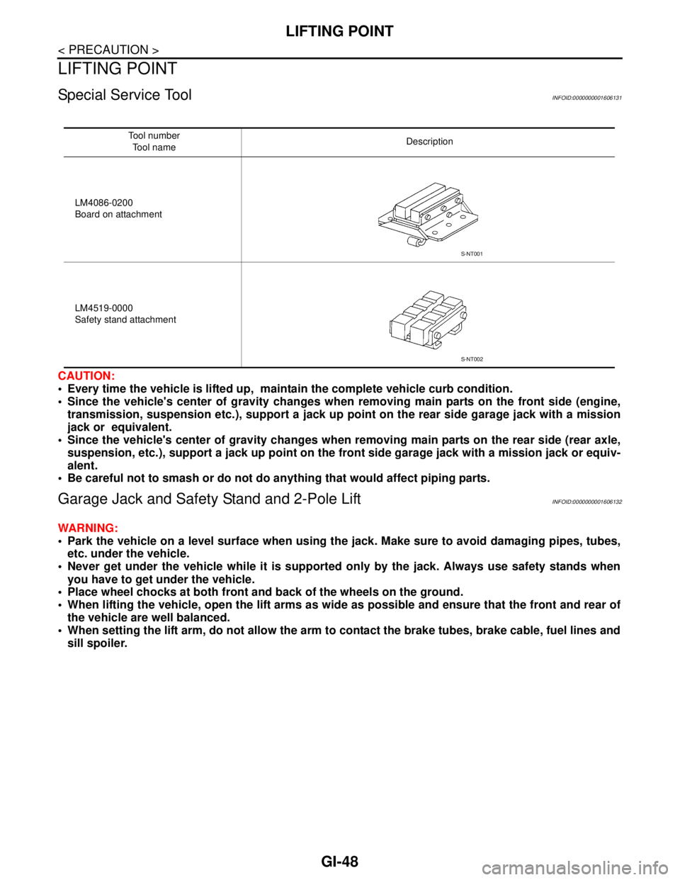
Tool number
Tool nameDescription
LM4086-0200
Board on attachment
LM4519-0000
Safety stand attachment
S-NT001
S-NT002
Page 3243 of 5883
LIFTING POINT
GI-49
< PRECAUTION >
C
D
E
F
G
H
I
J
K
L
MB
GI
N
O
P
CAUTION:
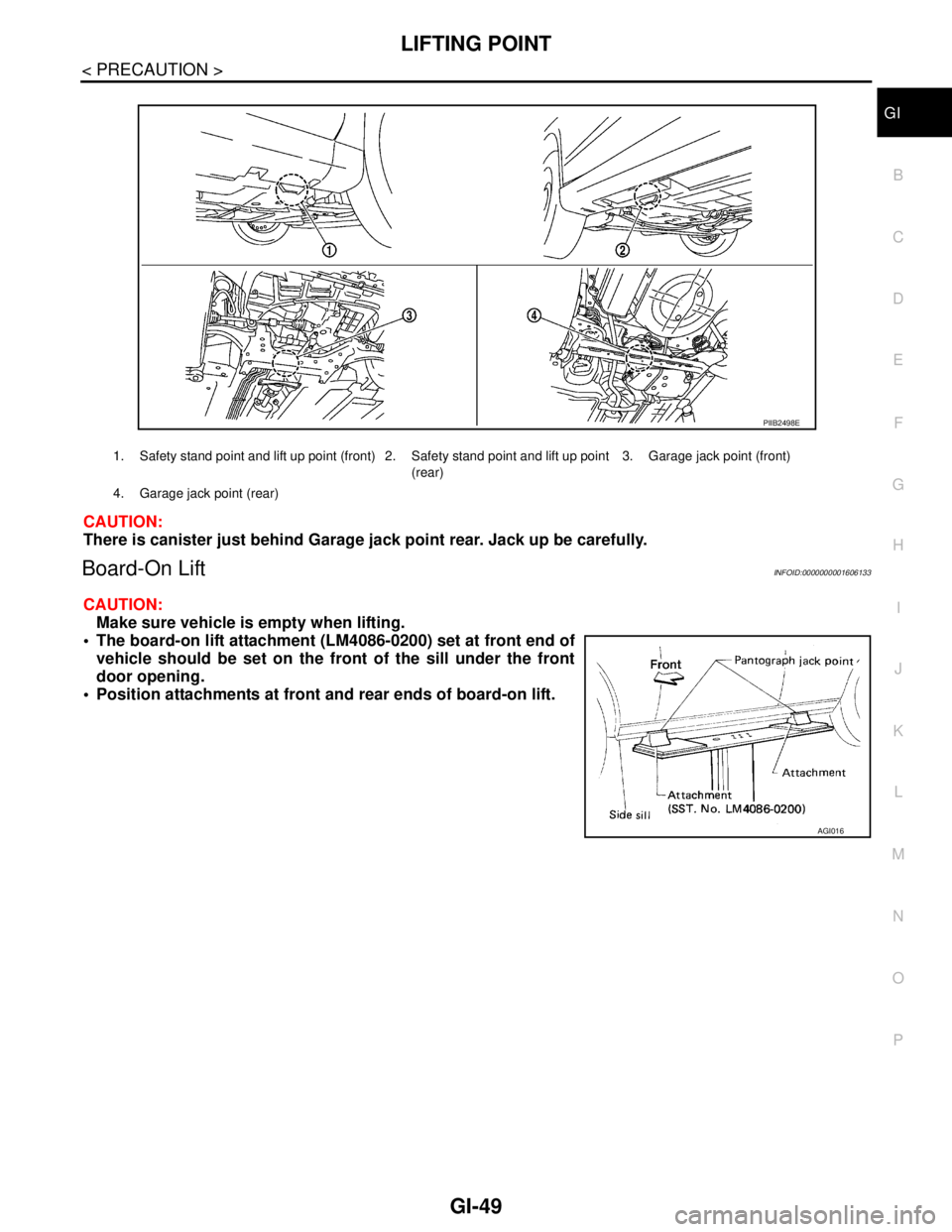
There is canister just behind Garage jack point rear. Jack up be carefully.
Board-On LiftINFOID:0000000001606133
CAUTION:
Make sure vehicle is empty when lifting.
The board-on lift attachment (LM4086-0200) set at front end of
vehicle should be set on the front of the sill under the front
door opening.
Position attachments at front and rear ends of board-on lift.
1. Safety stand point and lift up point (front) 2. Safety stand point and lift up point
(rear)3. Garage jack point (front)
4. Garage jack point (rear)
PIIB2498E
AGI016
Page 3244 of 5883
GI-50
< PRECAUTION >
TOW TRUCK TOWING
TOW TRUCK TOWING
Tow Truck TowingINFOID:0000000001606140
CAUTION:
All applicable local laws regarding the towing operation must be obeyed.
It is necessary to use proper towing equipment to avoid possible damage to the vehicle during tow-
ing operation. Towing is in accordance with Towing Procedure Manual at dealer.
Always attach safety chains before towing.
When towing, make sure that the transmission, steering system and power train are in good order. If
any unit is damaged, dollies must be used.
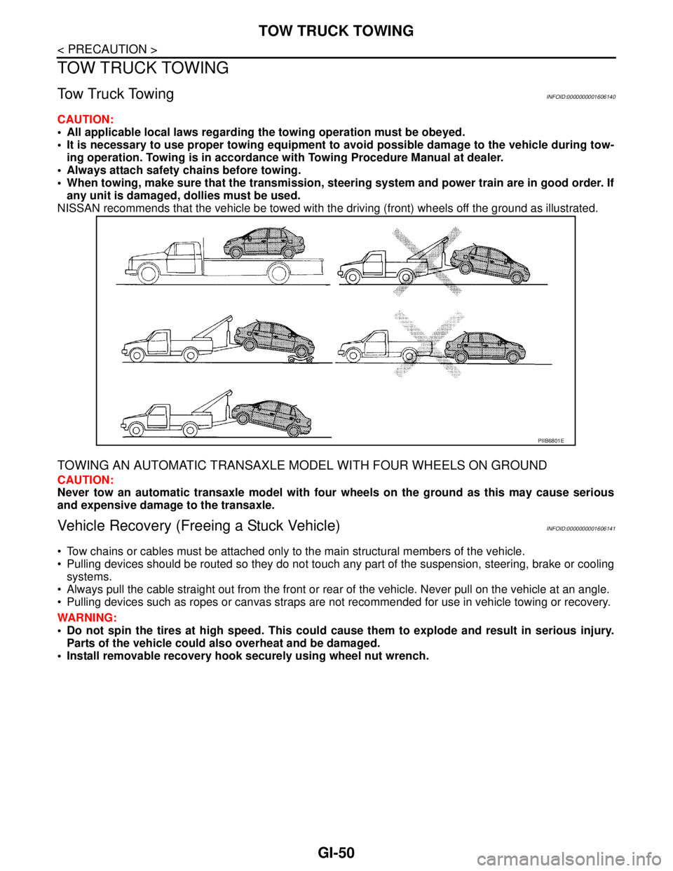
NISSAN recommends that the vehicle be towed with the driving (front) wheels off the ground as illustrated.
TOWING AN AUTOMATIC TRANSAXLE MODEL WITH FOUR WHEELS ON GROUND
CAUTION:
Never tow an automatic transaxle model with four wheels on the ground as this may cause serious
and expensive damage to the transaxle.
Vehicle Recovery (Freeing a Stuck Vehicle)INFOID:0000000001606141
Tow chains or cables must be attached only to the main structural members of the vehicle.
Pulling devices should be routed so they do not touch any part of the suspension, steering, brake or cooling
systems.
Always pull the cable straight out from the front or rear of the vehicle. Never pull on the vehicle at an angle.
Pulling devices such as ropes or canvas straps are not recommended for use in vehicle towing or recovery.
WARNING:
Do not spin the tires at high speed. This could cause them to explode and result in serious injury.
Parts of the vehicle could also overheat and be damaged.
Install removable recovery hook securely using wheel nut wrench.
PIIB6801E
Page 3257 of 5883
CONSULT-III CHECKING SYSTEM
GI-63
< BASIC INSPECTION >
C
D
E
F
G
H
I
J
K
L
MB
GI
N
O
PCONSULT-III CHECKING SYSTEM
DescriptionINFOID:0000000001691472
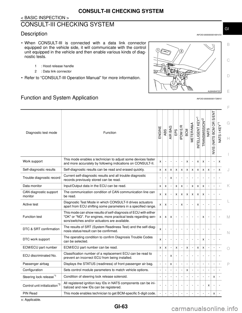
When CONSULT-III is connected with a data link connector
equipped on the vehicle side, it will communicate with the control
unit equipped in the vehicle and then enable various kinds of diag-
nostic tests.
Refer to “CONSULT-III Operation Manual” for more information.
Function and System ApplicationINFOID:0000000001728915
x: Applicable.1 : Hood release handle
2 : Data link connector
ALBIA0047ZZ
Diagnostic test mode Function
ENGINE
ABS
AIR BAG
EPS
IPDM E/R
BCM
METER/M&A
INTELLIGENT KEY*
1
TRANSMISSION*
2
NATS
NVIS (NATS BCM OR S/ENT
NATS I-KEY
*1
Work supportThis mode enables a technician to adjust some devices faster
and more accurately by following indications on CONSULT-II.x----x-xx--x
Self-diagnostic results Self-diagnostic results can be read and erased quickly. xxxxxxxxxx - x
Trouble diagnostic recordCurrent self-diagnostic results and all trouble diagnostic
records previously stored can be read.--x---------
Data monitor Input/Output data in the ECU can be read. x x - x x - x x x - - -
CAN diagnostic support
monitorThe communication condition of CAN communication line can
be read.xx - xxxxxx - - -
Active testDiagnostic Test Mode in which CONSULT-II drives actuators
apart from ECU shifting some parameters in a specified range.xx--x--x----
Function testThis mode can show results of self-diagnosis of ECU with either
"OK" or "NG". For engines, more practical tests regarding sen-
sors/switches and/or actuators are available.xxx-----x---
DTC & SRT confirmationThe results of SRT (System Readiness Test) and the self-diag-
nosis status/result can be confirmed.x-----------
DTC work supportThe operating condition to confirm Diagnosis Trouble Codes
can be selected.x-------x---
ECM/ECU part number ECM/ECU part number can be read. x x - x - x - x x - - -
ECU discriminated No.Classification number of a replacement ECU can be read to
prevent an incorrect ECU from being installed.--x---------
Passenger airbag Displays the STATUS (readiness) of front passenger air bag. --x---------
Configuration Sets control module parameters to match vehicle options. -----x------
Steering lock release
*1Condition of steering lock release solenoid. ----------x-
Control unit initialization
*3All registered ignition key IDs in NATS components can be ini-
tialized and new IDs can be registered.---------x--
PIN Read This mode enables technician to get BCM-specific 5-digit code.----------x-
Page 3260 of 5883

GW-1
BODY EXTERIOR, DOORS, ROOF & VEHICLE SECURITY
C
D
E
F
G
H
I
J
L
M
SECTION GW
A
B
GW
N
O
P
CONTENTS
GLASS & WINDOW SYSTEM
SYMPTOM DIAGNOSIS ...............................2
SQUEAK AND RATTLE TROUBLE DIAG-
NOSES ................................................................
2
Work Flow .................................................................2
Generic Squeak and Rattle Troubleshooting ............4
Diagnostic Worksheet ...............................................6
PRECAUTION ...............................................8
PRECAUTIONS ...................................................8
Precaution for Supplemental Restraint System
(SRS) "AIR BAG" and "SEAT BELT PRE-TEN-
SIONER" ...................................................................
8
Precaution for Procedure without Cowl Top Cover ......8
Handling for Adhesive and Primer ............................8
PREPARATION ............................................9
PREPARATION ...................................................9
Commercial Service Tool ..........................................9
ON-VEHICLE REPAIR .................................10
WINDSHIELD GLASS .......................................10
Removal and Installation .........................................10
OPERA WINDOW GLASS ................................12
Removal and Installation .........................................12
FRONT DOOR GLASS AND REGULATOR .....14
Removal and Installation .........................................14
Disassembly and Assembly .....................................16
Inspection after Installation ......................................16
REAR WINDOW GLASS AND MOLDING ........18
Removal and Installation .........................................18
REAR DOOR GLASS AND REGULATOR .......21
Removal and Installation .........................................21
Disassembly and Assembly .....................................23
Inspection after Installation ......................................23
Page 3263 of 5883

GW-4
< SYMPTOM DIAGNOSIS >
SQUEAK AND RATTLE TROUBLE DIAGNOSES
68370-4B000: 15×25 mm (0.59×0.98 in) pad/68239-13E00: 5 mm (0.20 in) wide tape roll. The following
materials not found in the kit can also be used to repair squeaks and rattles.
UHMW (TEFLON) TAPE
Insulates where slight movement is present. Ideal for instrument panel applications.
SILICONE GREASE
Used instead of UHMW tape that will be visible or not fit.
Note: Will only last a few months.
SILICONE SPRAY
Use when grease cannot be applied.
DUCT TAPE
Use to eliminate movement.
CONFIRM THE REPAIR
Confirm that the cause of a noise is repaired by test driving the vehicle. Operate the vehicle under the same
conditions as when the noise originally occurred. Refer to the notes on the Diagnostic Worksheet.
Generic Squeak and Rattle TroubleshootingINFOID:0000000001716816
Refer to Table of Contents for specific component removal and installation information.
INSTRUMENT PANEL
Most incidents are caused by contact and movement between:
1. The cluster lid A and instrument panel
2. Acrylic lens and combination meter housing
3. Instrument panel to front pillar garnish
4. Instrument panel to windshield
5. Instrument panel mounting pins
6. Wiring harnesses behind the combination meter
7. A/C defroster duct and duct joint
These incidents can usually be located by tapping or moving the components to duplicate the noise or by
pressing on the components while driving to stop the noise. Most of these incidents can be repaired by apply-
ing felt cloth tape or silicone spray (in hard to reach areas). Urethane pads can be used to insulate wiring har-
ness.
CAUTION:
Do not use silicone spray to isolate a squeak or rattle. If you saturate the area with silicone, you will
not be able to recheck the repair.
CENTER CONSOLE
Components to pay attention to include:
1. Shifter assembly cover to finisher
2. A/C control unit and cluster lid C
3. Wiring harnesses behind audio and A/C control unit
The instrument panel repair and isolation procedures also apply to the center console.
DOORS
Pay attention to the:
1. Finisher and inner panel making a slapping noise
2. Inside handle escutcheon to door finisher
3. Wiring harnesses tapping
4. Door striker out of alignment causing a popping noise on starts and stops
Tapping or moving the components or pressing on them while driving to duplicate the conditions can isolate
many of these incidents. You can usually insulate the areas with felt cloth tape or insulator foam blocks from
the NISSAN Squeak and Rattle Kit (J-43980) to repair the noise.
TRUNK
Trunk noises are often caused by a loose jack or loose items put into the trunk by the owner.
In addition look for:
1. Trunk lid bumpers out of adjustment