2007 NISSAN TIIDA Engine Control
[x] Cancel search: Engine ControlPage 4327 of 5883

MWI-20
< FUNCTION DIAGNOSIS >
METER SYSTEM
Unit Description
Combination meter Controls the information display according to the signal received from each unit.
Fuel level sensor unit Refer to MWI-29, "
Description".
ECMTransmits the following signals to the combination meter via CAN communication line.
Engine speed signal Fuel consumption monitor signal
ABS actuator and electric unit
(control unit)Transmits the vehicle speed signal to the combination meter via CAN communication line.
Ambient sensor Refer to MWI-34, "
Description".
Oil level sensor Refer to MWI-32, "
Description".
Page 4332 of 5883

MWI
DTC B2205 VEHICLE SPEED CIRCUIT
MWI-25
< COMPONENT DIAGNOSIS >
C
D
E
F
G
H
I
J
K
L
MB A
O
P
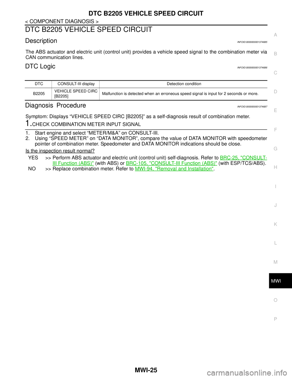
DTC B2205 VEHICLE SPEED CIRCUIT
DescriptionINFOID:0000000001374685
The ABS actuator and electric unit (control unit) provides a vehicle speed signal to the combination meter via
CAN communication lines.
DTC LogicINFOID:0000000001374686
Diagnosis ProcedureINFOID:0000000001374687
Symptom: Displays “VEHICLE SPEED CIRC [B2205]” as a self-diagnosis result of combination meter.
1.CHECK COMBINATION METER INPUT SIGNAL
1. Start engine and select “METER/M&A” on CONSULT-III.
2. Using “SPEED METER” on “DATA MONITOR”, compare the value of DATA MONITOR with speedometer
pointer of combination meter. Speedometer and DATA MONITOR indications should be close.
Is the inspection result normal?
YES >> Perform ABS actuator and electric unit (control unit) self-diagnosis. Refer to BRC-25, "CONSULT-
III Function (ABS)" (with ABS) or BRC-105, "CONSULT-III Function (ABS)" (with ESP/TCS/ABS).
NO >> Replace combination meter. Refer to MWI-94, "
Removal and Installation".
DTC CONSULT-III display Detection condition
B2205VEHICLE SPEED CIRC
[B2205]Malfunction is detected when an erroneous speed signal is input for 2 seconds or more.
Page 4362 of 5883

MWI
BCM (BODY CONTROL MODULE)
MWI-55
< ECU DIAGNOSIS >
C
D
E
F
G
H
I
J
K
L
MB A
O
P
BCM (BODY CONTROL MODULE)
Reference ValueINFOID:0000000001713119
VALUES ON THE DIAGNOSIS TOOL
Monitor Item Condition Value/Status
AIR COND SWA/C switch OFF OFF
A/C switch ON ON
AUT LIGHT SYSOutside of the room is dark OFF
Outside of the room is bright ON
AUTO LIGHT SWLighting switch OFF OFF
Lighting switch AUTO ON
BACK DOOR SWBack door closed OFF
Back door opened ON
BATTERY VOLT
NOTE:
Diesel engine models
onlyIgnition switch ONApproximately the same as power
supply voltage
CDL LOCK SWDoor lock/unlock switch does not operate OFF
Press door lock/unlock switch to the LOCK side ON
CDL UNLOCK SWDoor lock/unlock switch does not operate OFF
Press door lock/unlock switch to the UNLOCK side ON
DOOR SW-ASPassenger door closed OFF
Passenger door opened ON
DOOR SW-DRDriver door closed OFF
Driver door opened ON
DOOR SW-RLRear LH door closed OFF
Rear LH door opened ON
DOOR SW-RRRear RH door closed OFF
Rear RH door opened ON
ELEC PWR CUT
NOTE:
Diesel engine models
onlyEngine runningFan switch ON (when engine coolant is
cool)
NOTE:
Depending on the ambient tempera-
ture, battery voltage, etc.OFF
The current status maintained with the
signal from ECM received.FREEZ
Fan switch OFF
Fan switch ON after engine warming
UP
NOTE:
Depending on the engine coolant
temperature, ambient temperature,
battery voltage, etc.INHBT
ENG COOLNT T
NOTE:
Diesel engine models
onlyEngine runningApproximately the same as engine
water temperature
ENGINE RPM
NOTE:
Diesel engine models
onlyEngine runningApproximately the same as tachom-
eter reading
Page 4363 of 5883

MWI-56
< ECU DIAGNOSIS >
BCM (BODY CONTROL MODULE)
ENGINE RUNEngine stopped OFF
Engine running ON
ENGINE STATUS
NOTE:
Diesel engine models
onlyEngine stopped STOP
While the engine stalls STALL
Engine running RUN
At engine cranking CRA
FA N O N S I GFan switch OFF OFF
Fan switch ON ON
FR FOG SWFront fog lamp switch OFF OFF
Front fog lamp switch ON ON
FR WASHER SWFront washer switch OFF OFF
Front washer switch ON ON
FR WIPER LOWFront wiper switch OFF OFF
Front wiper switch LO ON
FR WIPER HIFront wiper switch OFF OFF
Front wiper switch HI ON
FR WIPER INTFront wiper switch OFF OFF
Front wiper switch INT ON
FR WIPER STOPAny position other than front wiper stop position OFF
Front wiper stop position ON
HAZARD SWWhen hazard switch is not pressed OFF
When hazard switch is pressed ON
LIGHT SW 1STLighting switch OFF OFF
Lighting switch 1st ON
H/L SW POSHeadlamp switch OFF OFF
Headlamp switch 1st ON
HI BEAM SWHigh beam switch OFF OFF
High beam switch HI ON
HOOD SWClose the hood
NOTE:
Vehicles without theft warning system are OFF-fixedOFF
Open the hood ON
H/L WASH SWNOTE:
The item is indicated, but not monitoredOFF
IGN ON SWIgnition switch OFF or ACC OFF
Ignition switch ON ON
IGN SW CANIgnition switch OFF or ACC OFF
Ignition switch ON ON
INT VOLUME Wiper intermittent dial is in a dial position 1 - 7 1 - 7
I-KEY LOCK
1LOCK button of Intelligent Key is not pressed OFF
LOCK button of Intelligent Key is pressed ON
I-KEY UNLOCK
1UNLOCK button of Intelligent Key is not pressed OFF
UNLOCK button of Intelligent Key is pressed ON
KEY SW
2Mechanical key is removed from key cylinder OFF
Mechanical key is inserted to key cylinder ON Monitor Item Condition Value/Status
Page 4364 of 5883

MWI
BCM (BODY CONTROL MODULE)
MWI-57
< ECU DIAGNOSIS >
C
D
E
F
G
H
I
J
K
L
MB A
O
P
1: With Intelligent Key
2: With remote keyless entry system
3: HatchbackKEYLESS LOCK
2LOCK button of key fob is not pressed OFF
LOCK button of key fob is pressed ON
KEYLESS UNLOCK
2UNLOCK button of key fob is not pressed OFF
UNLOCK button of key fob is pressed ON
LIT-SEN FAILLight & rain sensor is in normal condition OK
Light & rain sensor is with internal error NOTOK
OIL PRESS SW Ignition switch OFF or ACC
Engine runningOFF
Ignition switch ON ON
OUT SIDE TEMP
NOTE:
Diesel engine modelsIgnition switch ONApproximately the same as outside
air temperature
PASSING SWOther than lighting switch PASS OFF
Lighting switch PASS ON
PUSH SW
1Return to ignition switch to LOCK position OFF
Press ignition switch ON
REAR DEF SWRear window defogger switch OFF OFF
Rear window defogger switch ON ON
RKE LOCK AND
UNLOCK
2NOTE:
The item is indicated, but not monitoredOFF
ON
RR FOG SWRear fog lamp switch OFF OFF
Rear fog lamp switch ON ON
RR WASHER SW
3Rear washer switch OFF OFF
Rear washer switch ON ON
RR WIPER INT
3Rear wiper switch OFF OFF
Rear wiper switch INT ON
RR WIPER ON
3 Rear wiper switch OFF OFF
Rear wiper switch ON ON
RR WIPER STOP
3Rear wiper stop position OFF
Other than rear wiper stop position ON
TAIL LAMP SWLighting switch OFF OFF
Lighting switch 1ST ON
TRNK OPNR SWWhen back door opener switch is not pressed OFF
When back door opener switch is pressed ON
TURN SIGNAL LTurn signal switch OFF OFF
Turn signal switch LH ON
TURN SIGNAL RTurn signal switch OFF OFF
Turn signal switch RH ON
UNLOCK WITH DRNOTE:
The item is indicated, but not monitoredOFF
ON
VEHICLE SPEED While driving Equivalent to speedometer reading Monitor Item Condition Value/Status
Page 4385 of 5883

MWI-78
< ECU DIAGNOSIS >
IPDM E/R (INTELLIGENT POWER DISTRIBUTION MODULE ENGINE ROOM)
Te r m i n a lWire
colorSignal nameSignal
input/
outputMeasuring condition
Reference value
(Approx.) Ignition
switchOperation or condition
1 R Battery power supply Input OFF — Battery voltage
2 G Battery power supply Input OFF — Battery voltage
3 Y ECM Relay Output —Ignition switch ON or START Battery voltage
Ignition switch OFF or ACC 0V
4 G ECM relay Output —Ignition switch ON or START Battery voltage
Ignition switch OFF or ACC 0V
6GRDaytime light relay
controlInput ON Daytime light system active. Less than battery voltage
Daytime light system inactive. Battery voltage
7 G ECM relay control Input —Ignition switch ON or START 0V
Ignition switch OFF or ACC Battery voltage
8GThrottle control motor
relayOutput —Ignition switch ON or START Battery voltage
Ignition switch OFF or ACC 0V
11 W A/C compressor OutputON or
STARTA/C switch ON or defrost A/C
switchBattery voltage
A/C switch OFF or defrost A/C
switch0V
12 OIgnition switch sup-
plied powerInput —OFF or ACC 0V
ON or START Battery voltage
14BR
(M/T)
R
(A/T)Fuse 49 Output —Ignition switch ON or START Battery voltage
Ignition switch OFF or ACC 0V
15 V Fuse 50 Output —Ignition switch ON or START Battery voltage
Ignition switch OFF or ACC 0V
16 SB Fuse 51 Output —Ignition switch ON or START Battery voltage
Ignition switch OFF or ACC 0V
19 R Starter motor Output START — Battery voltage
20L
(with
A/C)
LG
(with-
out A/
C)Cooling fan relay-1 Output —Conditions correct for cooling
fan low operation.Battery voltage
Conditions not correct for
cooling fan low operation.0V
21 WIgnition switch START
signalInput START — Battery voltage
22 G Battery power supply Input — — Battery voltage
23 L Cooling fan relay-2 Input —Conditions correct for cooling
fan high operationBattery voltage
Conditions not correct for
cooling fan high operation0V
24 Y Cooling fan relay-3 Output —Conditions correct for cooling
fan high operationBattery voltage
Conditions not correct for
cooling fan high operation0V
27 BR
Tail lamp relay (park-
ing lamps)Output — Lighting switch in 2nd position Battery voltage
Page 4386 of 5883

MWI
IPDM E/R (INTELLIGENT POWER DISTRIBUTION MODULE ENGINE ROOM)
MWI-79
< ECU DIAGNOSIS >
C
D
E
F
G
H
I
J
K
L
MB A
O
P
29 PTail lamp relay (park-
ing lamps)Output — Lighting switch in 2nd position Battery voltage
30 R Fuse 54 Output —Ignition switch ON or START Battery voltage
Ignition switch OFF or ACC 0V
31 O Fuse 55 Output —Ignition switch ON or START Battery voltage
Ignition switch OFF or ACC 0V
32 LWiper high speed sig-
nalOutputON or
STARTWiper switchOFF, LO, INT 0V
HI Battery voltage
33 YWiper low speed sig-
nalOutputON or
STARTWiper switchOFF 0V
LO or INT Battery voltage
35 BRStarter relay (inhibit
switch)InputON or
STARTSelector lever in "P" or "N"
(CVT or A/T) or clutch pedal
depressed (M/T)Battery voltage
Selector lever any other posi-
tion (CVT or A/T) or clutch
pedal released (M/T)0V
36 BR Fuel pump relay Output —Ignition switch ON or START Battery voltage
Ignition switch OFF or ACC 0V
37 G Oil pressure switch InputON or
STARTEngine running and oil pres-
sure within specificationBattery voltage
Engine not running or oil pres-
sure below specification0V
38 R Wiper auto stop signal InputON or
STARTWipers not in park position Battery voltage
Wipers in park position 0V
39 B Ground Input — — 0V
40 P CAN-L — ON — —
41 L CAN-H — ON — —
46 YThrottle control motor
relay controlInput —Ignition switch ON or START 0V
Ignition switch OFF or ACC Battery voltage
47 GRFuel pump relay con-
trolInput —Ignition switch ON or START 0V
Ignition switch OFF or ACC Battery voltage
50 V Front fog lamp (LH)Output ON or
STARTLighting
switch must
be in the 2ND
position
(LOW beam
is ON) and
the front fog
lamp switchOFF 0V
ON Battery voltage
51 W Front fog lamp (RH) OutputON or
STARTLighting
switch must
be in the 2ND
position
(LOW beam
is ON) and
the front fog
lamp switchOFF 0V
ON Battery voltage
52 LLH Low beam head-
lampOutput — Lighting switch in 2nd position Battery voltage Te r m i n a lWire
colorSignal name
Signal
input/
outputMeasuring condition
Reference value
(Approx.) Ignition
switchOperation or condition
Page 4391 of 5883

MWI-84
< ECU DIAGNOSIS >
IPDM E/R (INTELLIGENT POWER DISTRIBUTION MODULE ENGINE ROOM)
Fail Safe
INFOID:0000000001713129
CAN COMMUNICATION CONTROL
When CAN communication with ECM and BCM is impossible, IPDM E/R performs fail-safe control. After CAN
communication recovers normally, it also returns to normal control.
If No CAN Communication Is Available With ECM
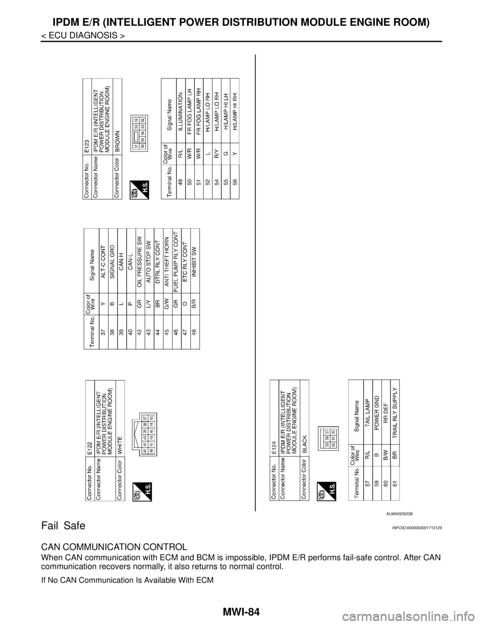
ALMIA0252GB