Page 3131 of 5883
DOOR OUTSIDE MOLDING
EXT-27
< ON-VEHICLE REPAIR >
C
D
E
F
G
H
I
J
L
MA
B
EXT
N
O
P
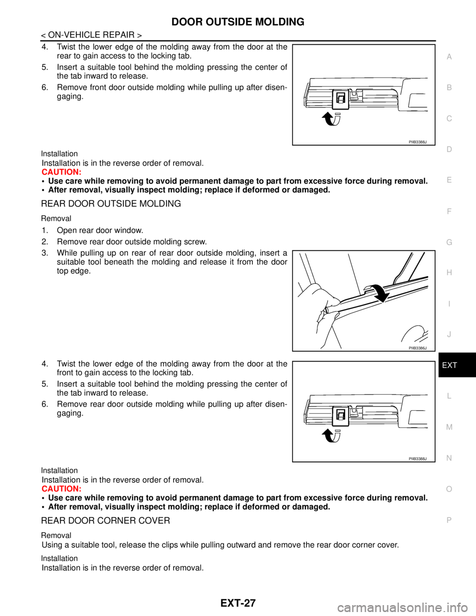
4. Twist the lower edge of the molding away from the door at the
rear to gain access to the locking tab.
5. Insert a suitable tool behind the molding pressing the center of
the tab inward to release.
6. Remove front door outside molding while pulling up after disen-
gaging.
Installation
Installation is in the reverse order of removal.
CAUTION:
Use care while removing to avoid permanent damage to part from excessive force during removal.
After removal, visually inspect molding; replace if deformed or damaged.
REAR DOOR OUTSIDE MOLDING
Removal
1. Open rear door window.
2. Remove rear door outside molding screw.
3. While pulling up on rear of rear door outside molding, insert a
suitable tool beneath the molding and release it from the door
top edge.
4. Twist the lower edge of the molding away from the door at the
front to gain access to the locking tab.
5. Insert a suitable tool behind the molding pressing the center of
the tab inward to release.
6. Remove rear door outside molding while pulling up after disen-
gaging.
Installation
Installation is in the reverse order of removal.
CAUTION:
Use care while removing to avoid permanent damage to part from excessive force during removal.
After removal, visually inspect molding; replace if deformed or damaged.
REAR DOOR CORNER COVER
Removal
Using a suitable tool, release the clips while pulling outward and remove the rear door corner cover.
Installation
Installation is in the reverse order of removal.
PIIB3388J
PIIB3386J
PIIB3388J
Page 3132 of 5883
EXT-28
< ON-VEHICLE REPAIR >
CENTER MUD GUARD
CENTER MUD GUARD
Removal and InstallationINFOID:0000000001568937
REMOVAL
1. Remove center mud guard clips (C205), front and rear.
2. Remove center mud guard bolts at bottom edge and release double-faced adhesive tape from body side.
3. Open front and rear doors, then using a suitable tool, detach the clips (C101) and remove the center mud
guard from the body side.
4. Release the sill cover cap clips, then remove sill cover cap.
INSTALLATION
Installation is in the reverse order of removal.
NOTE:
Always replace double-faced adhesive tape on back of center mud guard when installing.
Do not wash vehicle within 24 hours after installation.
1. Sill cover cap 2. Center mud guard 3. Double-faced adhesive tape
A. Clip C205 Clip C101⇐Vehicle front
AWKIA0099ZZ
Page 3135 of 5883
FAX-1
TRANSMISSION & DRIVELINE
C
E
F
G
H
I
J
K
L
M
SECTION FA X
A
B
FA X
N
O
P
CONTENTS
FRONT AXLE
PRECAUTION ...............................................2
PRECAUTIONS ...................................................2
Caution ......................................................................2
PREPARATION ............................................3
PREPARATION ...................................................3
Special Service Tool .................................................3
Commercial Service Tool ..........................................3
SYMPTOM DIAGNOSIS ...............................4
NOISE, VIBRATION AND HARSHNESS
(NVH) TROUBLESHOOTING .............................
4
NVH Troubleshooting Chart ......................................4
ON-VEHICLE MAINTENANCE .....................5
FRONT WHEEL HUB AND KNUCKLE ..............5
On-Vehicle Inspection and Service ...........................5
FRONT DRIVE SHAFT ........................................6
On-Vehicle Inspection and Service ...........................6
REMOVAL AND INSTALLATION ................7
FRONT WHEEL HUB AND KNUCKLE .............7
Removal and Installation ..........................................7
FRONT DRIVE SHAFT .....................................10
Removal and Installation (Left Side) ........................10
Removal and Installation (Right Side) .....................11
DISASSEMBLY AND ASSEMBLY ..............14
FRONT DRIVE SHAFT .....................................14
Disassembly and Assembly (Left Side) ...................14
Disassembly and Assembly (Right Side) .................19
SERVICE DATA AND SPECIFICATIONS
(SDS) ............................................................
26
SERVICE DATA AND SPECIFICATIONS
(SDS) .................................................................
26
Drive Shaft ...............................................................26
Dynamic Damper .....................................................26
Page 3138 of 5883
FAX-4
< SYMPTOM DIAGNOSIS >
NOISE, VIBRATION AND HARSHNESS (NVH) TROUBLESHOOTING
SYMPTOM DIAGNOSIS
NOISE, VIBRATION AND HARSHNESS (NVH) TROUBLESHOOTING
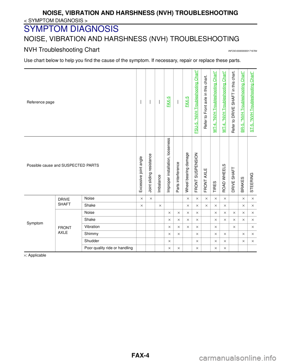
NVH Troubleshooting ChartINFOID:0000000001716784
Use chart below to help you find the cause of the symptom. If necessary, repair or replace these parts.
×: ApplicableReference page
—
—
—
FA X - 5—
FA X - 5
FSU-5, "
NVH Troubleshooting Chart
"
Refer to Front axle in this chart.
WT-4, "
NVH Troubleshooting Chart
"
WT-4, "
NVH Troubleshooting Chart
"
Refer to DRIVE SHAFT in this chart.
BR-5, "
NVH Troubleshooting Chart
"
ST-5, "
NVH Troubleshooting Chart
"
Possible cause and SUSPECTED PARTS
Excessive joint angle
Joint sliding resistance
Imbalance
Improper installation, looseness
Parts interference
Wheel bearing damage
FRONT SUSPENSION
FRONT AXLE
TIRES
ROAD WHEELS
DRIVE SHAFT
BRAKES
STEERING
SymptomDRIVE
SHAFTNoise×× ××××× ××
Shake× × ××××× ××
FRONT
AXLENoise×××× ×××××
Shake×××× ×××××
Vibration×××××××
Shimmy×××××××
Shudder× × ×× ××
Poor quality ride or handling×××××
Page 3139 of 5883
FRONT WHEEL HUB AND KNUCKLE
FAX-5
< ON-VEHICLE MAINTENANCE >
C
E
F
G
H
I
J
K
L
MA
B
FA X
N
O
P
ON-VEHICLE MAINTENANCE
FRONT WHEEL HUB AND KNUCKLE
On-Vehicle Inspection and ServiceINFOID:0000000001716786
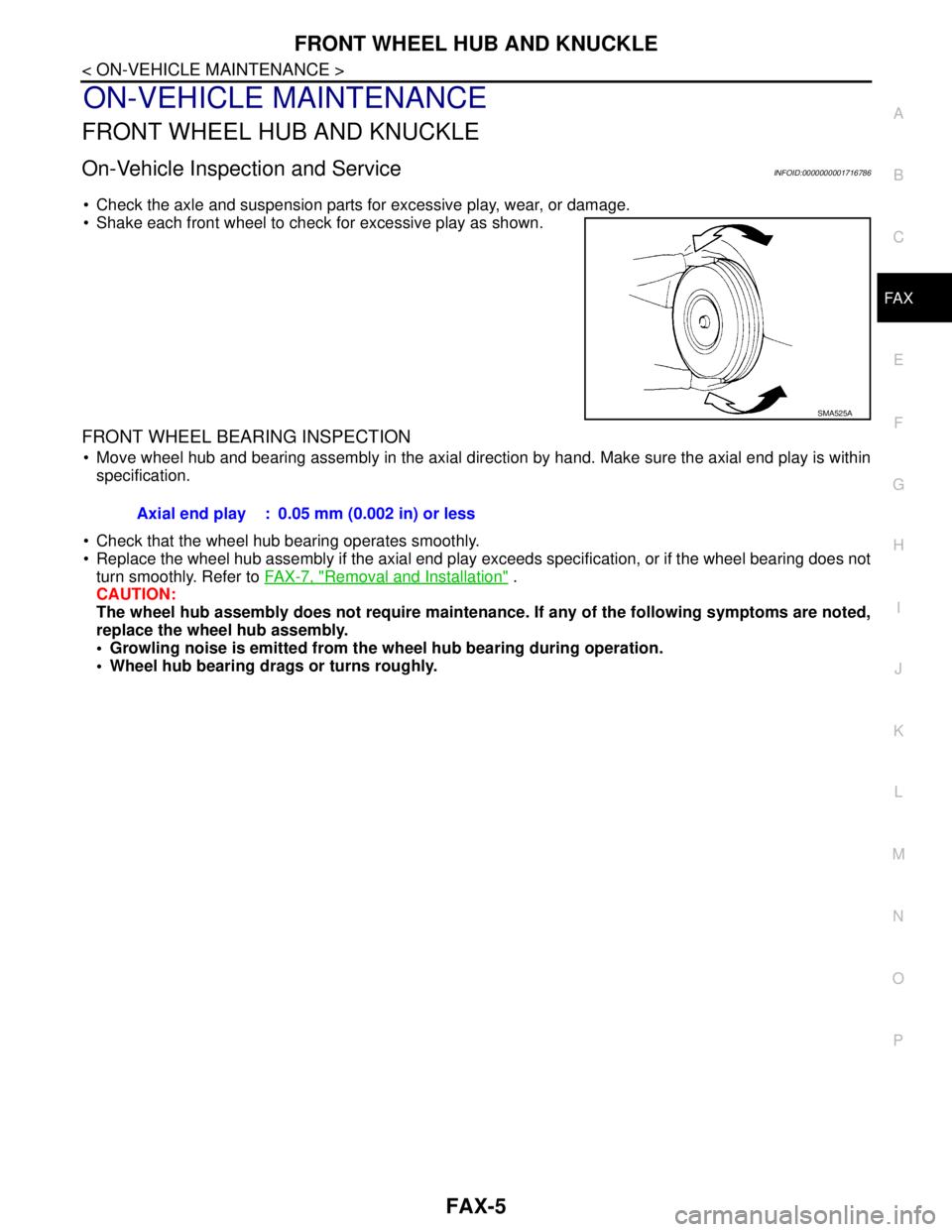
Check the axle and suspension parts for excessive play, wear, or damage.
Shake each front wheel to check for excessive play as shown.
FRONT WHEEL BEARING INSPECTION
Move wheel hub and bearing assembly in the axial direction by hand. Make sure the axial end play is within
specification.
Check that the wheel hub bearing operates smoothly.
Replace the wheel hub assembly if the axial end play exceeds specification, or if the wheel bearing does not
turn smoothly. Refer to FAX-7, "
Removal and Installation" .
CAUTION:
The wheel hub assembly does not require maintenance. If any of the following symptoms are noted,
replace the wheel hub assembly.
• Growling noise is emitted from the wheel hub bearing during operation.
Wheel hub bearing drags or turns roughly.
SMA525A
Axial end play : 0.05 mm (0.002 in) or less
Page 3140 of 5883
FAX-6
< ON-VEHICLE MAINTENANCE >
FRONT DRIVE SHAFT
FRONT DRIVE SHAFT
On-Vehicle Inspection and ServiceINFOID:0000000001716790
Check drive shaft mounting point and joint for looseness and other damage.
Check boot for cracks and other damage.
Replace or repair components as necessary. Refer to FAX-10, "
Removal and Installation (Left Side)" , FA X - 11 ,
"Removal and Installation (Right Side)" , FAX-14, "Disassembly and Assembly (Left Side)" or FAX-19, "Disas-
sembly and Assembly (Right Side)" .
CAUTION:
Replace entire drive shaft assembly when noise or vibration occur from drive shaft.
Page 3141 of 5883
FRONT WHEEL HUB AND KNUCKLE
FAX-7
< REMOVAL AND INSTALLATION >
C
E
F
G
H
I
J
K
L
MA
B
FA X
N
O
P
REMOVAL AND INSTALLATION
FRONT WHEEL HUB AND KNUCKLE
Removal and InstallationINFOID:0000000001716789
COMPONENT
REMOVAL
1. Remove wheel and tire using power tool. Refer to WT-6, "Rotation" .
2. Without disassembling the hydraulic lines, remove the torque member bolts using power tool. Then repo-
sition the torque member and brake caliper assembly aside with wire. Refer to BR-25, "
Removal and
Installation of Brake Caliper Assembly" .
CAUTION:
Do not depress brake pedal while brake caliper is removed.
3. Put alignment marks on disc rotor and wheel hub and bearing
assembly, then remove disc rotor.
4. Remove wheel sensor from steering knuckle. Refer to BRC-182, "
Removal and Installation" .
CAUTION:
Do not pull on wheel sensor harness.
1. Drive shaft 2. Steering knuckle 3. Splash guard
4. Wheel hub and bearing assembly 5. Cotter pin
WDIA0366E
SDIA1480E
Page 3142 of 5883
FAX-8
< REMOVAL AND INSTALLATION >
FRONT WHEEL HUB AND KNUCKLE
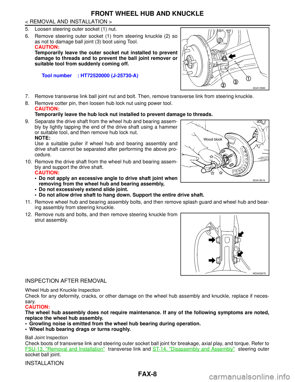
5. Loosen steering outer socket (1) nut.
6. Remove steering outer socket (1) from steering knuckle (2) so
as not to damage ball joint (3) boot using Tool.
CAUTION:
Temporarily leave the outer socket nut installed to prevent
damage to threads and to prevent the ball joint remover or
suitable tool from suddenly coming off.
7. Remove transverse link ball joint nut and bolt. Then, remove transverse link from steering knuckle.
8. Remove cotter pin, then loosen hub lock nut using power tool.
CAUTION:
Temporarily leave the hub lock nut installed to prevent damage to threads.
9. Separate the drive shaft from the wheel hub and bearing assem-
bly by lightly tapping the end of the drive shaft using a hammer
or suitable tool, and then remove hub lock nut.
NOTE:
Use a suitable puller if wheel hub and bearing assembly and
drive shaft cannot be separated after performing the above pro-
cedure.
10. Remove the drive shaft from the wheel hub and bearing assem-
bly and support the drive shaft.
CAUTION:
Do not apply an excessive angle to drive shaft joint when
removing from the wheel hub and bearing assembly,
Do not excessively extend slide joint.
Do not allow drive shaft to hang down. Support the entire drive shaft.
11. Remove wheel hub and bearing assembly bolts, and then remove splash guard and wheel hub and bear-
ing assembly from steering knuckle.
12. Remove nuts and bolts, and then remove steering knuckle from
strut assembly.
INSPECTION AFTER REMOVAL
Wheel Hub and Knuckle Inspection
Check for any deformity, cracks, or other damage on the wheel hub assembly and knuckle, replace if neces-
sary.
CAUTION:
The wheel hub assembly does not require maintenance. If any of the following symptoms are noted,
replace the wheel hub assembly.
Growling noise is emitted from the wheel hub bearing during operation.
Wheel hub bearing drags or turns roughly.
Ball Joint Inspection
Check boots of transverse link and steering outer socket ball joint for breakage, axial play, and torque. Refer to
FSU-13, "
Removal and Installation" transverse link and ST-14, "Disassembly and Assembly" steering outer
socket ball joint.
INSTALLATION
Tool number : HT72520000 (J-25730-A)
SGIA1298E
SDIA1821E
WDIA0367E