2007 NISSAN TIIDA Engine Control
[x] Cancel search: Engine ControlPage 3035 of 5883
EXL-34
< COMPONENT DIAGNOSIS >
HEADLAMP (HI) CIRCUIT
Is the measurement value normal?
YES >> GO TO 4
NO >> GO TO 3
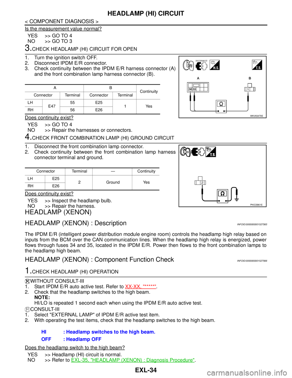
3.CHECK HEADLAMP (HI) CIRCUIT FOR OPEN
1. Turn the ignition switch OFF.
2. Disconnect IPDM E/R connector.
3. Check continuity between the IPDM E/R harness connector (A)
and the front combination lamp harness connector (B).
Does continuity exist?
YES >> GO TO 4
NO >> Repair the harnesses or connectors.
4.CHECK FRONT COMBINATION LAMP (HI) GROUND CIRCUIT
1. Disconnect the front combination lamp connector.
2. Check continuity between the front combination lamp harness
connector terminal and ground.
Does continuity exist?
YES >> Inspect the headlamp bulb.
NO >> Repair the harness.
HEADLAMP (XENON)
HEADLAMP (XENON) : DescriptionINFOID:0000000001527565
The IPDM E/R (intelligent power distribution module engine room) controls the headlamp high relay based on
inputs from the BCM over the CAN communication lines. When the headlamp high relay is energized, power
flows through fuses 34 and 35, located in the IPDM E/R. Power then flows to the front combination lamps to
the headlamp high beam.
HEADLAMP (XENON) : Component Function CheckINFOID:0000000001527566
1.CHECK HEADLAMP (HI) OPERATION
WITHOUT CONSULT-III
1. Start IPDM E/R auto active test. Refer to XX-XX, "*****"
.
2. Check that the headlamp switches to the high beam.
NOTE:
HI/LO is repeated 1 second each when using the IPDM E/R auto active test.
CONSULT-III
1. Select "EXTERNAL LAMP" of IPDM E/R active test item.
2. With operating the test items, check that the headlamp switches to the high beam.
Does the headlamp switch to the high beam?
YES >> Headlamp (HI) circuit is normal.
NO >> Refer to EXL-35, "
HEADLAMP (XENON) : Diagnosis Procedure".
AB
Continuity
Connector Terminal Connector Terminal
LH
E4755 E25
1Yes
RH 56 E26
WKIA5470E
Connector Terminal — Continuity
LH E25
2 Ground Yes
RH E26
PKIC0961E
HI : Headlamp switches to the high beam.
OFF : Headlamp OFF
Page 3038 of 5883
HEADLAMP (LO) CIRCUIT
EXL-37
< COMPONENT DIAGNOSIS >
C
D
E
F
G
H
I
J
K
MA
B
EXL
N
O
P
HEADLAMP (LO) CIRCUIT
HEADLAMP (HALOGEN)
HEADLAMP (HALOGEN) : DescriptionINFOID:0000000001523262
The IPDM E/R (intelligent power distribution module engine room) controls the headlamp low relay based on
inputs from the BCM via the CAN communication lines. When the headlamp low relay is energized, power
flows through fuses 40 and 41, located in the IPDM E/R. Power then flows to the front combination lamps to
the headlamp low beam.
HEADLAMP (HALOGEN) : Component Function CheckINFOID:0000000001523263
1.CHECK HEADLAMP (LO) OPERATION
WITHOUT CONSULT-III
1. Start IPDM E/R auto active test. Refer to XX-XX, "*****"
.
2. Check that the headlamp is turned ON.
NOTE:
HI/LO is repeated 1 second each when using the IPDM E/R auto active test.
CONSULT-III
1. Select "EXTERNAL LAMP" of IPDM E/R active test item.
2. With operating the test items, check that the headlamp is turned ON.
Is the headlamp turned ON?
YES >> Headlamp (LO) is normal.
NO >> Refer to EXL-37, "
HEADLAMP (HALOGEN) : Diagnosis Procedure".
HEADLAMP (HALOGEN) : Diagnosis ProcedureINFOID:0000000001523264
1.CHECK HEADLAMP (LO) FUSES
1. Turn the ignition switch OFF.
2. Check that the following fuses are not open.
Is the fuse open?
YES >> Repair the harness and replace the fuse.
NO >> GO TO 2
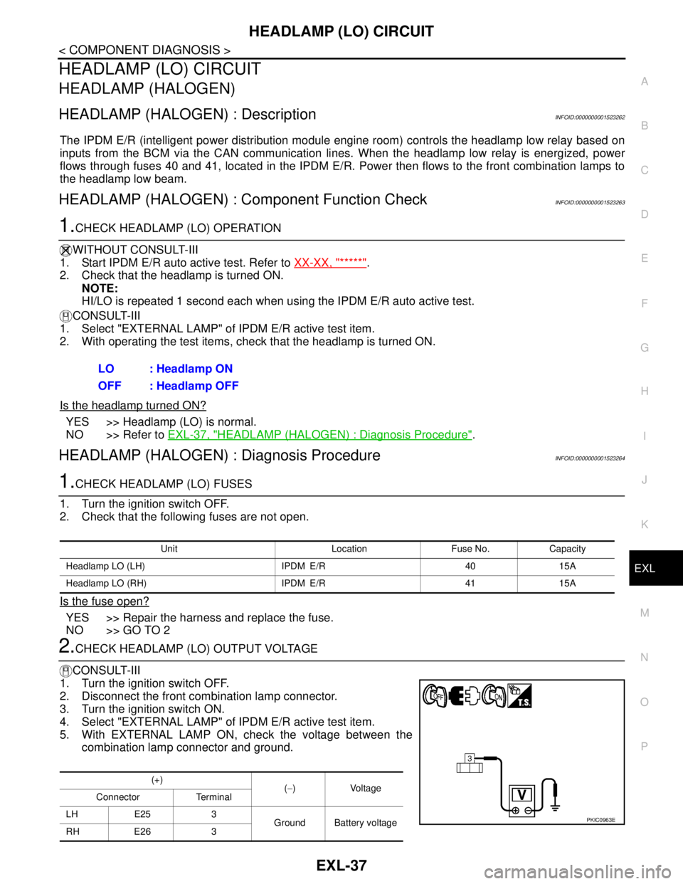
2.CHECK HEADLAMP (LO) OUTPUT VOLTAGE
CONSULT-III
1. Turn the ignition switch OFF.
2. Disconnect the front combination lamp connector.
3. Turn the ignition switch ON.
4. Select "EXTERNAL LAMP" of IPDM E/R active test item.
5. With EXTERNAL LAMP ON, check the voltage between the
combination lamp connector and ground.LO : Headlamp ON
OFF : Headlamp OFF
Unit Location Fuse No. Capacity
Headlamp LO (LH) IPDM E/R 40 15A
Headlamp LO (RH) IPDM E/R 41 15A
(+)
(−)Voltage
Connector Terminal
LH E25 3
Ground Battery voltage
RH E26 3
PKIC0963E
Page 3039 of 5883
EXL-38
< COMPONENT DIAGNOSIS >
HEADLAMP (LO) CIRCUIT
Is the measurement value normal?
YES >> GO TO 4
NO >> GO TO 3
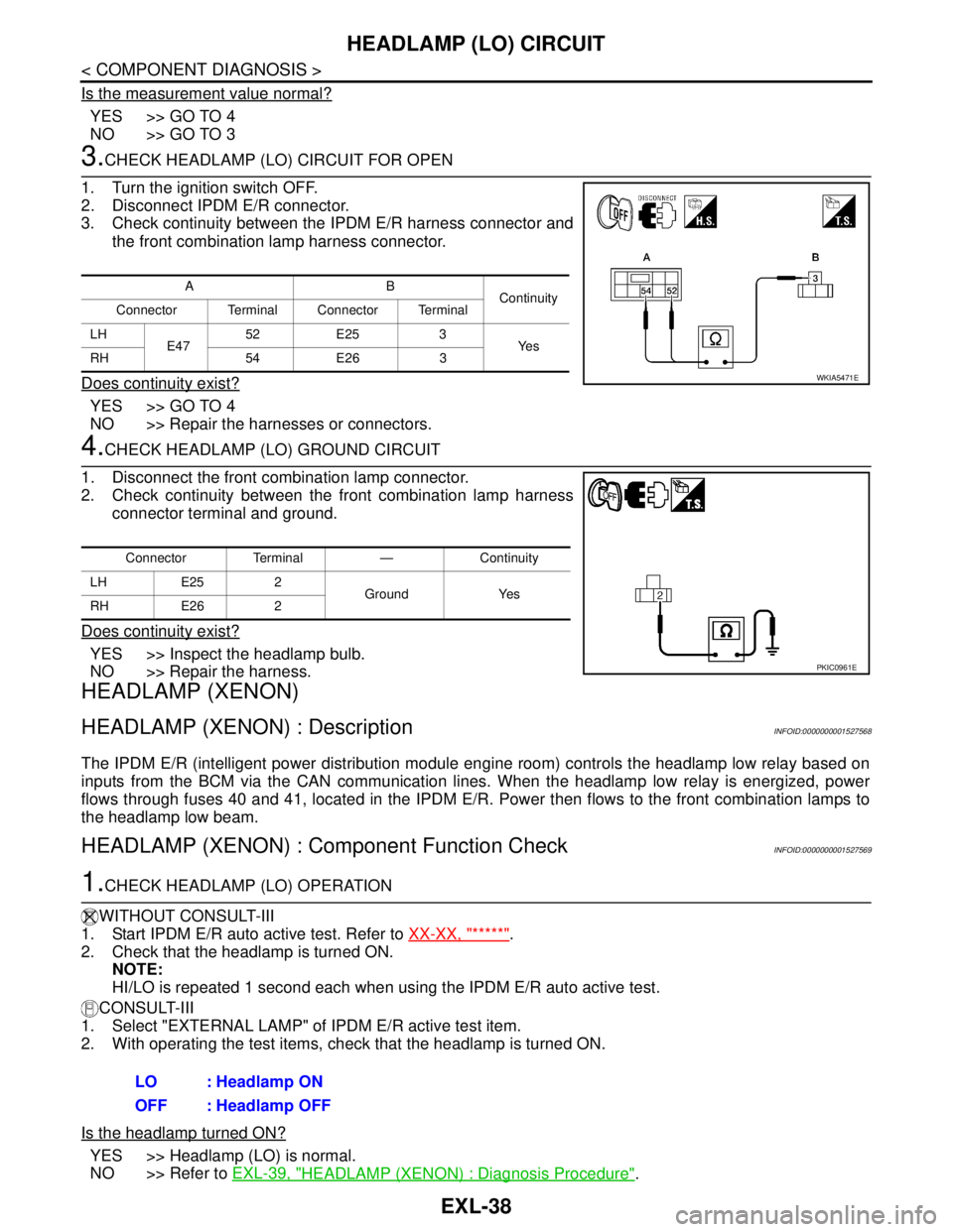
3.CHECK HEADLAMP (LO) CIRCUIT FOR OPEN
1. Turn the ignition switch OFF.
2. Disconnect IPDM E/R connector.
3. Check continuity between the IPDM E/R harness connector and
the front combination lamp harness connector.
Does continuity exist?
YES >> GO TO 4
NO >> Repair the harnesses or connectors.
4.CHECK HEADLAMP (LO) GROUND CIRCUIT
1. Disconnect the front combination lamp connector.
2. Check continuity between the front combination lamp harness
connector terminal and ground.
Does continuity exist?
YES >> Inspect the headlamp bulb.
NO >> Repair the harness.
HEADLAMP (XENON)
HEADLAMP (XENON) : DescriptionINFOID:0000000001527568
The IPDM E/R (intelligent power distribution module engine room) controls the headlamp low relay based on
inputs from the BCM via the CAN communication lines. When the headlamp low relay is energized, power
flows through fuses 40 and 41, located in the IPDM E/R. Power then flows to the front combination lamps to
the headlamp low beam.
HEADLAMP (XENON) : Component Function CheckINFOID:0000000001527569
1.CHECK HEADLAMP (LO) OPERATION
WITHOUT CONSULT-III
1. Start IPDM E/R auto active test. Refer to XX-XX, "*****"
.
2. Check that the headlamp is turned ON.
NOTE:
HI/LO is repeated 1 second each when using the IPDM E/R auto active test.
CONSULT-III
1. Select "EXTERNAL LAMP" of IPDM E/R active test item.
2. With operating the test items, check that the headlamp is turned ON.
Is the headlamp turned ON?
YES >> Headlamp (LO) is normal.
NO >> Refer to EXL-39, "
HEADLAMP (XENON) : Diagnosis Procedure".
AB
Continuity
Connector Terminal Connector Terminal
LH
E4752 E25 3
Ye s
RH 54 E26 3
WKIA5471E
Connector Terminal — Continuity
LH E25 2
Ground Yes
RH E26 2
PKIC0961E
LO : Headlamp ON
OFF : Headlamp OFF
Page 3042 of 5883
FRONT FOG LAMP CIRCUIT
EXL-41
< COMPONENT DIAGNOSIS >
C
D
E
F
G
H
I
J
K
MA
B
EXL
N
O
P
FRONT FOG LAMP CIRCUIT
DescriptionINFOID:0000000001523265
The IPDM E/R (intelligent power distribution module engine room) controls the front fog lamp relay based on
inputs from the BCM via the CAN communication lines. When the front fog lamp relay is energized, power
flows from the front fog lamp relay to fuse 56 in the IPDM E/R and on to the front fog lamps.
Component Function CheckINFOID:0000000001523266
1.CHECK FRONT FOG LAMP OPERATION
CONSULT-III
1. Select "FR FOG LAMP" of IPDM E/R EXTERNAL LAMPS active test item.
2. With test items operating, check that the front fog lamps are turned ON.
Is the front fog lamp turned ON?
YES >> Front fog lamp circuit is normal.
NO >> Refer to EXL-41, "
Diagnosis Procedure".
Diagnosis ProcedureINFOID:0000000001523267
1.CHECK FRONT FOG LAMP FUSE
1. Turn the ignition switch OFF.
2. Check that the following fuses are not open.
Is the fuse open?
YES >> Repair the harness and replace the fuse.
NO >> GO TO 2
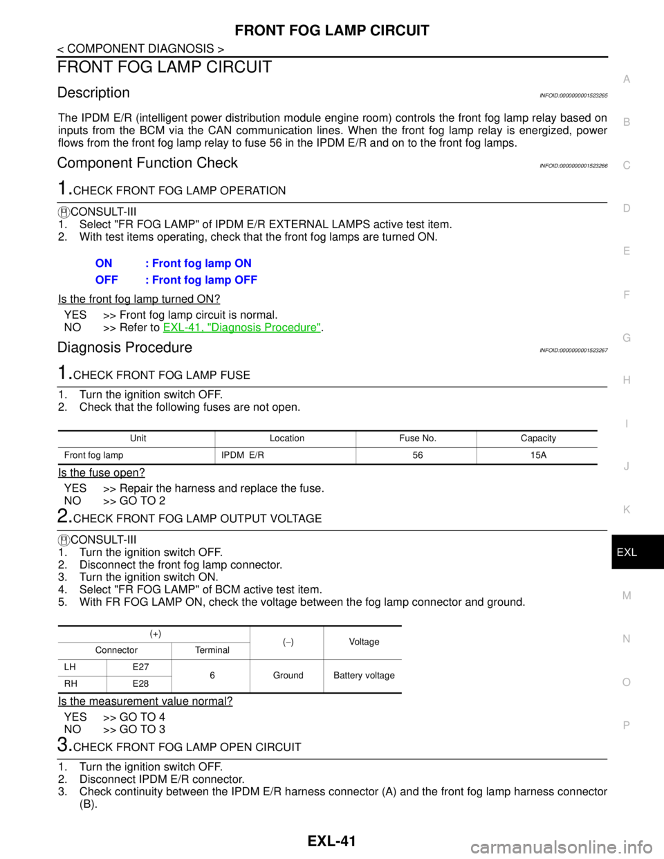
2.CHECK FRONT FOG LAMP OUTPUT VOLTAGE
CONSULT-III
1. Turn the ignition switch OFF.
2. Disconnect the front fog lamp connector.
3. Turn the ignition switch ON.
4. Select "FR FOG LAMP" of BCM active test item.
5. With FR FOG LAMP ON, check the voltage between the fog lamp connector and ground.
Is the measurement value normal?
YES >> GO TO 4
NO >> GO TO 3
3.CHECK FRONT FOG LAMP OPEN CIRCUIT
1. Turn the ignition switch OFF.
2. Disconnect IPDM E/R connector.
3. Check continuity between the IPDM E/R harness connector (A) and the front fog lamp harness connector
(B).ON : Front fog lamp ON
OFF : Front fog lamp OFF
Unit Location Fuse No. Capacity
Front fog lamp IPDM E/R 56 15A
(+)
(−)Voltage
Connector Terminal
LH E27
6 Ground Battery voltage
RH E28
Page 3047 of 5883
EXL-46
< COMPONENT DIAGNOSIS >
PARKING LAMP CIRCUIT
PARKING LAMP CIRCUIT
WITH DAYTIME LIGHT SYSTEM
WITH DAYTIME LIGHT SYSTEM : DescriptionINFOID:0000000001523268
The IPDM E/R (Intelligent Power Distribution Module Engine Room) controls the daytime light relay based on
inputs from the BCM via the CAN communication lines. When the daytime light relay is energized power flows
to the front and rear combination lamps and the license plate lamps.
WITH DAYTIME LIGHT SYSTEM : Component Function CheckINFOID:0000000001523269
1.CHECK PARKING LAMP OPERATION
CONSULT-III
1. Select "TAIL LAMP" of IPDM E/R active test item.
2. With test items operating, check that the parking lamps are turned ON.
Is the parking lamp turned ON?
YES >> Parking lamp circuit is normal.
NO >> Refer to EXL-46, "
WITH DAYTIME LIGHT SYSTEM : Diagnosis Procedure".
WITH DAYTIME LIGHT SYSTEM : Diagnosis ProcedureINFOID:0000000001523270
1.CHECK PARKING LAMP FUSE
1. Turn the ignition switch OFF.
2. Check that the following fuse is not open.
Is the fuse open?
YES >> Repair the harness and replace the fuse.
NO >> GO TO 2
2.CHECK DAYTIME LIGHT RELAY OUTPUT (VOLTAGE)
CONSULT-III
1. Turn the ignition switch OFF.
2. Disconnect the front or rear combination lamp connectors.
3. Turn the ignition switch ON.
4. Select "TAIL LAMP" of IPDM E/R active test item.
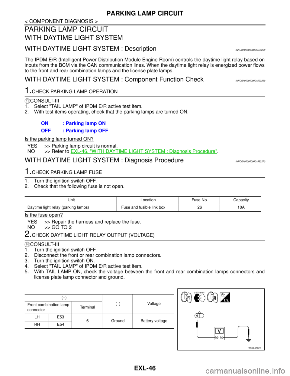
5. With TAIL LAMP ON, check the voltage between the front and rear combination lamps connectors and
license plate lamp connector and ground.ON : Parking lamp ON
OFF : Parking lamp OFF
Unit Location Fuse No. Capacity
Daytime light relay (parking lamps) Fuse and fusible link box 26 10A
(+)
(−)Voltage
Front combination lamp
connectorTe r m i n a l
LH E53
6 Ground Battery voltage
RH E54
WKIA5502E
Page 3049 of 5883
EXL-48
< COMPONENT DIAGNOSIS >
PARKING LAMP CIRCUIT
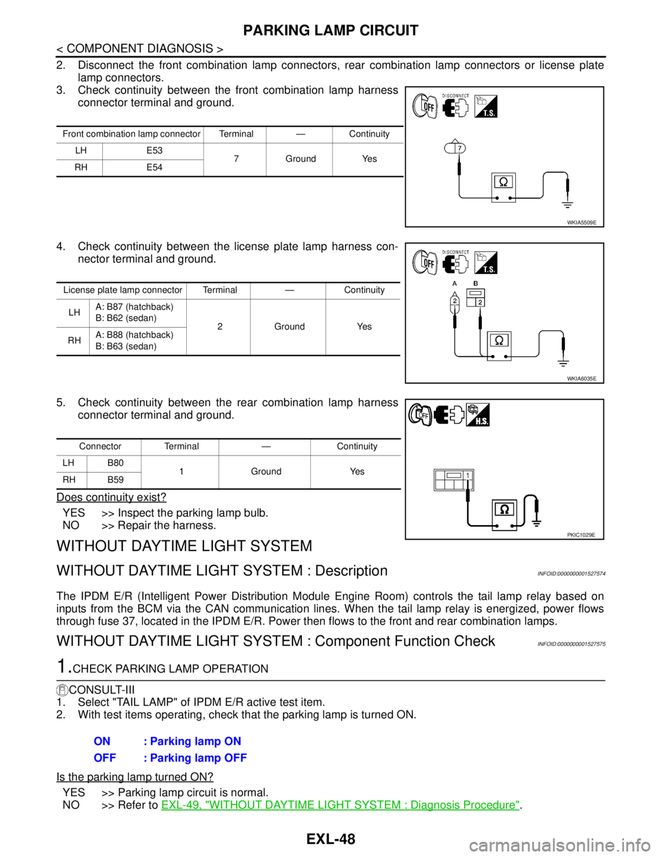
2. Disconnect the front combination lamp connectors, rear combination lamp connectors or license plate
lamp connectors.
3. Check continuity between the front combination lamp harness
connector terminal and ground.
4. Check continuity between the license plate lamp harness con-
nector terminal and ground.
5. Check continuity between the rear combination lamp harness
connector terminal and ground.
Does continuity exist?
YES >> Inspect the parking lamp bulb.
NO >> Repair the harness.
WITHOUT DAYTIME LIGHT SYSTEM
WITHOUT DAYTIME LIGHT SYSTEM : DescriptionINFOID:0000000001527574
The IPDM E/R (Intelligent Power Distribution Module Engine Room) controls the tail lamp relay based on
inputs from the BCM via the CAN communication lines. When the tail lamp relay is energized, power flows
through fuse 37, located in the IPDM E/R. Power then flows to the front and rear combination lamps.
WITHOUT DAYTIME LIGHT SYSTEM : Component Function CheckINFOID:0000000001527575
1.CHECK PARKING LAMP OPERATION
CONSULT-III
1. Select "TAIL LAMP" of IPDM E/R active test item.
2. With test items operating, check that the parking lamp is turned ON.
Is the parking lamp turned ON?
YES >> Parking lamp circuit is normal.
NO >> Refer to EXL-49, "
WITHOUT DAYTIME LIGHT SYSTEM : Diagnosis Procedure".
Front combination lamp connector Terminal — Continuity
LH E53
7GroundYes
RH E54
WKIA5509E
License plate lamp connector Terminal — Continuity
LHA: B87 (hatchback)
B: B62 (sedan)
2GroundYes
RHA: B88 (hatchback)
B: B63 (sedan)
WKIA6035E
Connector Terminal — Continuity
LH B80
1Ground Yes
RH B59
PKIC1029E
ON : Parking lamp ON
OFF : Parking lamp OFF
Page 3195 of 5883

GI-1
GENERAL INFORMATION
C
D
E
F
G
H
I
J
K
L
MB
GI
SECTION GI
N
O
P
CONTENTS
GENERAL INFORMATION
HOW TO USE THIS MANUAL ......................3
HOW TO USE THIS MANUAL ............................3
Description ................................................................3
Terms ........................................................................3
Units ..........................................................................3
Contents ....................................................................3
Relation between Illustrations and Descriptions .......4
Component ................................................................4
How to Follow Trouble Diagnosis ..............................5
How to Read Wiring Diagram ....................................9
Abbreviations ..........................................................16
HOW TO FOLLOW TROUBLE DIAGNOSES ....18
Description ..............................................................18
How to Follow Test Groups in Trouble Diagnosis ....18
Key to Symbols Signifying Measurements or Pro-
cedures ...................................................................
19
HOW TO READ WIRING DIAGRAMS ...............21
Connector symbols .................................................21
Sample/wiring diagram -example- ...........................22
Description ..............................................................23
ABBREVIATIONS ..............................................25
Abbreviation List ......................................................25
TIGHTENING TORQUE OF STANDARD
BOLTS ................................................................
26
Tightening Torque Table .........................................26
RECOMMENDED CHEMICAL PRODUCTS
AND SEALANTS ................................................
27
Recommended Chemical Products and Sealants ....27
TERMINOLOGY .................................................28
SAE J1930 Terminology List ...................................28
FEATURES OF NEW MODEL .....................32
IDENTIFICATION INFORMATION .....................32
Model Variation .......................................................32
Dimensions ..............................................................41
Wheels & Tires ........................................................42
PRECAUTION ..............................................43
PRECAUTIONS .................................................43
Description ...............................................................43
Precaution for Supplemental Restraint System
(SRS) "AIR BAG" and "SEAT BELT PRE-TEN-
SIONER" .................................................................
43
Precaution Necessary for Steering Wheel Rota-
tion After Battery Disconnect ...................................
43
General Precaution ..................................................44
Precaution for Three Way Catalyst ..........................45
Precaution for Fuel (Unleaded Regular Gasoline
Recommended) .......................................................
45
Precaution for Multiport Fuel Injection System or
Engine Control System ............................................
46
Precaution for Hoses ...............................................46
Precaution for Engine Oils .......................................47
Precaution for Air Conditioning ................................47
LIFTING POINT .................................................48
Special Service Tool ................................................48
Garage Jack and Safety Stand and 2-Pole Lift .......48
Board-On Lift ...........................................................49
TOW TRUCK TOWING .....................................50
Tow Truck Towing ...................................................50
Vehicle Recovery (Freeing a Stuck Vehicle) ...........50
BASIC INSPECTION ...................................51
SERVICE INFORMATION FOR ELECTRICAL
INCIDENT ..........................................................
51
Work Flow ................................................................51
Control Units and Electrical Parts ............................51
How to Check Terminal ...........................................52
Intermittent Incident .................................................55
Circuit Inspection .....................................................58
CONSULT-III CHECKING SYSTEM .................63
Page 3222 of 5883

GI-28
< HOW TO USE THIS MANUAL >
TERMINOLOGY
TERMINOLOGY
SAE J1930 Terminology ListINFOID:0000000001691466
All emission related terms used in this publication in accordance with SAE J1930 are listed. Accordingly, new
terms, new acronyms/abbreviations and old terms are listed in the following chart.
NEW TERMNEW ACRONYM /
ABBREVIATIONOLD TERM
Air cleaner ACL Air cleaner
Barometric pressure BARO ***
Barometric pressure sensor-BCDD BAROS-BCDD BCDD
Camshaft position CMP ***
Camshaft position sensor CMPS Crank angle sensor
Canister *** Canister
Carburetor CARB Carburetor
Charge air cooler CAC Intercooler
Closed loop CL Closed loop
Closed throttle position switch CTP switch Idle switch
Clutch pedal position switch CPP switch Clutch switch
Continuous fuel injection system CFI system ***
Continuous trap oxidizer system CTOX system ***
Crankshaft position CKP ***
Crankshaft position sensor CKPS ***
Data link connector DLC ***
Data link connector for CONSULT-III DLC for CONSULT-III Diagnostic connector for CONSULT-III
Diagnostic test mode DTM Diagnostic mode
Diagnostic test mode selector DTM selector Diagnostic mode selector
Diagnostic test mode I DTM I Mode I
Diagnostic test mode II DTM II Mode II
Diagnostic trouble code DTC Malfunction code
Direct fuel injection system DFI system ***
Distributor ignition system DI system Ignition timing control
Early fuel evaporation-mixture heater EFE-mixture heater Mixture heater
Early fuel evaporation system EFE system Mixture heater control
Electrically erasable programmable read
only memoryEEPROM ***
Electronic ignition system EI system Ignition timing control
Engine control EC ***
Engine control module ECM ECCS control unit
Engine coolant temperature ECT Engine temperature
Engine coolant temperature sensor ECTS Engine temperature sensor
Engine modification EM ***
Engine speed RPM Engine speed
Erasable programmable read only memory EPROM ***
Evaporative emission canister EVAP canister Canister
Evaporative emission system EVAP system Canister control solenoid valve
Exhaust gas recirculation valve EGR valve EGR valve