2007 NISSAN TIIDA fuel cap
[x] Cancel search: fuel capPage 2936 of 5883
![NISSAN TIIDA 2007 Service Repair Manual ROCKER COVER
EM-289
< ON-VEHICLE REPAIR >[K9K]
C
D
E
F
G
H
I
J
K
L
MA
EM
N
P O
ROCKER COVER
Exploded ViewINFOID:0000000001381497
Removal and InstallationINFOID:0000000001381498
REMOVAL
1. Remove engin](/manual-img/5/57395/w960_57395-2935.png "NISSAN TIIDA 2007 Service Repair Manual ROCKER COVER
EM-289
< ON-VEHICLE REPAIR >[K9K]
C
D
E
F
G
H
I
J
K
L
MA
EM
N
P O
ROCKER COVER
Exploded ViewINFOID:0000000001381497
Removal and InstallationINFOID:0000000001381498
REMOVAL
1. Remove engin")
ROCKER COVER
EM-289
< ON-VEHICLE REPAIR >[K9K]
C
D
E
F
G
H
I
J
K
L
MA
EM
N
P O
ROCKER COVER
Exploded ViewINFOID:0000000001381497
Removal and InstallationINFOID:0000000001381498
REMOVAL
1. Remove engine cover.
2. Remove air duct (inlet). Refer to EM-269, "
Exploded View".
3. Remove air duct (suction). Refer to EM-269, "
Exploded View".
4. Remove charge air cooler pipes and hoses. Refer to EM-270, "
Exploded View".
5. Disconnect and remove camshaft position sensor.
6. Remove fuel hose shield.
7. Disconnect electronic throttle control actuator. Refer to EM-272, "
Exploded View".
8. Remove blow-by hose.
9. Remove high pressure pipes protection cover (upper).
10. Unclip fuel injector spill hose from rocker cover.
11. Unclip timing belt upper cover.
12. Remove rocker cover.
NOTE:
Loosen bolts in the reverse order as shown.
INSTALLATION
1. Install new gasket to rocker cover.
1. Oil filler cap 2. Rocker cover 3. Gasket
4. Camshaft position sensor
E1BIA0006GB
E1BIA0048ZZ
Page 3164 of 5883
FL-4
< ON-VEHICLE MAINTENANCE >
FUEL SYSTEM
ON-VEHICLE MAINTENANCE
FUEL SYSTEM
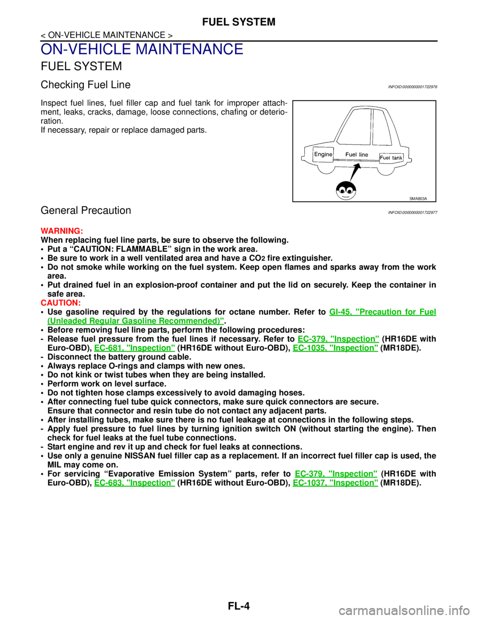
Checking Fuel LineINFOID:0000000001722976
Inspect fuel lines, fuel filler cap and fuel tank for improper attach-
ment, leaks, cracks, damage, loose connections, chafing or deterio-
ration.
If necessary, repair or replace damaged parts.
General PrecautionINFOID:0000000001722977
WARNING:
When replacing fuel line parts, be sure to observe the following.
Put a “CAUTION: FLAMMABLE” sign in the work area.
Be sure to work in a well ventilated area and have a CO
2 fire extinguisher.
Do not smoke while working on the fuel system. Keep open flames and sparks away from the work
area.
Put drained fuel in an explosion-proof container and put the lid on securely. Keep the container in
safe area.
CAUTION:
Use gasoline required by the regulations for octane number. Refer to GI-45, "
Precaution for Fuel
(Unleaded Regular Gasoline Recommended)".
Before removing fuel line parts, perform the following procedures:
- Release fuel pressure from the fuel lines if necessary. Refer to EC-379, "
Inspection" (HR16DE with
Euro-OBD), EC-681, "
Inspection" (HR16DE without Euro-OBD), EC-1035, "Inspection" (MR18DE).
- Disconnect the battery ground cable.
Always replace O-rings and clamps with new ones.
Do not kink or twist tubes when they are being installed.
Perform work on level surface.
Do not tighten hose clamps excessively to avoid damaging hoses.
After connecting fuel tube quick connectors, make sure quick connectors are secure.
Ensure that connector and resin tube do not contact any adjacent parts.
After installing tubes, make sure there is no fuel leakage at connections in the following steps.
- Apply fuel pressure to fuel lines by turning ignition switch ON (without starting the engine). Then
check for fuel leaks at the fuel tube connections.
- Start engine and rev it up and check for fuel leaks at connections.
Use only a genuine NISSAN fuel filler cap as a replacement. If an incorrect fuel filler cap is used, the
MIL may come on.
For servicing “Evaporative Emission System” parts, refer to EC-379, "
Inspection" (HR16DE with
Euro-OBD), EC-683, "
Inspection" (HR16DE without Euro-OBD), EC-1037, "Inspection" (MR18DE).
SMA803A
Page 3166 of 5883
FL-6
< ON-VEHICLE REPAIR >
FUEL LEVEL SENSOR UNIT, FUEL FILTER AND FUEL PUMP ASSEMBLY
b. Disconnect fuel filler hose from fuel filler tube. Refer to FL-10, "HR16DE, HR18DE".
c. Insert fuel tubing into fuel tank through fuel filler hose to drain fuel from fuel tank.
2. Release the fuel pressure from the fuel lines. Refer to EC-377, "
Inspection" (HR16DE with EURO-OBD),
EC-681, "
Inspection" (HR16DE without EURO-OBD), EC-1035, "Inspection" (MR18DE).
3. Open fuel filler lid.
4. Open fuel door and unscrew the fuel filler cap to release the pressure inside the fuel tank.
5. Remove rear seat bottom. Refer to SE-18, "
Removal and Installation".
6. Turn the four retainers 90° in a clockwise direction and remove the fuel pump inspection hole cover.
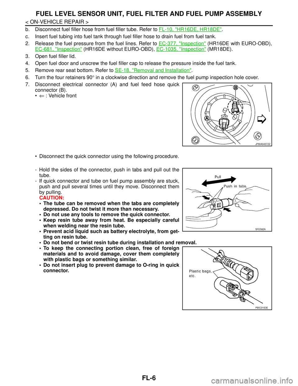
7. Disconnect electrical connector (A) and fuel feed hose quick
connector (B).
⇐ : Vehicle front
Disconnect the quick connector using the following procedure.
- Hold the sides of the connector, push in tabs and pull out the
tube.
- If quick connector and tube on fuel pump assembly are stuck,
push and pull several times until they move. Disconnect them
by pulling.
CAUTION:
The tube can be removed when the tabs are completely
depressed. Do not twist it more than necessary.
Do not use any tools to remove the quick connector.
Keep resin tube away from heat. Be especially careful
when welding near the resin tube.
Prevent acid liquid such as battery electrolyte, from get-
ting on resin tube.
Do not bend or twist resin tube during installation and removal.
To keep the connecting portion clean, free of foreign
materials and to avoid damage, cover them completely
with plastic bags or something similar.
Do not insert plug to prevent damage to O-ring in quick
connector.
JPBIA0457ZZ
SFE562A
PBIC0163E
Page 3169 of 5883
FUEL LEVEL SENSOR UNIT, FUEL FILTER AND FUEL PUMP ASSEMBLY
FL-9
< ON-VEHICLE REPAIR >
C
D
E
F
G
H
I
J
K
L
MA
FL
N
P O
1. Disconnect battery ground cable.
2. Open fuel filler lid and filler cap to release the pressure inside the fuel tank.
3. Remove rear seat cushion. Refer to SE-18, "
Removal and Installation".
4. Remove the fuel pump inspection hole cover.
5. Disconnect electrical connector.
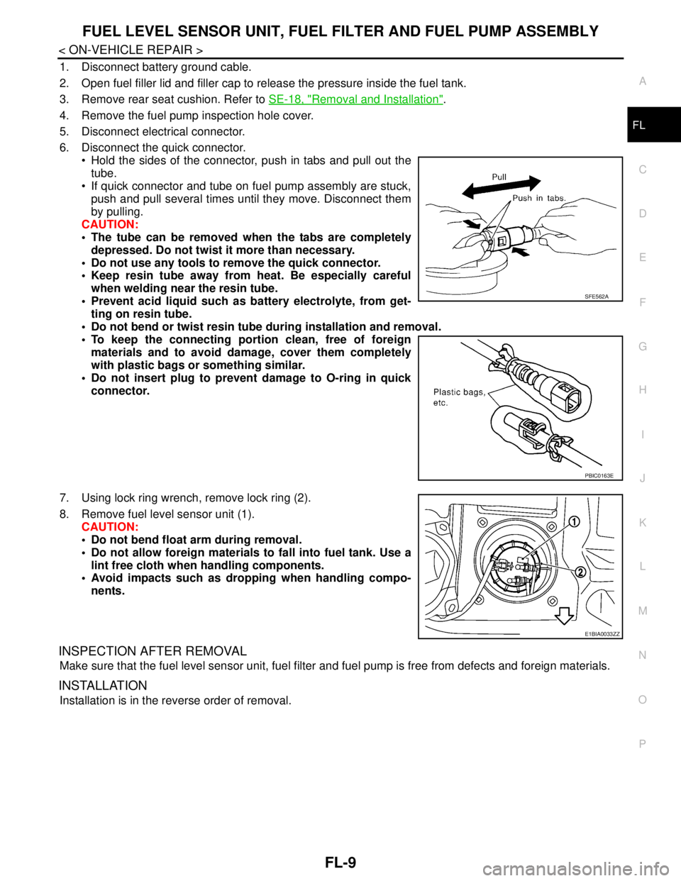
6. Disconnect the quick connector.
Hold the sides of the connector, push in tabs and pull out the
tube.
If quick connector and tube on fuel pump assembly are stuck,
push and pull several times until they move. Disconnect them
by pulling.
CAUTION:
The tube can be removed when the tabs are completely
depressed. Do not twist it more than necessary.
Do not use any tools to remove the quick connector.
Keep resin tube away from heat. Be especially careful
when welding near the resin tube.
Prevent acid liquid such as battery electrolyte, from get-
ting on resin tube.
Do not bend or twist resin tube during installation and removal.
To keep the connecting portion clean, free of foreign
materials and to avoid damage, cover them completely
with plastic bags or something similar.
Do not insert plug to prevent damage to O-ring in quick
connector.
7. Using lock ring wrench, remove lock ring (2).
8. Remove fuel level sensor unit (1).
CAUTION:
Do not bend float arm during removal.
Do not allow foreign materials to fall into fuel tank. Use a
lint free cloth when handling components.
Avoid impacts such as dropping when handling compo-
nents.
INSPECTION AFTER REMOVAL
Make sure that the fuel level sensor unit, fuel filter and fuel pump is free from defects and foreign materials.
INSTALLATION
Installation is in the reverse order of removal.
SFE562A
PBIC0163E
E1BIA0033ZZ
Page 3170 of 5883
FL-10
< ON-VEHICLE REPAIR >
FUEL TANK
FUEL TANK
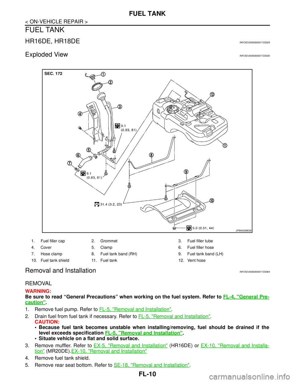
HR16DE, HR18DEINFOID:0000000001723029
Exploded ViewINFOID:0000000001723030
Removal and InstallationINFOID:0000000001723064
REMOVAL
WARNING:
Be sure to read “General Precautions” when working on the fuel system. Refer to FL-4, "
General Pre-
caution".
1. Remove fuel pump. Refer to FL-5, "
Removal and Installation".
2. Drain fuel from fuel tank if necessary. Refer to FL-5, "
Removal and Installation".
CAUTION:
Because fuel tank becomes unstable when installing/removing, fuel should be drained if the
level exceeds specification FL-5, "
Removal and Installation".
Situate vehicle on a flat and solid surface.
3. Remove muffler. Refer to EX-5, "
Removal and Installation" (HR16DE) or EX-10, "Removal and Installa-
tion" (MR20DE).EX-10, "Removal and Installation"
4. Remove fuel tank shield.
5. Remove rear seat bottom. Refer to SE-18, "
Removal and Installation".
1. Fuel filler cap 2. Grommet 3. Fuel filler tube
4. Cover 5. Clamp 6. Fuel filler hose
7. Hose clamp 8. Fuel tank band (RH) 9. Fuel tank band (LH)
10. Fuel tank shield 11. Fuel tank 12. Vent hose
JPBIA0298GB
Page 3173 of 5883
FUEL TANK
FL-13
< ON-VEHICLE REPAIR >
C
D
E
F
G
H
I
J
K
L
MA
FL
N
P O
K9KINFOID:0000000001723031
Exploded ViewINFOID:0000000001723037
Removal and InstallationINFOID:0000000001722981
REMOVAL
WARNING:
Be sure to read “General Precautions” when working on the fuel system. Refer to FL-4, "
General Pre-
caution".
1. Remove RH rear wheel.
2. Remove fuel level sensor unit. Refer to FL-8, "
Removal and Installation".
CAUTION:
If fuel tank bottom face is not level, and remaining fuel level is high, tank position becomes
unstable, causing a danger. Drain fuel further than that in step 1 of the referenced procedure
until tank can be held by hand even if the balance is lost..
3. Remove muffler. Refer to EX-14, "
Removal and Installation"
4. Remove vehicle side insulator on upper center muffler and main muffler..
5. Move parking brake cable from the lower face of fuel tank. Then remove clips for parking brake cable. .
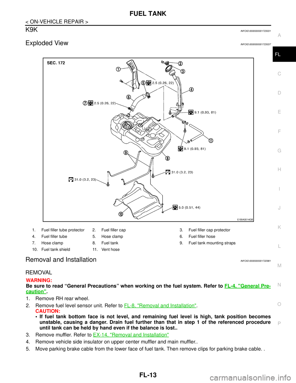
1. Fuel filler tube protector 2. Fuel filler cap 3. Fuel filler cap protector
4. Fuel filler tube 5. Hose clamp 6. Fuel filler hose
7. Hose clamp 8. Fuel tank 9. Fuel tank mounting straps
10. Fuel tank shield 11. Vent hose
E1BIA0014GB
Page 3176 of 5883
FL-16
< SERVICE DATA AND SPECIFICATIONS (SDS)
SERVICE DATA AND SPECIFICATIONS (SDS)
SERVICE DATA AND SPECIFICATIONS (SDS)
SERVICE DATA AND SPECIFICATIONS (SDS)
Standard and LimitINFOID:0000000001722982
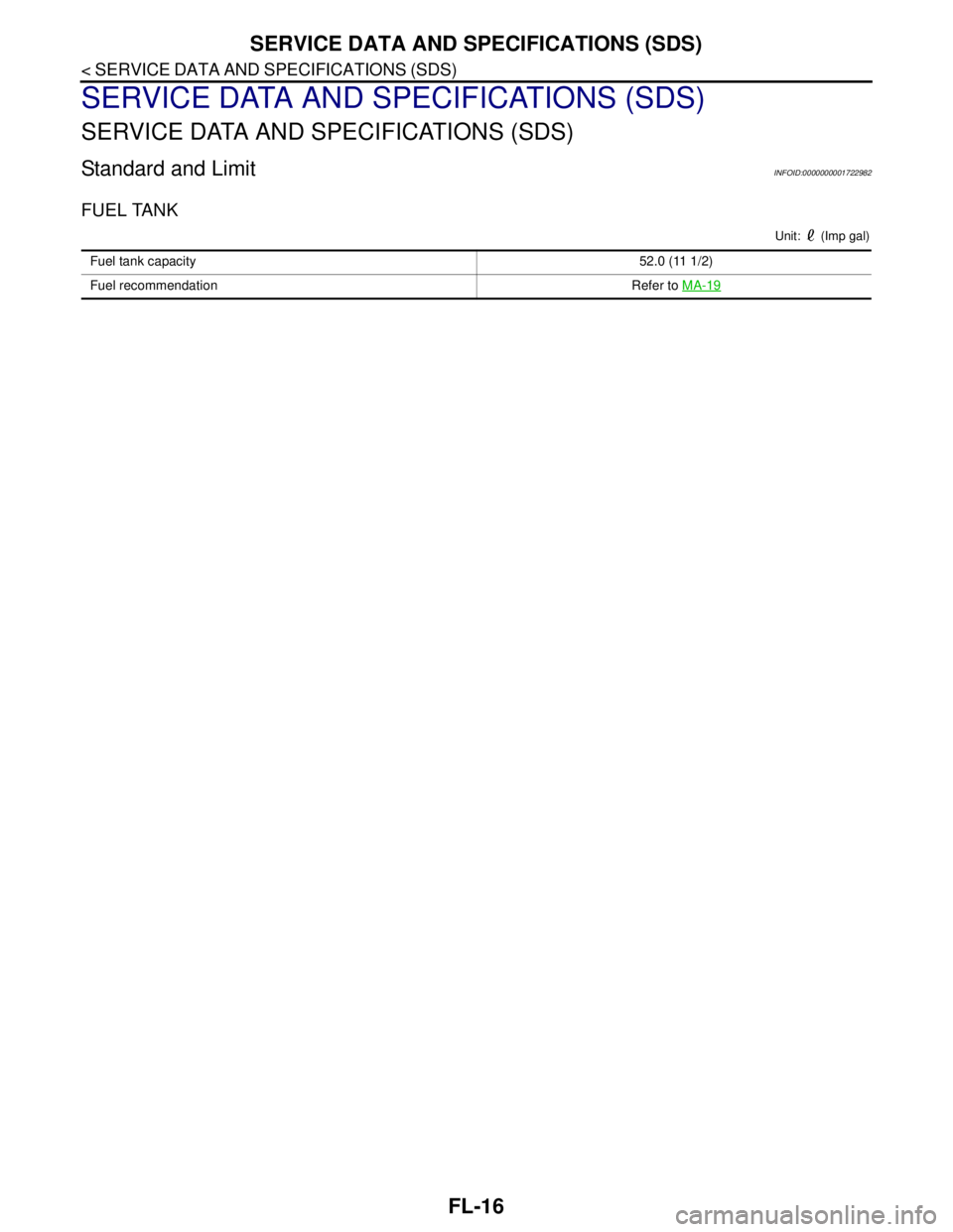
FUEL TANK
Unit: (Imp gal)
Fuel tank capacity52.0 (11 1/2)
Fuel recommendation Refer to MA-19
Page 3182 of 5883
FSU-6
< ON-VEHICLE MAINTENANCE >
FRONT SUSPENSION ASSEMBLY
ON-VEHICLE MAINTENANCE
FRONT SUSPENSION ASSEMBLY
On-Vehicle Inspection and ServiceINFOID:0000000001716890
Make sure the mounting conditions (looseness, back lash) of each component and component conditions
(wear, damage) are normal.
INSPECTION OF LOWER BALL JOINT END PLAY
1. Set front wheels in a straight-ahead position. Do not depress brake pedal.
2. Place an iron bar or similar tool between transverse link and steering knuckle.
3. Measure axial end play by prying it up and down.
CAUTION:
Be careful not to damage ball joint boot. Do not damage the installation position by applying
excessive force.
STRUT INSPECTION
Check for oil leakage, damage and replace as necessary.
Wheel Alignment InspectionINFOID:0000000001716891
PRELIMINARY INSPECTION
WARNING:
Always adjust the alignment with the vehicle on a flat surface.
NOTE:
If alignment is out of specification, inspect and replace any damaged or worn rear suspension parts before
making any adjustments.
1. Check and adjust the wheel alignment with the vehicle under unladen conditions. “Unladen conditions”
means that the fuel, coolant, and lubricant are full; and that the spare tire, jack, hand tools and mats are in
their designated positions.
2. Check the tires for incorrect air pressure and excessive wear.
3. Check the wheels for run out and damage. Refer to WT-5, "
Inspection" .
4. Check the wheel bearing axial end play. Refer to FA X - 5 , "
On-Vehicle Inspection and Service" .
5. Check the shock absorbers for leaks or damage.
6. Check each mounting point of the suspension components for any excessive looseness or damage.
7. Check each link, arm, and the suspension member for any damage.
8. Check the vehicle height. Refer to FSU-18, "
Wheelarch Height (Unladen*)" .
GENERAL INFORMATION AND RECOMMENDATIONS
1. A Four-Wheel Thrust Alignment should be performed.
This type of alignment is recommended for any NISSAN vehicle.
The four-wheel “thrust” process helps ensure that the vehicle is properly aligned and the steering wheel
is centered.
The alignment machine itself should be capable of accepting any NISSAN vehicle.
The alignment machine should be checked to ensure that it is level.
2. Make sure the alignment machine is properly calibrated.
Your alignment machine should be regularly calibrated in order to give correct information.
Check with the manufacturer of your specific alignment machine for their recommended Service/Cali-
bration Schedule.
THE ALIGNMENT PROCESS
IMPORTANT: Use only the alignment specifications listed in this Service Manual. Refer to FSU-17, "Wheel
Alignment (Unladen*)" .
1. When displaying the alignment settings, many alignment machines use “indicators”: (Green/red, plus or
minus, Go/No Go). Do NOT use these indicators. Axial end play : 0 mm (0 in)