2007 NISSAN TIIDA fluids and lubricants
[x] Cancel search: fluids and lubricantsPage 195 of 5883

PRECAUTIONS
BR-3
< PRECAUTION >
C
D
E
G
H
I
J
K
L
MA
B
BR
N
O
P
PRECAUTION
PRECAUTIONS
Precaution for Supplemental Restraint System (SRS) "AIR BAG" and "SEAT BELT
PRE-TENSIONER"
INFOID:0000000001716907
The Supplemental Restraint System such as “AIR BAG” and “SEAT BELT PRE-TENSIONER”, used along
with a front seat belt, helps to reduce the risk or severity of injury to the driver and front passenger for certain
types of collision. This system includes seat belt switch inputs and dual stage front air bag modules. The SRS
system uses the seat belt switches to determine the front air bag deployment, and may only deploy one front
air bag, depending on the severity of a collision and whether the front occupants are belted or unbelted.
Information necessary to service the system safely is included in the SR and SB section of this Service Man-
ual.
WARNING:
• To avoid rendering the SRS inoperative, which could increase the risk of personal injury or death in
the event of a collision which would result in air bag inflation, all maintenance must be performed by
an authorized NISSAN/INFINITI dealer.
Improper maintenance, including incorrect removal and installation of the SRS, can lead to personal
injury caused by unintentional activation of the system. For removal of Spiral Cable and Air Bag
Module, see the SR section.
Do not use electrical test equipment on any circuit related to the SRS unless instructed to in this
Service Manual. SRS wiring harnesses can be identified by yellow and/or orange harnesses or har-
ness connectors.
Precaution for Brake SystemINFOID:0000000001716908
Refill using recommended brake fluid. Refer to MA-19, "Fluids and Lubricants".
Never reuse drained brake fluid.
Be careful not to splash brake fluid on painted surface of body. If brake fluid is splashed on painted surfaces
of body immediately wipe it off with cloth and then wash it away with water.
To clean or wash all parts of master cylinder, disc brake caliper and wheel cylinder, use new brake fluid.
Never use mineral oils such as gasoline or kerosene. They will ruin rubber parts of the hydraulic system.
Use a flare nut wrench when removing a brake tube and use a
flare nut torque wrench when installing a brake tube.
When installing brake tubes and hoses, be sure to check torque.
Before working, turn ignition switch OFF and disconnect connec-
tors of ABS actuator and electric unit (control unit) or the battery
cable from the negative terminal.
Burnish the new braking surfaces after refinishing or replacing
drums or rotors, after replacing pads or linings, or if a soft pedal
occurs at very low mileage. Refer toBR-26, "
Brake Burnishing" .
SBR686C
Page 200 of 5883

BR-8
< ON-VEHICLE MAINTENANCE >
BRAKE FLUID
BRAKE FLUID
On Board InspectionINFOID:0000000001716919
CHECKING BRAKE FLUID LEVEL
Make sure the fluid level in the reservoir tank is within the standard
(between MAX and MIN lines).
Visually check around the reservoir tank for fluid leakage.
If fluid level is excessively low, check brake system for fluid leak-
age.
Release parking brake lever and see if brake warning lamp goes
off. If not, check brake system for fluid leakage.
Drain and RefillINFOID:0000000001716920
CAUTION:
Refill using recommended brake fluid. Refer to MA-19, "
Fluids and Lubricants".
Never reuse drained brake fluid.
Be careful not to splash brake fluid on painted areas; it may cause paint damage. If brake fluid is
splashed on painted areas, immediately wipe them with cloth and wash it away with water.
Before working, disconnect connectors of ABS actuator and electric unit (control unit) or battery
cable from the negative terminal.
1. Connect a vinyl tube to bleed valve.
2. Depress the brake pedal, loosen the bleed valve, and gradually
remove the brake fluid.
3. Clean inside of reservoir tank, and refill with new brake fluid.
4. Loosen bleed valve, depress brake pedal slowly to full stroke
and then release it. Repeat the procedure every 2 or 3 seconds
until the new brake fluid comes out, then close the bleed valve
while depressing the brake pedal. Repeat the same procedure
for each wheel.
5. Bleed air. Refer to BR-8, "
Bleeding Brake System" .
Bleeding Brake SystemINFOID:0000000001716921
CAUTION:
While bleeding, pay attention to master cylinder fluid level.
Before working, disconnect connectors of ABS actuator and electric unit (control unit) or the battery
cable from the negative terminal.
1. Connect a vinyl tube to the rear right bleed valve.
2. Fully depress brake pedal 4 to 5 times.
SFIA3067E
WFIA0512E
WFIA0513E
Page 206 of 5883
BR-14
< ON-VEHICLE REPAIR >
BRAKE TUBE AND HOSE
BRAKE TUBE AND HOSE
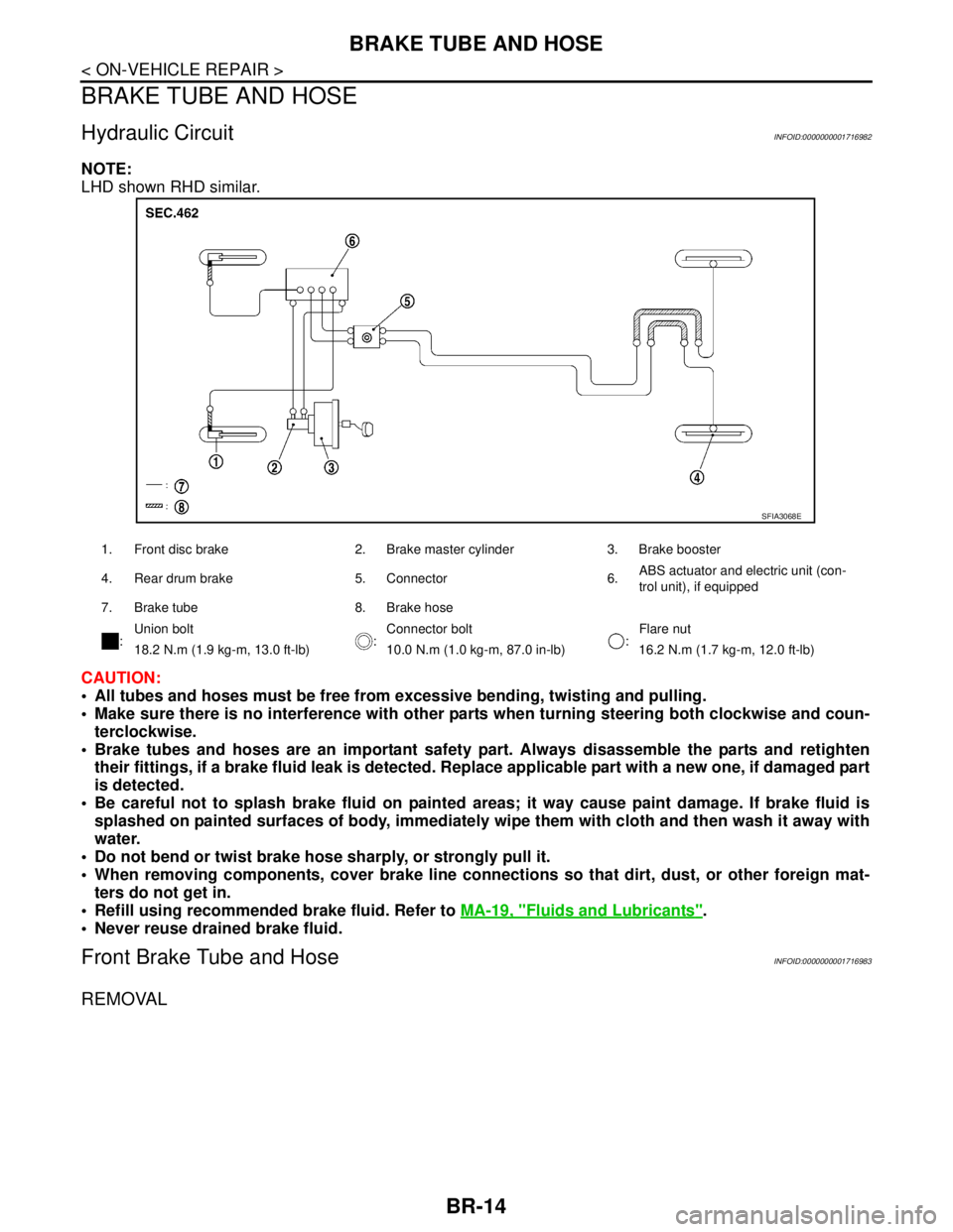
Hydraulic CircuitINFOID:0000000001716982
NOTE:
LHD shown RHD similar.
CAUTION:
All tubes and hoses must be free from excessive bending, twisting and pulling.
Make sure there is no interference with other parts when turning steering both clockwise and coun-
terclockwise.
Brake tubes and hoses are an important safety part. Always disassemble the parts and retighten
their fittings, if a brake fluid leak is detected. Replace applicable part with a new one, if damaged part
is detected.
Be careful not to splash brake fluid on painted areas; it way cause paint damage. If brake fluid is
splashed on painted surfaces of body, immediately wipe them with cloth and then wash it away with
water.
Do not bend or twist brake hose sharply, or strongly pull it.
When removing components, cover brake line connections so that dirt, dust, or other foreign mat-
ters do not get in.
Refill using recommended brake fluid. Refer to MA-19, "
Fluids and Lubricants".
Never reuse drained brake fluid.
Front Brake Tube and HoseINFOID:0000000001716983
REMOVAL
1. Front disc brake 2. Brake master cylinder 3. Brake booster
4. Rear drum brake 5. Connector 6.ABS actuator and electric unit (con-
trol unit), if equipped
7. Brake tube 8. Brake hose
:Union bolt
:Connector bolt
:Flare nut
18.2 N.m (1.9 kg-m, 13.0 ft-lb) 10.0 N.m (1.0 kg-m, 87.0 in-lb) 16.2 N.m (1.7 kg-m, 12.0 ft-lb)
SFIA3068E
Page 209 of 5883

DUAL PROPORTIONING VALVE
BR-17
< ON-VEHICLE REPAIR >
C
D
E
G
H
I
J
K
L
MA
B
BR
N
O
P
DUAL PROPORTIONING VALVE
Removal and InstallationINFOID:0000000001726771
Removal
1. Disconnect brake lines from dual proportioning valve.
Mark brake lines for installation.
2. Remove dual proportioning valve bolt and dual proportioning valve.
3. Remove two bolts and bracket.
Installation
Installation is in the reverse order of removal.
When installing brake lines to the dual proportioning valve, tighten to specifications. Refer to BR-14,
"Hydraulic Circuit".
InspectionINFOID:0000000001726772
CAUTION:
Carefully monitor brake fluid level at master cylinder.
Use the recommended new brake fluid. Refer to MA-19, "
Fluids and Lubricants".
Be careful not to splash brake fluid on painted areas; it may cause paint damage. If brake fluid is
splashed on paint areas, wash it away with water immediately.
1. Connect commercially available brake fluid pressure gauge to
air bleeders of front and rear brakes on either LH and RH side.
2. Bleed air from the Tool.
3. Check fluid pressure by depressing brake pedal.
Unit: kPa (kg/cm2, psi)
If output pressure is out of specification, replace dual proportioning valve.
4. Bleed air after disconnecting the Tool. Refer to BR-8, "
Bleeding Brake System". Applied pressure
(Front brake)7,355 (75, 1,067)
Output pressure
(Rear brake)5,099 - 5,492 (52 - 56, 740 - 796)
SBR822BA
SBR823BA
Page 210 of 5883

BR-18
< ON-VEHICLE REPAIR >
BRAKE MASTER CYLINDER
BRAKE MASTER CYLINDER
On-Board InspectionINFOID:0000000001716996
LEAK INSPECTION
Check for leaking in a master cylinder installation surface, a reservoir tank installation surface, and brake
tube connections.
Removal and InstallationINFOID:0000000001716997
CAUTION:
Be careful not to splash brake fluid on painted areas; it may cause paint damage. If brake fluid is
splashed on painted areas, immediately wipe them with cloth and wash it away with water.
REMOVAL
1. Drain brake fluid. Refer to BR-8, "Drain and Refill" .
2. Remove battery. Refer to PG-6, "
Removal and Installation" .
3. Remove air duct and air cleaner. Refer to EM-27, "
Removal and Installation" (HR16DE), EM-154,
"Removal and Installation" (MR18DE), EM-269, "Removal and Installation" (K9K).
4. Disconnect brake fluid level switch harness connector.
5. Using a flare nut wrench, remove brake tube from master cylinder.
6. Remove master cylinder assembly nuts, and remove master cylinder assembly from vehicle..
INSTALLATION
CAUTION:
Refill using recommended brake fluid. Refer to MA-19, "
Fluids and Lubricants".
Never reuse drained brake fluid.
Check if the rod of primary piston has dust or scratches.
1. Install master cylinder to brake booster assembly, and tighten nuts to the specified torque. Refer to BR-19,
"Removal and Installation".
CAUTION:
Do not damage or strain rod of primary piston.
Apply silicone grease for O-ring, primary piston rod and
to inside of booster.
2. Install brake tube to master cylinder, and temporarily tighten the flare nuts on the brake tube to master cyl-
inder by hand.
3. Install brake tube to brake hose, then tighten flare nut to the specified torque using a flare nut torque
wrench. Refer to BR-14, "
Hydraulic Circuit" .
4. Connect brake fluid level switch harness connector.
5. Refill new brake fluid and bleed air. Refer toBR-8, "
Bleeding Brake System" .
SFIA2614E
Page 220 of 5883

BR-28
< ON-VEHICLE REPAIR >
REAR DISC BRAKE
Removal and Installation of Brake Pad
INFOID:0000000001724667
REMOVAL
1. Remove master cylinder reservoir cap.
2. Remove tires from vehicle with power tool.
3. Remove bottom sliding pin bolt.
4. Hang cylinder body with a wire, and remove pads, pad retainers,
shims from torque member.
INSTALLATION
1. Apply M-77 grease or equivalent between pad plate and shim, shim and shim cover, and shim cover and
piston. Refer to MA-19, "
Fluids and Lubricants".
2. Attach the inner shim and shim cover to the inner pad, and the outer shim and outer shim cover to the
outer pad.
3. Apply M7439 grease or equivalent to pad contact surface of pad retainers.
4. Attach the pad retainers and pads to the torque member.
5. Push the piston in so that the pad is firmly attached and attach the cylinder body to the torque member.
NOTE:
Using a disc brake piston tool (commercial service tool), makes it easier to push in the piston.
CAUTION:
By pushing in the piston, the brake fluid returns to the master cylinder reservoir tank. Watch the
level of the surface of the reservoir tank.
6. Install the sliding pin bolt and tighten to the specification. Refer to BR-27, "
Component".
7. Inspect brake fluid level, then install master cylinder reservoir cap.
8. Check brake for drag.
9. Attach the tires to the vehicle. Refer to WT-6, "
Rotation".
CAUTION:
Burnish the brake contact surfaces when refinishing or replacing brake rotors, after replacing
pads or linings, or if a soft pedal occurs at very low mileage. Refer to BR-29, "
Brake Burnishing".
Removal and Installation of Brake Caliper AssemblyINFOID:0000000001724668
REMOVAL
1. Remove master cylinder reservoir cap.
2. Remove tires from vehicle using power tool.
SBR042C
Page 221 of 5883
REAR DISC BRAKE
BR-29
< ON-VEHICLE REPAIR >
C
D
E
G
H
I
J
K
L
MA
B
BR
N
O
P
3. Drain brake fluid. Refer to BR-8, "Bleeding Brake System".
4. Remove connecting bolt and torque member bolts using power tool, and remove cylinder body.
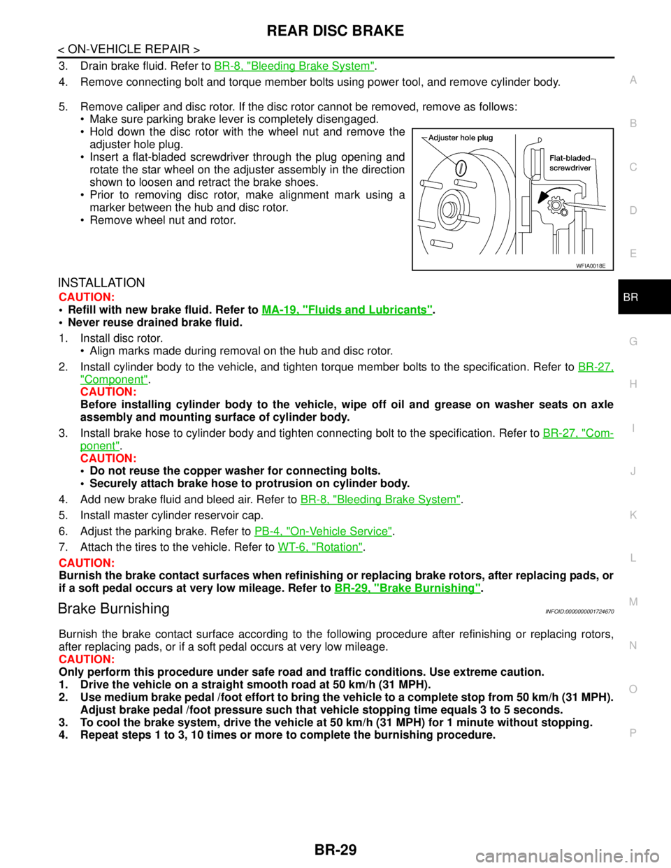
5. Remove caliper and disc rotor. If the disc rotor cannot be removed, remove as follows:
Make sure parking brake lever is completely disengaged.
Hold down the disc rotor with the wheel nut and remove the
adjuster hole plug.
Insert a flat-bladed screwdriver through the plug opening and
rotate the star wheel on the adjuster assembly in the direction
shown to loosen and retract the brake shoes.
Prior to removing disc rotor, make alignment mark using a
marker between the hub and disc rotor.
Remove wheel nut and rotor.
INSTALLATION
CAUTION:
Refill with new brake fluid. Refer to MA-19, "
Fluids and Lubricants".
Never reuse drained brake fluid.
1. Install disc rotor.
Align marks made during removal on the hub and disc rotor.
2. Install cylinder body to the vehicle, and tighten torque member bolts to the specification. Refer to BR-27,
"Component".
CAUTION:
Before installing cylinder body to the vehicle, wipe off oil and grease on washer seats on axle
assembly and mounting surface of cylinder body.
3. Install brake hose to cylinder body and tighten connecting bolt to the specification. Refer to BR-27, "
Com-
ponent".
CAUTION:
Do not reuse the copper washer for connecting bolts.
Securely attach brake hose to protrusion on cylinder body.
4. Add new brake fluid and bleed air. Refer to BR-8, "
Bleeding Brake System".
5. Install master cylinder reservoir cap.
6. Adjust the parking brake. Refer to PB-4, "
On-Vehicle Service".
7. Attach the tires to the vehicle. Refer to WT-6, "
Rotation".
CAUTION:
Burnish the brake contact surfaces when refinishing or replacing brake rotors, after replacing pads, or
if a soft pedal occurs at very low mileage. Refer to BR-29, "
Brake Burnishing".
Brake BurnishingINFOID:0000000001724670
Burnish the brake contact surface according to the following procedure after refinishing or replacing rotors,
after replacing pads, or if a soft pedal occurs at very low mileage.
CAUTION:
Only perform this procedure under safe road and traffic conditions. Use extreme caution.
1. Drive the vehicle on a straight smooth road at 50 km/h (31 MPH).
2. Use medium brake pedal /foot effort to bring the vehicle to a complete stop from 50 km/h (31 MPH).
Adjust brake pedal /foot pressure such that vehicle stopping time equals 3 to 5 seconds.
3. To cool the brake system, drive the vehicle at 50 km/h (31 MPH) for 1 minute without stopping.
4. Repeat steps 1 to 3, 10 times or more to complete the burnishing procedure.
WFIA0018E
Page 467 of 5883

CL-2
< SERVICE INFORMATION >
PRECAUTIONS
SERVICE INFORMATION
PRECAUTIONS
Precaution for Supplemental Restraint System (SRS) "AIR BAG" and "SEAT BELT
PRE-TENSIONER"
INFOID:0000000001375288
The Supplemental Restraint System such as “AIR BAG” and “SEAT BELT PRE-TENSIONER”, used along
with a front seat belt, helps to reduce the risk or severity of injury to the driver and front passenger for certain
types of collision. This system includes seat belt switch inputs and dual stage front air bag modules. The SRS
system uses the seat belt switches to determine the front air bag deployment, and may only deploy one front
air bag, depending on the severity of a collision and whether the front occupants are belted or unbelted.
Information necessary to service the system safely is included in the SRS and SB section of this Service Man-
ual.
WARNING:
• To avoid rendering the SRS inoperative, which could increase the risk of personal injury or death in
the event of a collision which would result in air bag inflation, all maintenance must be performed by
an authorized NISSAN/INFINITI dealer.
Improper maintenance, including incorrect removal and installation of the SRS, can lead to personal
injury caused by unintentional activation of the system. For removal of Spiral Cable and Air Bag
Module, see the SRS section.
Do not use electrical test equipment on any circuit related to the SRS unless instructed to in this
Service Manual. SRS wiring harnesses can be identified by yellow and/or orange harnesses or har-
ness connectors.
Service Notice or PrecautionINFOID:0000000001375289
Use recommended brake fluid when adding fluid to the clutch reservoir tank. Refer to MA-19, "Fluids
and Lubricants".
Do not reuse fluid drained from clutch system.
Do not splash brake fluid on painted areas.
Use new brake fluid to clean or wash all parts of master cylinder and operating cylinder.
Do not use mineral oils such as gasoline or kerosene. It will ruin the rubber parts of the hydraulic
system.
If transaxle assembly is removed from the vehicle, always replace CSC (Concentric slave cylinder).
Return CSC to original position to remove transaxle assembly. Dust on clutch disc sliding parts may
damage CSC seal and may cause clutch fluid leakage.
Do not disassemble clutch master cylinder and CSC.
WARNING:
After cleaning clutch disc, clean it with a dust collector. Do not use compressed air.