2007 NISSAN TIIDA steering wheel adjustment
[x] Cancel search: steering wheel adjustmentPage 4861 of 5883
ST-6
< ON-VEHICLE MAINTENANCE >
STEERING WHEEL
ON-VEHICLE MAINTENANCE
STEERING WHEEL
On-Vehicle Inspection and ServiceINFOID:0000000001282496
CHECKING CONDITION OF INSTALLATION
Check installation conditions of steering gear assembly, front suspension assembly, axle and steering col-
umn assembly.
Check if movement exists when steering wheel is moved up and down, to the left and right and to the axial
direction.
Check steering gear assembly mounting bolts and nuts for looseness. Refer to ST-12, "
Removal and Instal-
lation" .
CHECKING STEERING WHEEL PLAY
Turn steering wheel so that front wheels come to the straight-ahead position. Start engine and lightly turn
steering wheel to the left and right until front wheels start to move. Measure steering wheel movement on the
outer circumference.
When the measurement value is outside the standard value, check backlash for each joint of steering col-
umn assembly and installation condition of steering gear assembly.
CHECKING NEUTRAL POSITION STEERING WHEEL
Make sure that steering gear assembly, steering column assembly and steering wheel are installed in the
correct position.
Perform neutral position inspection after wheel alignment. Refer to SR-2, "
Precaution for Supplemental
Restraint System (SRS) "AIR BAG" and "SEAT BELT PRE-TENSIONER"" .
Set vehicle to the straight-ahead position and confirm steering wheel is in the neutral position.
Loosen outer socket lock nut and turn inner socket to left and right equally to make fine adjustments if steer-
ing wheel is not in the neutral position.
CHECKING STEERING WHEEL TURNING FORCE
1. Park vehicle on a level and dry surface, set parking brake.
2. Start engine.
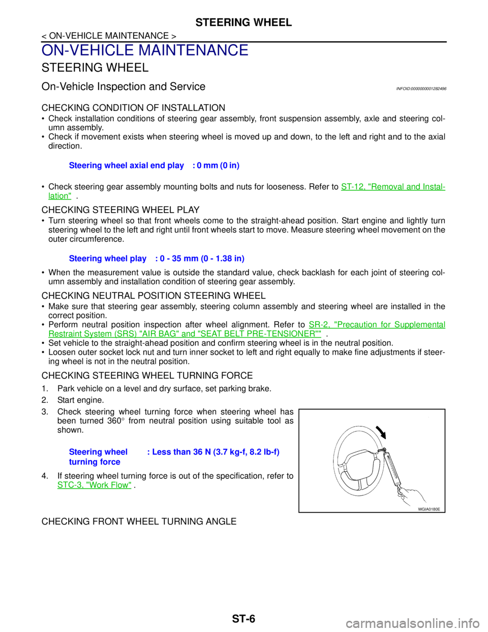
3. Check steering wheel turning force when steering wheel has
been turned 360° from neutral position using suitable tool as
shown.
4. If steering wheel turning force is out of the specification, refer to
STC-3, "
Work Flow" .
CHECKING FRONT WHEEL TURNING ANGLE
Steering wheel axial end play : 0 mm (0 in)
Steering wheel play : 0 - 35 mm (0 - 1.38 in)
Steering wheel
turning force: Less than 36 N (3.7 kg-f, 8.2 lb-f)
WGIA0180E
Page 4872 of 5883
STEERING GEAR
ST-17
< DISASSEMBLY AND ASSEMBLY >
C
D
E
F
H
I
J
K
L
MA
B
ST
N
O
P
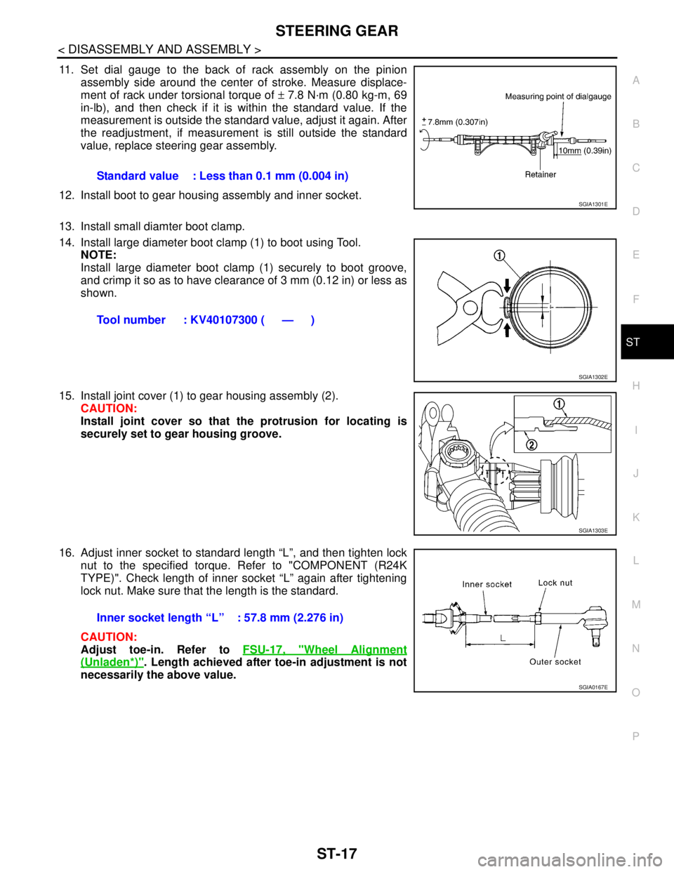
11. Set dial gauge to the back of rack assembly on the pinion
assembly side around the center of stroke. Measure displace-
ment of rack under torsional torque of ± 7.8 N·m (0.80 kg-m, 69
in-lb), and then check if it is within the standard value. If the
measurement is outside the standard value, adjust it again. After
the readjustment, if measurement is still outside the standard
value, replace steering gear assembly.
12. Install boot to gear housing assembly and inner socket.
13. Install small diamter boot clamp.
14. Install large diameter boot clamp (1) to boot using Tool.
NOTE:
Install large diameter boot clamp (1) securely to boot groove,
and crimp it so as to have clearance of 3 mm (0.12 in) or less as
shown.
15. Install joint cover (1) to gear housing assembly (2).
CAUTION:
Install joint cover so that the protrusion for locating is
securely set to gear housing groove.
16. Adjust inner socket to standard length “L”, and then tighten lock
nut to the specified torque. Refer to "COMPONENT (R24K
TYPE)". Check length of inner socket “L” again after tightening
lock nut. Make sure that the length is the standard.
CAUTION:
Adjust toe-in. Refer to FSU-17, "
Wheel Alignment
(Unladen*)". Length achieved after toe-in adjustment is not
necessarily the above value.Standard value : Less than 0.1 mm (0.004 in)
SGIA1301E
Tool number : KV40107300 ( — )
SGIA1302E
SGIA1303E
Inner socket length “L” : 57.8 mm (2.276 in)
SGIA0167E
Page 4890 of 5883
![NISSAN TIIDA 2007 Service Repair Manual STC-16
< COMPONENT DIAGNOSIS >[EPS]
C1608 EPS CONTROL UNIT
C1608 EPS CONTROL UNIT
DescriptionINFOID:0000000001716745
EPS control unit performs an arithmetical operation on data, such as steering wheel](/manual-img/5/57395/w960_57395-4889.png "NISSAN TIIDA 2007 Service Repair Manual STC-16
< COMPONENT DIAGNOSIS >[EPS]
C1608 EPS CONTROL UNIT
C1608 EPS CONTROL UNIT
DescriptionINFOID:0000000001716745
EPS control unit performs an arithmetical operation on data, such as steering wheel")
STC-16
< COMPONENT DIAGNOSIS >[EPS]
C1608 EPS CONTROL UNIT
C1608 EPS CONTROL UNIT
DescriptionINFOID:0000000001716745
EPS control unit performs an arithmetical operation on data, such as steering wheel turning force (sensor sig-
nal) from the torque sensor, vehicle speed signal, etc. Then it generates an optimum assist torque to the EPS
motor according to the driving condition.
DTC LogicINFOID:0000000001716746
DTC DETECTION LOGIC
DTC CONFIRMATION PROCEDURE
1.CHECK SELF-DIAGNOSIS RESULTS
Check the self-diagnosis results.
Is above displayed on the self-diagnosis display?
YES >> Proceed to diagnosis procedure. Refer to STC-16, "Diagnosis Procedure".
NO >> INSPECTION END
Diagnosis ProcedureINFOID:0000000001697728
1.PERFORM SELF-DIAGNOSIS
With CONSULT-III1. Turn ignition switch ON. (Do not start engine.)
2. Select “SELF-DIAG RESULTS” mode for “EPS” with CONSULT-III.
3. Touch “ERASE”.
4. Turn ignition switch OFF, and wait at least 10 seconds.
5. Start engine.
6. Perform the self-diagnosis again.
Is the
“CONTROL UNIT [C1608]” displayed?
YES >> Replace EPS control unit. Refer to ST-9, "Removal and Installation".
NO >>INSPECTION END
Special Repair Requirement (Models with ESP)INFOID:0000000001730967
1.ADJUSTMENT OF STEERING ANGLE SENSOR NEUTRAL POSITION
Always perform the neutral position adjustment for the steering angle sensor, when replacing the EPS control
unit. Refer to BRC-90, "
ADJUSTMENT OF STEERING ANGLE SENSOR NEUTRAL POSITION : Descrip-
tion".
>> END
DTC Display item Malfunction detected condition Possible cause
C1608 CONTROL UNITWhen the internal malfunction is detected in EPS
control unit. Harness or connector
EPS control unit
Self-diagnosis results
CONTROL UNIT
Page 4953 of 5883

TM-7
C
E
F
G
H
I
J
K
L
MA
B
TM
N
O
P Precaution for Supplemental Restraint System
(SRS) "AIR BAG" and "SEAT BELT PRE-TEN-
SIONER" ...............................................................
465
Precaution Necessary for Steering Wheel Rota-
tion After Battery Disconnect .................................
465
Precaution for On Board Diagnosis (OBD) System
of A/T and Engine (For Type1 Only) .....................
465
Precaution .............................................................466
Service Notice or Precaution .................................467
Wiring Diagram and Trouble Diagnosis ................467
PREPARATION .........................................468
PREPARATION ................................................468
Special Service Tool .............................................468
Commercial Service Tool ......................................471
ON-VEHICLE MAINTENANCE ..................473
A/T FLUID .........................................................473
Checking A/T Fluid ................................................473
Changing A/T Fluid ...............................................473
A/T Fluid Cooler Cleaning .....................................474
STALL TEST ....................................................477
Inspection and Judgment ......................................477
LINE PRESSURE TEST ...................................480
Inspection and Judgment ......................................480
ROAD TEST .....................................................482
Description ............................................................482
Check Before Engine Is Started ............................482
Check at Idle .........................................................483
Cruise Test - Part 1 ...............................................485
Cruise Test - Part 2 ...............................................487
Cruise Test - Part 3 ...............................................488
Vehicle Speed When Shifting Gears .....................490
Vehicle Speed When Performing and Releasing
Complete Lock-up .................................................
490
ON-VEHICLE REPAIR ...............................491
TRANSMISSION CONTROL MODULE ...........491
Exploded View ......................................................491
Removal and Installation .......................................491
SHIFT CONTROL SYSTEM .............................493
Control Device Removal and Installation ..............493
Control Device Disassembly and Assembly ..........496
Selector Lever Knob Removal and Installation .....496
Adjustment of A/T Position ....................................497
Checking of A/T Position .......................................497
KEY INTERLOCK CABLE ...............................499
Removal and Installation .......................................499
AIR BREATHER HOSE ....................................502
Removal and Installation .......................................502
REMOVAL AND INSTALLATION .............503
TRANSAXLE ASSEMBLY ..............................503
Exploded View .......................................................503
Removal and Installation .......................................503
DISASSEMBLY AND ASSEMBLY ............506
OVERHAUL .....................................................506
Component ............................................................506
Oil Channel ............................................................512
Location of Adjusting Shims, Needle Bearings and
Thrust Washers .....................................................
513
Location of Snap Rings .........................................514
DISASSEMBLY ...............................................515
Disassembly ..........................................................515
REPAIR FOR COMPONENT PARTS .............530
Manual Shaft .........................................................530
Oil Pump ................................................................533
Control Valve Assembly ........................................536
Control Valve Upper Body .....................................545
Control Valve Lower Body .....................................548
Reverse Clutch ......................................................551
High Clutch ............................................................555
Forward and Overrun Clutches .............................560
Low & Reverse Brake ............................................566
Rear Internal Gear and Forward Clutch Hub .........571
Output Shaft, Output Gear, Idler Gear, Reduction
Pinion Gear and Bearing Retainer .........................
574
Band Servo Piston Assembly ................................580
Final Drive .............................................................585
ASSEMBLY .....................................................590
Assembly (1) ..........................................................590
Adjustment (1) .......................................................591
Assembly (2) ..........................................................596
Adjustment (2) .......................................................600
Assembly (3) ..........................................................604
SERVICE DATA AND SPECIFICATIONS
(SDS) ..........................................................
612
SERVICE DATA AND SPECIFICATIONS
(SDS) ...............................................................
612
General Specification ............................................612
Vehicle Speed at Which Gear Shifting Occurs ......612
Vehicle Speed at When Lock-up Occurs/Releases
..
612
Stall Speed ............................................................612
Line Pressure ........................................................612
Adjusting shims, Needle Bearings, Thrust Wash-
ers and Snap Rings ...............................................
613
Control Valves .......................................................614
Accumulator ...........................................................614
Clutches and Brakes .............................................614
Final Drive .............................................................616
Planetary Carrier ...................................................616
Oil Pump ................................................................616
Input Shaft .............................................................616
Reduction Pinion Gear ..........................................616