2007 NISSAN TIIDA light system
[x] Cancel search: light systemPage 1449 of 5883
EC-100
< FUNCTION DIAGNOSIS >[HR16DE (WITH EURO-OBD)]
ON BOARD DIAGNOSTIC (OBD) SYSTEM
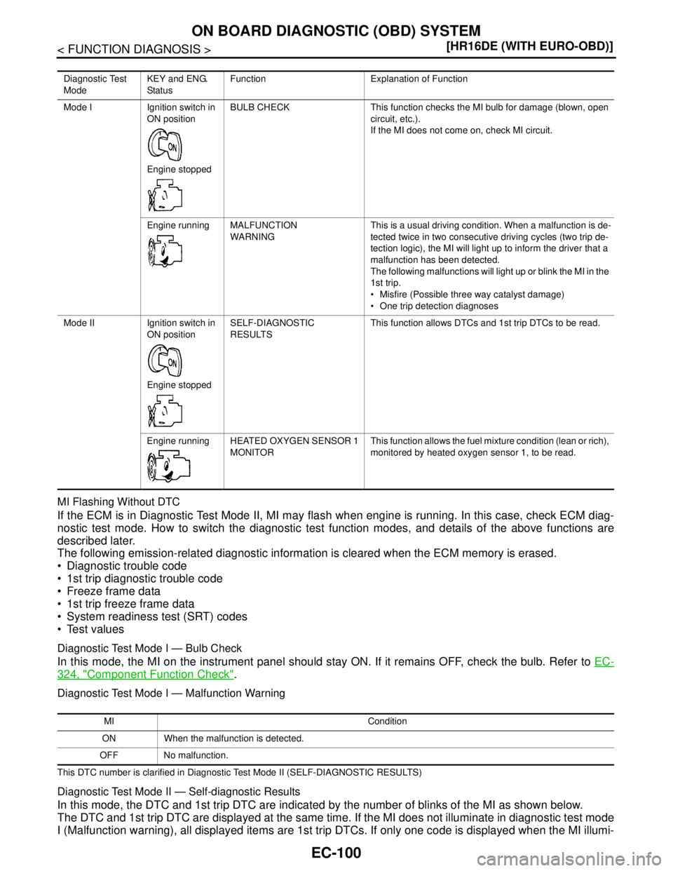
MI Flashing Without DTC
If the ECM is in Diagnostic Test Mode II, MI may flash when engine is running. In this case, check ECM diag-
nostic test mode. How to switch the diagnostic test function modes, and details of the above functions are
described later.
The following emission-related diagnostic information is cleared when the ECM memory is erased.
Diagnostic trouble code
1st trip diagnostic trouble code
Freeze frame data
1st trip freeze frame data
System readiness test (SRT) codes
Test values
Diagnostic Test Mode I — Bulb Check
In this mode, the MI on the instrument panel should stay ON. If it remains OFF, check the bulb. Refer to EC-
324, "Component Function Check".
Diagnostic Test Mode I — Malfunction Warning
This DTC number is clarified in Diagnostic Test Mode II (SELF-DIAGNOSTIC RESULTS)
Diagnostic Test Mode II — Self-diagnostic Results
In this mode, the DTC and 1st trip DTC are indicated by the number of blinks of the MI as shown below.
The DTC and 1st trip DTC are displayed at the same time. If the MI does not illuminate in diagnostic test mode
I (Malfunction warning), all displayed items are 1st trip DTCs. If only one code is displayed when the MI illumi-
Diagnostic Test
ModeKEY and ENG.
StatusFunction Explanation of Function
Mode I Ignition switch in
ON position
Engine stoppedBULB CHECK This function checks the MI bulb for damage (blown, open
circuit, etc.).
If the MI does not come on, check MI circuit.
Engine running MALFUNCTION
WARNINGThis is a usual driving condition. When a malfunction is de-
tected twice in two consecutive driving cycles (two trip de-
tection logic), the MI will light up to inform the driver that a
malfunction has been detected.
The following malfunctions will light up or blink the MI in the
1st trip.
Misfire (Possible three way catalyst damage)
One trip detection diagnoses
Mode II Ignition switch in
ON position
Engine stoppedSELF-DIAGNOSTIC
RESULTSThis function allows DTCs and 1st trip DTCs to be read.
Engine running HEATED OXYGEN SENSOR 1
MONITORThis function allows the fuel mixture condition (lean or rich),
monitored by heated oxygen sensor 1, to be read.
MI Condition
ON When the malfunction is detected.
OFF No malfunction.
Page 1453 of 5883
EC-104
< FUNCTION DIAGNOSIS >[HR16DE (WITH EURO-OBD)]
ON BOARD DIAGNOSTIC (OBD) SYSTEM
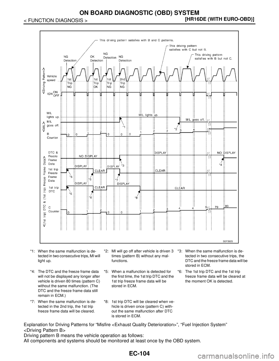
Explanation for Driving Patterns for “Misfire
Driving pattern B means the vehicle operation as follows:
All components and systems should be monitored at least once by the OBD system.
*1: When the same malfunction is de-
tected in two consecutive trips, MI will
light up.*2: MI will go off after vehicle is driven 3
times (pattern B) without any mal-
functions.*3: When the same malfunction is de-
tected in two consecutive trips, the
DTC and the freeze frame data will be
stored in ECM.
*4: The DTC and the freeze frame data
will not be displayed any longer after
vehicle is driven 80 times (pattern C)
without the same malfunction. (The
DTC and the freeze frame data still
remain in ECM.)*5: When a malfunction is detected for
the first time, the 1st trip DTC and the
1st trip freeze frame data will be
stored in ECM.*6: The 1st trip DTC and the 1st trip
freeze frame data will be cleared at
the moment OK is detected.
*7: When the same malfunction is de-
tected in the 2nd trip, the 1st trip
freeze frame data will be cleared.*8: 1st trip DTC will be cleared when ve-
hicle is driven once (pattern C) with-
out the same malfunction after DTC
is stored in ECM.
SEF392S
Page 1455 of 5883
EC-106
< FUNCTION DIAGNOSIS >[HR16DE (WITH EURO-OBD)]
ON BOARD DIAGNOSTIC (OBD) SYSTEM
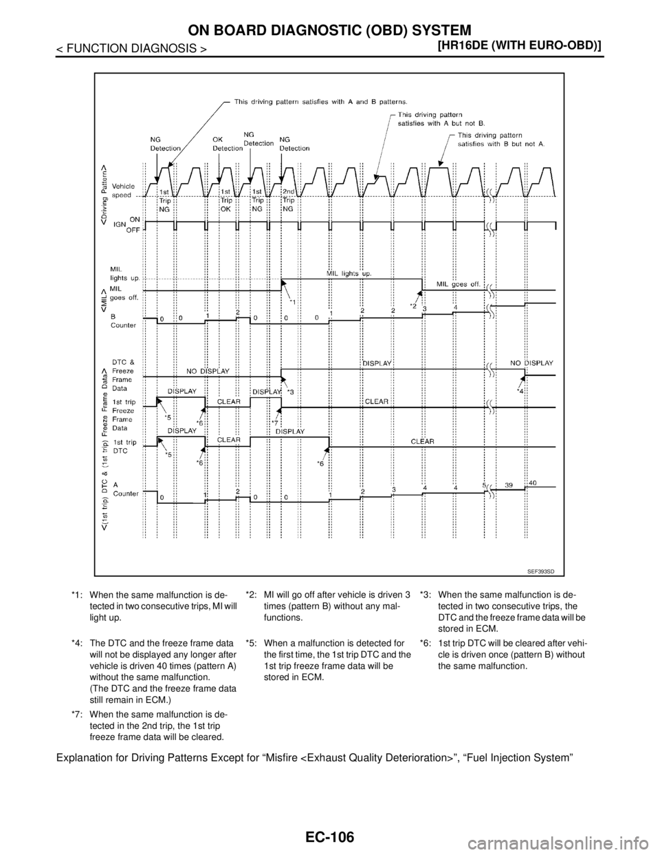
Explanation for Driving Patterns Except for “Misfire
*1: When the same malfunction is de-
tected in two consecutive trips, MI will
light up.*2: MI will go off after vehicle is driven 3
times (pattern B) without any mal-
functions.*3: When the same malfunction is de-
tected in two consecutive trips, the
DTC and the freeze frame data will be
stored in ECM.
*4: The DTC and the freeze frame data
will not be displayed any longer after
vehicle is driven 40 times (pattern A)
without the same malfunction.
(The DTC and the freeze frame data
still remain in ECM.)*5: When a malfunction is detected for
the first time, the 1st trip DTC and the
1st trip freeze frame data will be
stored in ECM.*6: 1st trip DTC will be cleared after vehi-
cle is driven once (pattern B) without
the same malfunction.
*7: When the same malfunction is de-
tected in the 2nd trip, the 1st trip
freeze frame data will be cleared.
SEF393SD
Page 1460 of 5883
ON BOARD DIAGNOSTIC (OBD) SYSTEM
EC-111
< FUNCTION DIAGNOSIS >[HR16DE (WITH EURO-OBD)]
C
D
E
F
G
H
I
J
K
L
MA
EC
N
P O
CLSD THL POS ON/OFF Indicates idle position [ON/OFF] computed by
ECM according to the accelerator pedal position
sensor signal.
AIR COND SIG ON/OFF Indicates [ON/OFF] condition of the air condition-
er switch as determined by the air conditioner sig-
nal.
P/N POSI SW ON/OFF Indicates [ON/OFF] condition from the park/neu-
tral position (PNP) switch signal.
PW/ST SIGNAL ON/OFF [ON/OFF] condition of the power steering system
(determined by the signal sent from EPS control
unit) is indicated.
LOAD SIGNAL ON/OFF Indicates [ON/OFF] condition from the electrical
load signal.
ON: Rear window defogger switch is ON and/or
lighting switch is in 2nd position.
OFF: Both rear window defogger switch and light-
ing switch are OFF.
IGNITION SW ON/OFF Indicates [ON/OFF] condition from ignition switch
signal.
CLUTCH P/P SW ON/OFF Indicates [ON/OFF] condition from the clutch
switch signal.
HEATER FAN SW ON/OFF Indicates [ON/OFF] condition from the heater fan
switch signal.
BRAKE SW ON/OFF Indicates [ON/OFF] condition from the stop lamp
switch signal.
INJ PULSE-B1 msec Indicates the actual fuel injection pulse width
compensated by ECM according to the input sig-
nals. When the engine is stopped, a certain
computed value is indicated.
IGN TIMING BTDC Indicates the ignition timing computed by ECM
according to the input signals. When the engine is stopped, a certain
value is indicated.
CAL/LD VALUE % “Calculated load value” indicates the value of the
current air flow divided by peak air flow.
MASS AIRFLOW g·m/s Indicates the mass air flow computed by ECM ac-
cording to the signal voltage of the mass air flow
sensor.
PURG VOL C/V % Indicates the EVAP canister purge volume con-
trol solenoid valve control value computed by the
ECM according to the input signals.
The opening becomes larger as the value in-
creases.
INT/V TIM (B1)°CA Indicates [°CA] of intake camshaft advance an-
gle.
INT/V SOL-B1
% The control value of the intake valve timing con-
trol solenoid valve (determined by ECM accord-
ing to the input signals) is indicated.
The advance angle becomes larger as the value
increases.
AIR COND RLY ON/OFF The air conditioner relay control condition (deter-
mined by ECM according to the input signals) is
indicated.
FUEL PUMP RLY ON/OFF Indicates the fuel pump relay control condition
determined by ECM according to the input sig-
nals.
THRTL RELAY ON/OFF Indicates the throttle control motor relay control
condition determined by the ECM according to
the input signals. Monitored item Unit Description Remarks
Page 1462 of 5883
ON BOARD DIAGNOSTIC (OBD) SYSTEM
EC-113
< FUNCTION DIAGNOSIS >[HR16DE (WITH EURO-OBD)]
C
D
E
F
G
H
I
J
K
L
MA
EC
N
P O
NOTE:
Any monitored item that does not match the vehicle being diagnosed is deleted from the display automatically.
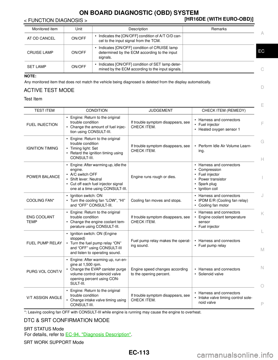
ACTIVE TEST MODE
Test Item
*: Leaving cooling fan OFF with CONSULT-III while engine is running may cause the engine to overheat.
DTC & SRT CONFIRMATION MODE
SRT STATUS Mode
For details, refer to EC-94, "Diagnosis Description".
SRT WORK SUPPORT Mode
AT OD CANCEL ON/OFF Indicates the [ON/OFF] condition of A/T O/D can-
cel to the input signal from the TCM.
CRUISE LAMP ON/OFF Indicates [ON/OFF] condition of CRUISE lamp
determined by the ECM according to the input
signals.
SET LAMP ON/OFF Indicates [ON/OFF] condition of SET lamp deter-
mined by the ECM according to the input signals. Monitored item Unit Description Remarks
TEST ITEM CONDITION JUDGEMENT CHECK ITEM (REMEDY)
FUEL INJECTION Engine: Return to the original
trouble condition
Change the amount of fuel injec-
tion using CONSULT-III.If trouble symptom disappears, see
CHECK ITEM. Harness and connectors
Fuel injector
Heated oxygen sensor 1
IGNITION TIMING Engine: Return to the original
trouble condition
Timing light: Set
Retard the ignition timing using
CONSULT-III.If trouble symptom disappears, see
CHECK ITEM. Perform Idle Air Volume Learn-
ing.
POWER BALANCE Engine: After warming up, idle the
engine.
A/C switch OFF
Shift lever: Neutral
Cut off each fuel injector signal
one at a time using CONSULT-III.Engine runs rough or dies. Harness and connectors
Compression
Fuel injector
Power transistor
Spark plug
Ignition coil
COOLING FAN* Ignition switch: ON
Turn the cooling fan “LOW”, “HI”
and “OFF” CONSULT-III.Cooling fan moves and stops. Harness and connectors
IPDM E/R (Cooling fan relay)
Cooling fan motor
ENG COOLANT
TEMP Engine: Return to the original
trouble condition
Change the engine coolant tem-
perature using CONSULT-III.If trouble symptom disappears, see
CHECK ITEM. Harness and connectors
Engine coolant temperature
sensor
Fuel injector
FUEL PUMP RELAY Ignition switch: ON (Engine
stopped)
Turn the fuel pump relay “ON”
and “OFF” using CONSULT-III
and listen to operating sound.Fuel pump relay makes the operat-
ing sound. Harness and connectors
Fuel pump relay
PURG VOL CONT/V Engine: After warming up, run en-
gine at 1,500 rpm.
Change the EVAP canister purge
volume control solenoid valve
opening percent using CON-
SULT-III.Engine speed changes according
to the opening percent. Harness and connectors
Solenoid valve
V/T ASSIGN ANGLE Engine: Return to the original
trouble condition
Change intake valve timing using
CONSULT-III.If trouble symptom disappears, see
CHECK ITEM. Harness and connectors
Intake valve timing control sole-
noid valve
Page 1465 of 5883
EC-116
< COMPONENT DIAGNOSIS >[HR16DE (WITH EURO-OBD)]
TROUBLE DIAGNOSIS - SPECIFICATION VALUE
COMPONENT DIAGNOSIS
TROUBLE DIAGNOSIS - SPECIFICATION VALUE
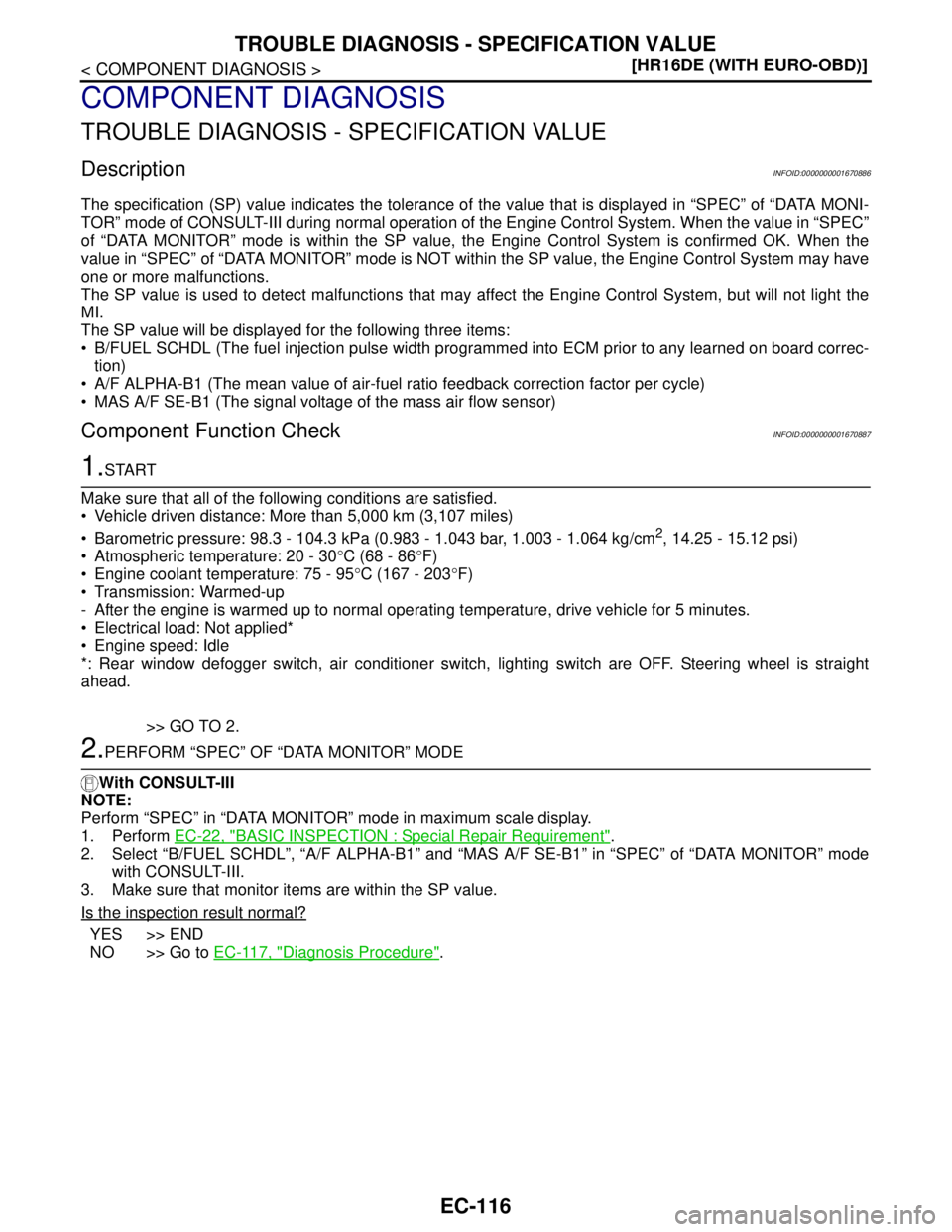
DescriptionINFOID:0000000001670886
The specification (SP) value indicates the tolerance of the value that is displayed in “SPEC” of “DATA MONI-
TOR” mode of CONSULT-III during normal operation of the Engine Control System. When the value in “SPEC”
of “DATA MONITOR” mode is within the SP value, the Engine Control System is confirmed OK. When the
value in “SPEC” of “DATA MONITOR” mode is NOT within the SP value, the Engine Control System may have
one or more malfunctions.
The SP value is used to detect malfunctions that may affect the Engine Control System, but will not light the
MI.
The SP value will be displayed for the following three items:
B/FUEL SCHDL (The fuel injection pulse width programmed into ECM prior to any learned on board correc-
tion)
A/F ALPHA-B1 (The mean value of air-fuel ratio feedback correction factor per cycle)
MAS A/F SE-B1 (The signal voltage of the mass air flow sensor)
Component Function CheckINFOID:0000000001670887
1.START
Make sure that all of the following conditions are satisfied.
Vehicle driven distance: More than 5,000 km (3,107 miles)
Barometric pressure: 98.3 - 104.3 kPa (0.983 - 1.043 bar, 1.003 - 1.064 kg/cm
2, 14.25 - 15.12 psi)
Atmospheric temperature: 20 - 30°C (68 - 86°F)
Engine coolant temperature: 75 - 95°C (167 - 203°F)
Transmission: Warmed-up
- After the engine is warmed up to normal operating temperature, drive vehicle for 5 minutes.
Electrical load: Not applied*
Engine speed: Idle
*: Rear window defogger switch, air conditioner switch, lighting switch are OFF. Steering wheel is straight
ahead.
>> GO TO 2.
2.PERFORM “SPEC” OF “DATA MONITOR” MODE
With CONSULT-III
NOTE:
Perform “SPEC” in “DATA MONITOR” mode in maximum scale display.
1. Perform EC-22, "
BASIC INSPECTION : Special Repair Requirement".
2. Select “B/FUEL SCHDL”, “A/F ALPHA-B1” and “MAS A/F SE-B1” in “SPEC” of “DATA MONITOR” mode
with CONSULT-III.
3. Make sure that monitor items are within the SP value.
Is the inspection result normal?
YES >> END
NO >> Go to EC-117, "
Diagnosis Procedure".
Page 1528 of 5883
P0171 FUEL INJECTION SYSTEM FUNCTION
EC-179
< COMPONENT DIAGNOSIS >[HR16DE (WITH EURO-OBD)]
C
D
E
F
G
H
I
J
K
L
MA
EC
N
P O
P0171 FUEL INJECTION SYSTEM FUNCTION
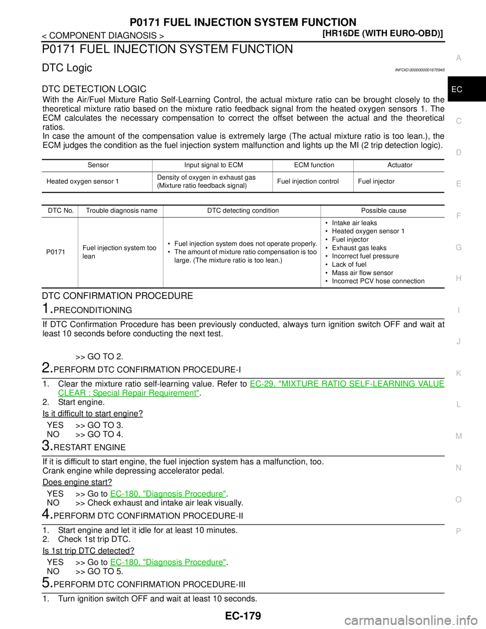
DTC LogicINFOID:0000000001670945
DTC DETECTION LOGIC
With the Air/Fuel Mixture Ratio Self-Learning Control, the actual mixture ratio can be brought closely to the
theoretical mixture ratio based on the mixture ratio feedback signal from the heated oxygen sensors 1. The
ECM calculates the necessary compensation to correct the offset between the actual and the theoretical
ratios.
In case the amount of the compensation value is extremely large (The actual mixture ratio is too lean.), the
ECM judges the condition as the fuel injection system malfunction and lights up the MI (2 trip detection logic).
DTC CONFIRMATION PROCEDURE
1.PRECONDITIONING
If DTC Confirmation Procedure has been previously conducted, always turn ignition switch OFF and wait at
least 10 seconds before conducting the next test.
>> GO TO 2.
2.PERFORM DTC CONFIRMATION PROCEDURE-I
1. Clear the mixture ratio self-learning value. Refer to EC-29, "
MIXTURE RATIO SELF-LEARNING VALUE
CLEAR : Special Repair Requirement".
2. Start engine.
Is it difficult to start engine?
YES >> GO TO 3.
NO >> GO TO 4.
3.RESTART ENGINE
If it is difficult to start engine, the fuel injection system has a malfunction, too.
Crank engine while depressing accelerator pedal.
Does engine start?
YES >> Go to EC-180, "Diagnosis Procedure".
NO >> Check exhaust and intake air leak visually.
4.PERFORM DTC CONFIRMATION PROCEDURE-II
1. Start engine and let it idle for at least 10 minutes.
2. Check 1st trip DTC.
Is 1st trip DTC detected?
YES >> Go to EC-180, "Diagnosis Procedure".
NO >> GO TO 5.
5.PERFORM DTC CONFIRMATION PROCEDURE-III
1. Turn ignition switch OFF and wait at least 10 seconds.
Sensor Input signal to ECM ECM function Actuator
Heated oxygen sensor 1Density of oxygen in exhaust gas
(Mixture ratio feedback signal)Fuel injection control Fuel injector
DTC No. Trouble diagnosis name DTC detecting condition Possible cause
P0171Fuel injection system too
lean Fuel injection system does not operate properly.
The amount of mixture ratio compensation is too
large. (The mixture ratio is too lean.) Intake air leaks
Heated oxygen sensor 1
Fuel injector
Exhaust gas leaks
Incorrect fuel pressure
Lack of fuel
Mass air flow sensor
Incorrect PCV hose connection
Page 1532 of 5883
P0172 FUEL INJECTION SYSTEM FUNCTION
EC-183
< COMPONENT DIAGNOSIS >[HR16DE (WITH EURO-OBD)]
C
D
E
F
G
H
I
J
K
L
MA
EC
N
P O
P0172 FUEL INJECTION SYSTEM FUNCTION
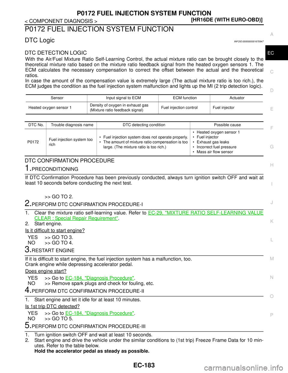
DTC LogicINFOID:0000000001670947
DTC DETECTION LOGIC
With the Air/Fuel Mixture Ratio Self-Learning Control, the actual mixture ratio can be brought closely to the
theoretical mixture ratio based on the mixture ratio feedback signal from the heated oxygen sensors 1. The
ECM calculates the necessary compensation to correct the offset between the actual and the theoretical
ratios.
In case the amount of the compensation value is extremely large (The actual mixture ratio is too rich.), the
ECM judges the condition as the fuel injection system malfunction and lights up the MI (2 trip detection logic).
DTC CONFIRMATION PROCEDURE
1.PRECONDITIONING
If DTC Confirmation Procedure has been previously conducted, always turn ignition switch OFF and wait at
least 10 seconds before conducting the next test.
>> GO TO 2.
2.PERFORM DTC CONFIRMATION PROCEDURE-I
1. Clear the mixture ratio self-learning value. Refer to EC-29, "
MIXTURE RATIO SELF-LEARNING VALUE
CLEAR : Special Repair Requirement".
2. Start engine.
Is it difficult to start engine?
YES >> GO TO 3.
NO >> GO TO 4.
3.RESTART ENGINE
If it is difficult to start engine, the fuel injection system has a malfunction, too.
Crank engine while depressing accelerator pedal.
Does engine start?
YES >> Go to EC-184, "Diagnosis Procedure".
NO >> Remove spark plugs and check for fouling, etc.
4.PERFORM DTC CONFIRMATION PROCEDURE-II
1. Start engine and let it idle for at least 10 minutes.
Is 1st trip DTC detected?
YES >> Go to EC-184, "Diagnosis Procedure".
NO >> GO TO 5.
5.PERFORM DTC CONFIRMATION PROCEDURE-III
1. Turn ignition switch OFF and wait at least 10 seconds.
2. Start engine and drive the vehicle under the similar conditions to (1st trip) Freeze Frame Data for 10 min-
utes. Refer to the table below.
Hold the accelerator pedal as steady as possible.
Sensor Input signal to ECM ECM function Actuator
Heated oxygen sensor 1Density of oxygen in exhaust gas
(Mixture ratio feedback signal)Fuel injection control Fuel injector
DTC No. Trouble diagnosis name DTC detecting condition Possible cause
P0172Fuel injection system too
rich Fuel injection system does not operate properly.
The amount of mixture ratio compensation is too
large. (The mixture ratio is too rich.) Heated oxygen sensor 1
Fuel injector
Exhaust gas leaks
Incorrect fuel pressure
Mass air flow sensor