2007 NISSAN TIIDA light system
[x] Cancel search: light systemPage 553 of 5883

DEF-2
PASSENGER SIDE DOOR MIRROR DEFOG-
GER DOES NOT OPERATE. ............................
33
Diagnosis Procedure ..............................................33
REAR WINDOW DEFOGGER SWITCH DOES
NOT LIGHT, BUT REAR WINDOW DEFOG-
GER OPERATES ...............................................
34
Diagnosis Procedure ..............................................34
PRECAUTION .............................................35
PRECAUTIONS .................................................35
Supplemental Restraint System (SRS) "AIR BAG"
and "SEAT BELT PRE-TENSIONER" ....................
35
ON-VEHICLE REPAIR ...............................36
FILAMENT .........................................................36
Inspection and Repair .............................................36
CONDENSER ....................................................38
Exploded View ........................................................38
Removal and Installation .........................................38
Page 630 of 5883

WARNING FUNCTION
DLK-41
< FUNCTION DIAGNOSIS >[WITH I-KEY, WITHOUT SUPER LOCK]
C
D
E
F
G
H
I
J
L
MA
B
DLK
N
O
P
KEY WARNING LAMP & LOCK WARNING LAMP
The key indicator and lock indicator indicates Intelligent Key system status.
Operation Condition
BACK DOOR/TRUNK OPEN WARNING OPERATION
When back door (hatchback) or trunk lid (sedan) opener switch is operated, when door lock is locked with door
lock and unlock switch, speed sensing lock or only driver side is unlocked with anti-hijack function, the buzzer
(built in combination meter) will sound.
KEY REMINDER OPERATION
The buzzer (combination meter) will sound and the doors will not lock if the door lock and unlock switch is
pressed while the driver door is open and mechanical key is inserted into ignition key cylinder.
The buzzer (combination meter) will sound and the doors will not lock if the door lock and unlock switch is
pressed while any door other than the driver door is open.
Door lock op-
eration warn-
ingRequest
switch opera-
tionWhen request switch is pushed (lock op-
eration) under the following conditions.
Door switch: ON (Any door is open).
Ignition switch is in ACC or OFF posi-
tion or ignition knob is pressed in
LOCK position or mechanical key is
inserted into ignition key cylinder.
Intelligent Key is inside vehicle.——Active for 2
seconds
(pipipi···)
Intelligent Key
button opera-
tionWhen Intelligent Key button is pushed
(lock operation) under the following con-
ditions.
Door switch: ON (Any door is open).
Ignition switch is in ACC or OFF posi-
tion or ignition knob is pressed in
LOCK position or mechanical key is
inserted into ignition key cylinder.——Active for 2
seconds
(pipipi···)
Intelligent Key low battery
warningWhen Intelligent Key battery voltage is
low, Intelligent Key unit is detected after
ignition switch is turned ON.“KEY”
(GREEN blink-
ing for 30 sec-
onds)—— Warning/Information functions Operation conditions Warning lampWarning chime
Combination
meter buzzerIntelligent Key
warning buzz-
er(s)
Behavior of lamps Operation condition
KEYGREENLightingAll the following conditions are satisfied.
Ignition knob is pushed in LOCK position. (Ignition knob switch is ON)
Ignition key is removed from ignition key cylinder. (Key switch is OFF)
Intelligent Key is detected inside of the vehicle.
KEY RED lighting/blinking conditions are not satisfied.
Blinking while Intelligent Key low battery warning is operating.
REDLightingAll the following conditions are satisfied.
Ignition knob is pushed. (Ignition knob switch is ON)
Ignition key is removed from ignition key cylinder. (Key switch is OFF)
Intelligent Key is not detected inside of the vehicle.
BlinkingAll the following conditions are satisfied.
Take away warning is operating.
KEY RED lighting condition is not satisfied.
LOCK Blinking While OFF position warning is operating.
KEY(RED) and LOCK lightingAll the following conditions are satisfied.
Ignition switch is ON.
Steering lock ID is NG.
Page 855 of 5883
DLK-266
< FUNCTION DIAGNOSIS >[WITH I-KEY & SUPER LOCK]
WARNING FUNCTION
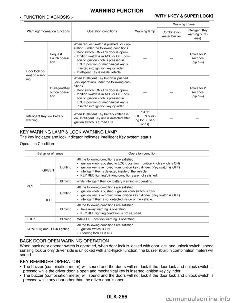
KEY WARNING LAMP & LOCK WARNING LAMP
The key indicator and lock indicator indicates Intelligent Key system status.
Operation Condition
BACK DOOR OPEN WARNING OPERATION
When back door opener switch is operated, when door lock is locked with door lock and unlock switch, speed
sensing lock or only driver side is unlocked with anti-hijack function, the buzzer (built in combination meter) will
sound.
KEY REMINDER OPERATION
The buzzer (combination meter) will sound and the doors will not lock if the door lock and unlock switch is
pressed while the driver door is open and mechanical key is inserted ignition key cylinder.
The buzzer (combination meter) will sound and the doors will not lock if the door lock and unlock switch is
pressed while any door other than the driver door is open.
Door lock op-
eration warn-
ingRequest
switch opera-
tionWhen request switch is pushed (lock op-
eration) under the following conditions.
Door switch: ON (Any door is open).
Ignition switch is in ACC or OFF posi-
tion or ignition knob is pressed in
LOCK position or mechanical key is
inserted into ignition key cylinder.
Intelligent Key is inside vehicle.——Active for 2
seconds
(pipipi···)
Intelligent Key
button opera-
tionWhen Intelligent Key button is pushed
(lock operation) under the following con-
ditions.
Door switch: ON (Any door is open).
Ignition switch is in ACC or OFF posi-
tion or ignition knob is pressed in
LOCK position or mechanical key is
inserted into ignition key cylinder.——Active for 2
seconds
(pipipi···)
Intelligent Key low battery
warningWhen Intelligent Key battery voltage is
low, Intelligent Key unit is detected after
ignition switch is turned ON.“KEY”
(GREEN blink-
ing for 30 sec-
onds)—— Warning/Information functions Operation conditions Warning lampWarning chime
Combination
meter buzzerIntelligent Key
warning buzz-
er(s)
Behavior of lamps Operation condition
KEYGREENLightingAll the following conditions are satisfied.
Ignition knob is pushed in LOCK position. (Ignition knob switch is ON)
Ignition key is removed from ignition key cylinder. (Key switch is OFF)
Intelligent Key is detected inside of the vehicle.
KEY RED lighting/blinking conditions are not satisfied.
Blinking while Intelligent Key low battery warning is operating.
REDLightingAll the following conditions are satisfied.
Ignition knob is pushed. (Ignition knob switch is ON)
Ignition key is removed from ignition key cylinder. (Key switch is OFF)
Intelligent Key is not detected inside of the vehicle.
BlinkingAll the following conditions are satisfied.
Take away warning is operating.
KEY RED lighting condition is not satisfied.
LOCK Blinking While OFF position warning is operating.
KEY(RED) and LOCK lightingAll the following conditions are satisfied.
Ignition switch is ON.
Steering lock ID is NG.
Page 1376 of 5883
INSPECTION AND ADJUSTMENT
EC-27
< BASIC INSPECTION >[HR16DE (WITH EURO-OBD)]
C
D
E
F
G
H
I
J
K
L
MA
EC
N
P O
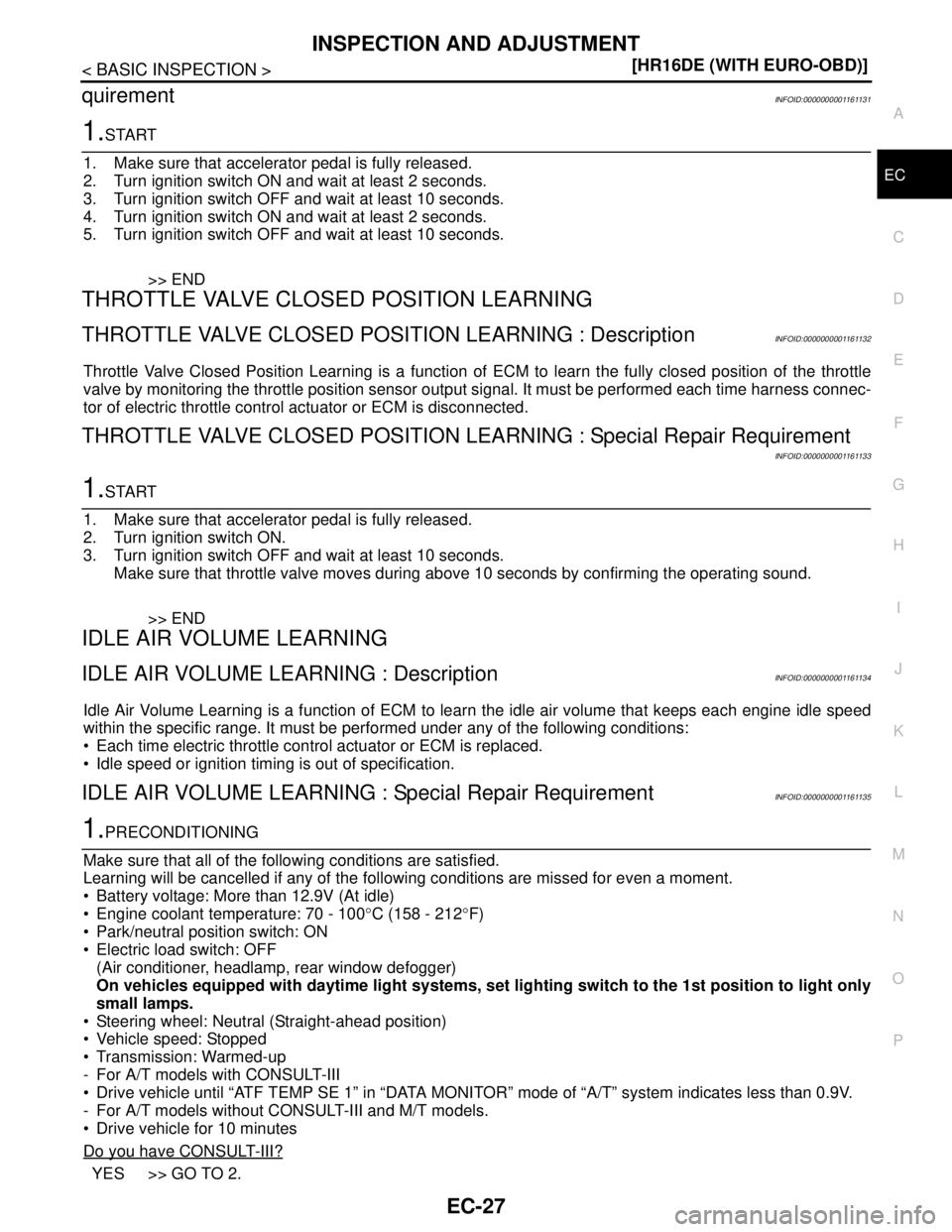
quirementINFOID:0000000001161131
1.START
1. Make sure that accelerator pedal is fully released.
2. Turn ignition switch ON and wait at least 2 seconds.
3. Turn ignition switch OFF and wait at least 10 seconds.
4. Turn ignition switch ON and wait at least 2 seconds.
5. Turn ignition switch OFF and wait at least 10 seconds.
>> END
THROTTLE VALVE CLOSED POSITION LEARNING
THROTTLE VALVE CLOSED POSITION LEARNING : DescriptionINFOID:0000000001161132
Throttle Valve Closed Position Learning is a function of ECM to learn the fully closed position of the throttle
valve by monitoring the throttle position sensor output signal. It must be performed each time harness connec-
tor of electric throttle control actuator or ECM is disconnected.
THROTTLE VALVE CLOSED POSITION LEARNING : Special Repair Requirement
INFOID:0000000001161133
1.START
1. Make sure that accelerator pedal is fully released.
2. Turn ignition switch ON.
3. Turn ignition switch OFF and wait at least 10 seconds.
Make sure that throttle valve moves during above 10 seconds by confirming the operating sound.
>> END
IDLE AIR VOLUME LEARNING
IDLE AIR VOLUME LEARNING : DescriptionINFOID:0000000001161134
Idle Air Volume Learning is a function of ECM to learn the idle air volume that keeps each engine idle speed
within the specific range. It must be performed under any of the following conditions:
Each time electric throttle control actuator or ECM is replaced.
Idle speed or ignition timing is out of specification.
IDLE AIR VOLUME LEARNING : Special Repair RequirementINFOID:0000000001161135
1.PRECONDITIONING
Make sure that all of the following conditions are satisfied.
Learning will be cancelled if any of the following conditions are missed for even a moment.
Battery voltage: More than 12.9V (At idle)
Engine coolant temperature: 70 - 100°C (158 - 212°F)
Park/neutral position switch: ON
Electric load switch: OFF
(Air conditioner, headlamp, rear window defogger)
On vehicles equipped with daytime light systems, set lighting switch to the 1st position to light only
small lamps.
Steering wheel: Neutral (Straight-ahead position)
Vehicle speed: Stopped
Transmission: Warmed-up
- For A/T models with CONSULT-III
Drive vehicle until “ATF TEMP SE 1” in “DATA MONITOR” mode of “A/T” system indicates less than 0.9V.
- For A/T models without CONSULT-III and M/T models.
Drive vehicle for 10 minutes
Do you have CONSULT-III?
YES >> GO TO 2.
Page 1411 of 5883
EC-62
< FUNCTION DIAGNOSIS >[HR16DE (WITH EURO-OBD)]
AUTOMATIC SPEED CONTROL DEVICE (ASCD)
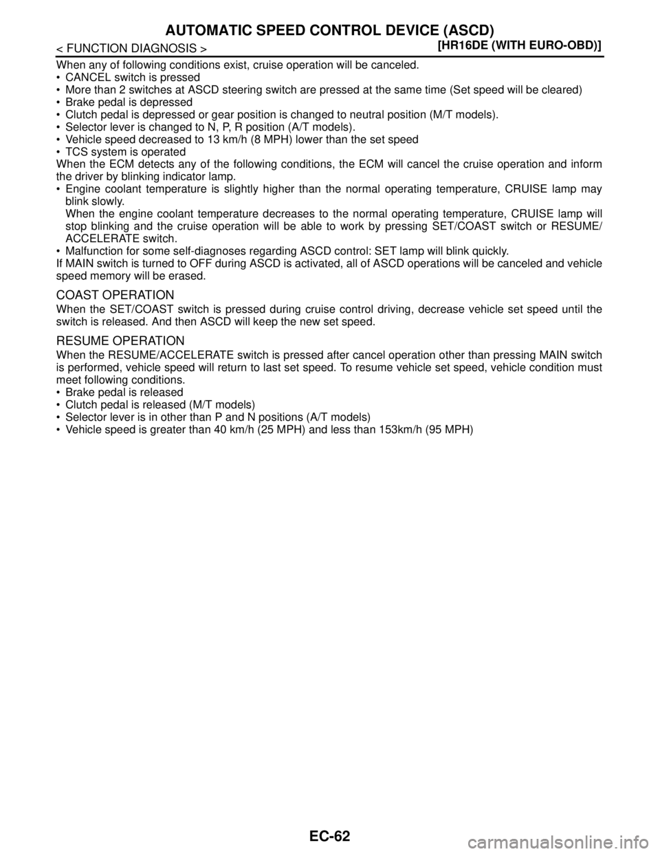
When any of following conditions exist, cruise operation will be canceled.
CANCEL switch is pressed
More than 2 switches at ASCD steering switch are pressed at the same time (Set speed will be cleared)
Brake pedal is depressed
Clutch pedal is depressed or gear position is changed to neutral position (M/T models).
Selector lever is changed to N, P, R position (A/T models).
Vehicle speed decreased to 13 km/h (8 MPH) lower than the set speed
TCS system is operated
When the ECM detects any of the following conditions, the ECM will cancel the cruise operation and inform
the driver by blinking indicator lamp.
Engine coolant temperature is slightly higher than the normal operating temperature, CRUISE lamp may
blink slowly.
When the engine coolant temperature decreases to the normal operating temperature, CRUISE lamp will
stop blinking and the cruise operation will be able to work by pressing SET/COAST switch or RESUME/
ACCELERATE switch.
Malfunction for some self-diagnoses regarding ASCD control: SET lamp will blink quickly.
If MAIN switch is turned to OFF during ASCD is activated, all of ASCD operations will be canceled and vehicle
speed memory will be erased.
COAST OPERATION
When the SET/COAST switch is pressed during cruise control driving, decrease vehicle set speed until the
switch is released. And then ASCD will keep the new set speed.
RESUME OPERATION
When the RESUME/ACCELERATE switch is pressed after cancel operation other than pressing MAIN switch
is performed, vehicle speed will return to last set speed. To resume vehicle set speed, vehicle condition must
meet following conditions.
Brake pedal is released
Clutch pedal is released (M/T models)
Selector lever is in other than P and N positions (A/T models)
Vehicle speed is greater than 40 km/h (25 MPH) and less than 153km/h (95 MPH)
Page 1443 of 5883
EC-94
< FUNCTION DIAGNOSIS >[HR16DE (WITH EURO-OBD)]
ON BOARD DIAGNOSTIC (OBD) SYSTEM
ON BOARD DIAGNOSTIC (OBD) SYSTEM
Diagnosis DescriptionINFOID:0000000001161171
INTRODUCTION
The ECM has an on board diagnostic system, which detects malfunctions related to engine sensors or actua-
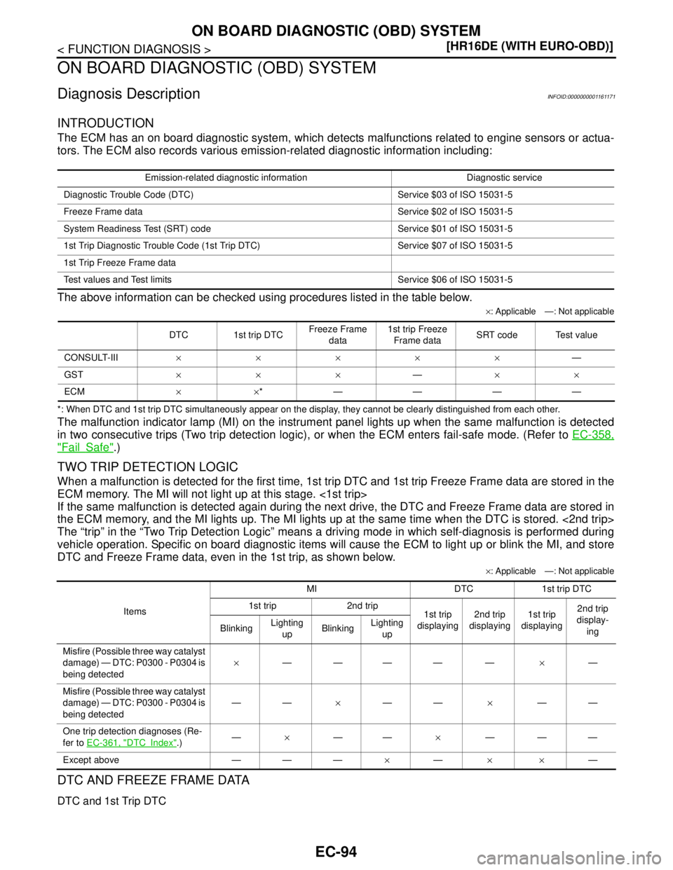
tors. The ECM also records various emission-related diagnostic information including:
The above information can be checked using procedures listed in the table below.
×: Applicable —: Not applicable
*: When DTC and 1st trip DTC simultaneously appear on the display, they cannot be clearly distinguished from each other.
The malfunction indicator lamp (MI) on the instrument panel lights up when the same malfunction is detected
in two consecutive trips (Two trip detection logic), or when the ECM enters fail-safe mode. (Refer to EC-358,
"FailSafe".)
TWO TRIP DETECTION LOGIC
When a malfunction is detected for the first time, 1st trip DTC and 1st trip Freeze Frame data are stored in the
ECM memory. The MI will not light up at this stage. <1st trip>
If the same malfunction is detected again during the next drive, the DTC and Freeze Frame data are stored in
the ECM memory, and the MI lights up. The MI lights up at the same time when the DTC is stored. <2nd trip>
The “trip” in the “Two Trip Detection Logic” means a driving mode in which self-diagnosis is performed during
vehicle operation. Specific on board diagnostic items will cause the ECM to light up or blink the MI, and store
DTC and Freeze Frame data, even in the 1st trip, as shown below.
×: Applicable —: Not applicable
DTC AND FREEZE FRAME DATA
DTC and 1st Trip DTC
Emission-related diagnostic information Diagnostic service
Diagnostic Trouble Code (DTC) Service $03 of ISO 15031-5
Freeze Frame data Service $02 of ISO 15031-5
System Readiness Test (SRT) code Service $01 of ISO 15031-5
1st Trip Diagnostic Trouble Code (1st Trip DTC) Service $07 of ISO 15031-5
1st Trip Freeze Frame data
Test values and Test limits Service $06 of ISO 15031-5
DTC 1st trip DTCFreeze Frame
data1st trip Freeze
Frame dataSRT code Test value
CONSULT-III×××××—
GST×××—××
ECM××*————
ItemsMI DTC 1st trip DTC
1st trip 2nd trip
1st trip
displaying2nd trip
displaying1st trip
displaying2nd trip
display-
ing BlinkingLighting
upBlinkingLighting
up
Misfire (Possible three way catalyst
damage) — DTC: P0300 - P0304 is
being detected×———— —×—
Misfire (Possible three way catalyst
damage) — DTC: P0300 - P0304 is
being detected——×——×——
One trip detection diagnoses (Re-
fer to EC-361, "
DTCIndex".)—×——×———
Except above — — —×—××—
Page 1444 of 5883
ON BOARD DIAGNOSTIC (OBD) SYSTEM
EC-95
< FUNCTION DIAGNOSIS >[HR16DE (WITH EURO-OBD)]
C
D
E
F
G
H
I
J
K
L
MA
EC
N
P O
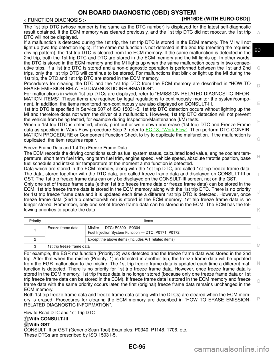
The 1st trip DTC (whose number is the same as the DTC number) is displayed for the latest self-diagnostic
result obtained. If the ECM memory was cleared previously, and the 1st trip DTC did not reoccur, the 1st trip
DTC will not be displayed.
If a malfunction is detected during the 1st trip, the 1st trip DTC is stored in the ECM memory. The MI will not
light up (two trip detection logic). If the same malfunction is not detected in the 2nd trip (meeting the required
driving pattern), the 1st trip DTC is cleared from the ECM memory. If the same malfunction is detected in the
2nd trip, both the 1st trip DTC and DTC are stored in the ECM memory and the MI lights up. In other words,
the DTC is stored in the ECM memory and the MI lights up when the same malfunction occurs in two consec-
utive trips. If a 1st trip DTC is stored and a non-diagnostic operation is performed between the 1st and 2nd
trips, only the 1st trip DTC will continue to be stored. For malfunctions that blink or light up the MI during the
1st trip, the DTC and 1st trip DTC are stored in the ECM memory.
Procedures for clearing the DTC and the 1st trip DTC from the ECM memory are described in “HOW TO
ERASE EMISSION-RELATED DIAGNOSTIC INFORMATION”.
For malfunctions in which 1st trip DTCs are displayed, refer to “EMISSION-RELATED DIAGNOSTIC INFOR-
MATION ITEMS”. These items are required by legal regulations to continuously monitor the system/compo-
nent. In addition, the items monitored non-continuously are also displayed on CONSULT-III.
1st trip DTC is specified in Service $07 of ISO 15031-5. 1st trip DTC detection occurs without lighting up the
MI and therefore does not warn the driver of a malfunction. However, 1st trip DTC detection will not prevent
the vehicle from being tested, for example during Inspection/Maintenance (I/M) tests.
When a 1st trip DTC is detected, check, print out or write down and erase (1st trip) DTC and Freeze Frame
data as specified in Work Flow procedure Step 2, refer to EC-18, "
Work Flow". Then perform DTC CONFIR-
MATION PROCEDURE or Component Function Check to try to duplicate the malfunction. If the malfunction is
duplicated, the item requires repair.
Freeze Frame Data and 1st Trip Freeze Frame Data
The ECM records the driving conditions such as fuel system status, calculated load value, engine coolant tem-
perature, short term fuel trim, long term fuel trim, engine speed, vehicle speed, absolute throttle position, base
fuel schedule and intake air temperature at the moment a malfunction is detected.
Data which are stored in the ECM memory, along with the 1st trip DTC, are called 1st trip freeze frame data.
The data, stored together with the DTC data, are called freeze frame data and displayed on CONSULT-III or
GST. The 1st trip freeze frame data can only be displayed on the CONSULT-III screen, not on the GST.
Only one set of freeze frame data (either 1st trip freeze frame data or freeze frame data) can be stored in the
ECM. 1st trip freeze frame data is stored in the ECM memory along with the 1st trip DTC. There is no priority
for 1st trip freeze frame data and it is updated each time a different 1st trip DTC is detected. However, once
freeze frame data (2nd trip detection/MI on) is stored in the ECM memory, 1st trip freeze frame data is no
longer stored. Remember, only one set of freeze frame data can be stored in the ECM. The ECM has the fol-
lowing priorities to update the data.
For example, the EGR malfunction (Priority: 2) was detected and the freeze frame data was stored in the 2nd
trip. After that when the misfire (Priority: 1) is detected in another trip, the freeze frame data will be updated
from the EGR malfunction to the misfire. The 1st trip freeze frame data is updated each time a different mal-
function is detected. There is no priority for 1st trip freeze frame data. However, once freeze frame data is
stored in the ECM memory, 1st trip freeze data is no longer stored (because only one freeze frame data or 1st
trip freeze frame data can be stored in the ECM). If freeze frame data is stored in the ECM memory and freeze
frame data with the same priority occurs later, the first (original) freeze frame data remains unchanged in the
ECM memory.
Both 1st trip freeze frame data and freeze frame data (along with the DTCs) are cleared when the ECM mem-
ory is erased. Procedures for clearing the ECM memory are described in “HOW TO ERASE EMISSION-
RELATED DIAGNOSTIC INFORMATION”.
How to Read DTC and 1st Trip DTC
With CONSULT-III
With GST
CONSULT-III or GST (Generic Scan Tool) Examples: P0340, P1148, 1706, etc.
These DTCs are prescribed by ISO 15031-5.
Priority Items
1Freeze frame data Misfire — DTC: P0300 - P0304
Fuel Injection System Function — DTC: P0171, P0172
2 Except the above items (Includes A/T related items)
3 1st trip freeze frame data
Page 1448 of 5883
ON BOARD DIAGNOSTIC (OBD) SYSTEM
EC-99
< FUNCTION DIAGNOSIS >[HR16DE (WITH EURO-OBD)]
C
D
E
F
G
H
I
J
K
L
MA
EC
N
P O How to Display SRT StatusWITH CONSULT-III
Selecting “SRT STATUS” in “DTC CONFIRMATION” mode with CONSULT-III.
For items whose SRT codes are set, a “CMPLT” is displayed on the CONSULT-III screen; for items whose
SRT codes are not set, “INCMP” is displayed.
WITH GST
Selecting Service $01 with GST (Generic Scan Tool)
NO TOOLS
A SRT code itself can not be displayed while only SRT status can be.
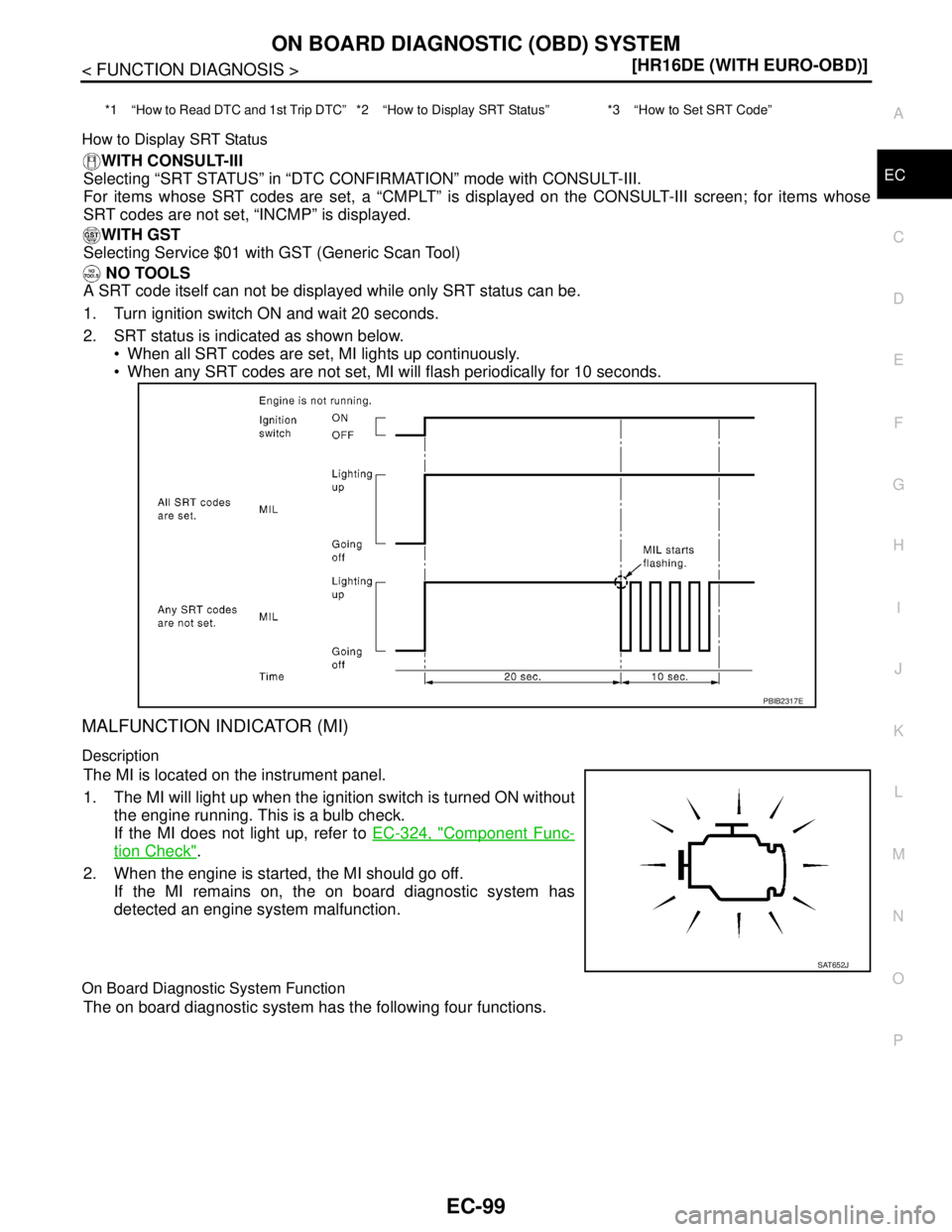
1. Turn ignition switch ON and wait 20 seconds.
2. SRT status is indicated as shown below.
When all SRT codes are set, MI lights up continuously.
When any SRT codes are not set, MI will flash periodically for 10 seconds.
MALFUNCTION INDICATOR (MI)
Description
The MI is located on the instrument panel.
1. The MI will light up when the ignition switch is turned ON without
the engine running. This is a bulb check.
If the MI does not light up, refer to EC-324, "
Component Func-
tion Check".
2. When the engine is started, the MI should go off.
If the MI remains on, the on board diagnostic system has
detected an engine system malfunction.
On Board Diagnostic System Function
The on board diagnostic system has the following four functions.
*1 “How to Read DTC and 1st Trip DTC” *2 “How to Display SRT Status” *3 “How to Set SRT Code”
PBIB2317E
SAT652J