2007 NISSAN TIIDA bulb
[x] Cancel search: bulbPage 3045 of 5883
EXL-44
< COMPONENT DIAGNOSIS >
REAR FOG LAMP CIRCUIT
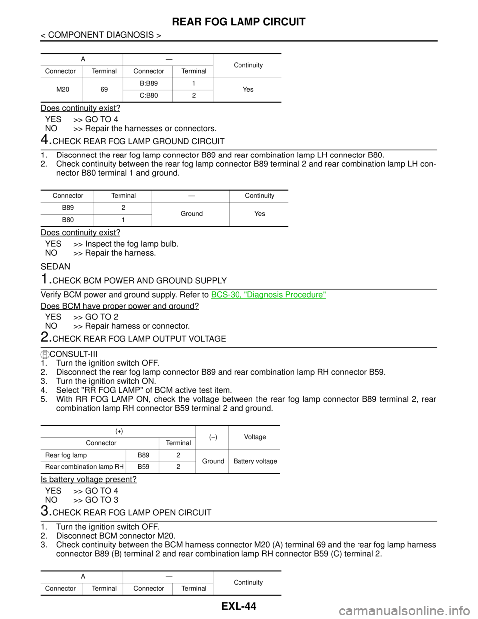
Does continuity exist?
YES >> GO TO 4
NO >> Repair the harnesses or connectors.
4.CHECK REAR FOG LAMP GROUND CIRCUIT
1. Disconnect the rear fog lamp connector B89 and rear combination lamp LH connector B80.
2. Check continuity between the rear fog lamp connector B89 terminal 2 and rear combination lamp LH con-
nector B80 terminal 1 and ground.
Does continuity exist?
YES >> Inspect the fog lamp bulb.
NO >> Repair the harness.
SEDAN
1.CHECK BCM POWER AND GROUND SUPPLY
Verify BCM power and ground supply. Refer to BCS-30, "
Diagnosis Procedure"
Does BCM have proper power and ground?
YES >> GO TO 2
NO >> Repair harness or connector.
2.CHECK REAR FOG LAMP OUTPUT VOLTAGE
CONSULT-III
1. Turn the ignition switch OFF.
2. Disconnect the rear fog lamp connector B89 and rear combination lamp RH connector B59.
3. Turn the ignition switch ON.
4. Select "RR FOG LAMP" of BCM active test item.
5. With RR FOG LAMP ON, check the voltage between the rear fog lamp connector B89 terminal 2, rear
combination lamp RH connector B59 terminal 2 and ground.
Is battery voltage present?
YES >> GO TO 4
NO >> GO TO 3
3.CHECK REAR FOG LAMP OPEN CIRCUIT
1. Turn the ignition switch OFF.
2. Disconnect BCM connector M20.
3. Check continuity between the BCM harness connector M20 (A) terminal 69 and the rear fog lamp harness
connector B89 (B) terminal 2 and rear combination lamp RH connector B59 (C) terminal 2.
A—
Continuity
Connector Terminal Connector Terminal
M20 69B:B89 1
Ye s
C:B80 2
Connector Terminal — Continuity
B89 2
Ground Yes
B80 1
(+)
(−) Voltage
Connector Terminal
Rear fog lamp B89 2
Ground Battery voltage
Rear combination lamp RH B59 2
A—
Continuity
Connector Terminal Connector Terminal
Page 3046 of 5883
REAR FOG LAMP CIRCUIT
EXL-45
< COMPONENT DIAGNOSIS >
C
D
E
F
G
H
I
J
K
MA
B
EXL
N
O
P
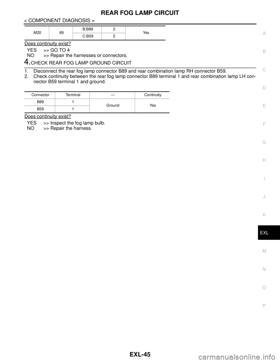
Does continuity exist?
YES >> GO TO 4
NO >> Repair the harnesses or connectors.
4.CHECK REAR FOG LAMP GROUND CIRCUIT
1. Disconnect the rear fog lamp connector B89 and rear combination lamp RH connector B59.
2. Check continuity between the rear fog lamp connector B89 terminal 1 and rear combination lamp LH con-
nector B59 terminal 1 and ground.
Does continuity exist?
YES >> Inspect the fog lamp bulb.
NO >> Repair the harness.
M20 69B:B89 2
Ye s
C:B59 2
Connector Terminal — Continuity
B89 1
Ground Yes
B59 1
Page 3049 of 5883
EXL-48
< COMPONENT DIAGNOSIS >
PARKING LAMP CIRCUIT
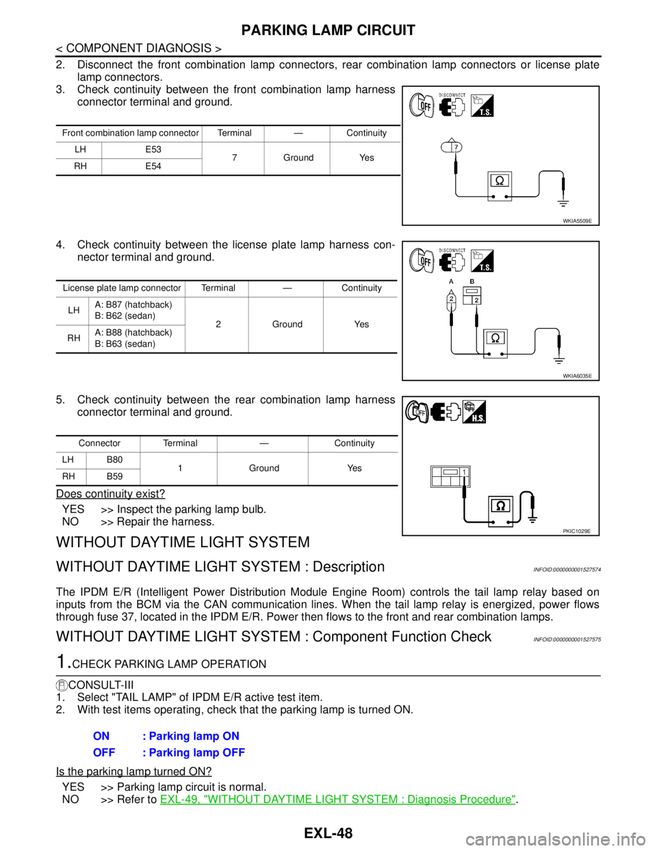
2. Disconnect the front combination lamp connectors, rear combination lamp connectors or license plate
lamp connectors.
3. Check continuity between the front combination lamp harness
connector terminal and ground.
4. Check continuity between the license plate lamp harness con-
nector terminal and ground.
5. Check continuity between the rear combination lamp harness
connector terminal and ground.
Does continuity exist?
YES >> Inspect the parking lamp bulb.
NO >> Repair the harness.
WITHOUT DAYTIME LIGHT SYSTEM
WITHOUT DAYTIME LIGHT SYSTEM : DescriptionINFOID:0000000001527574
The IPDM E/R (Intelligent Power Distribution Module Engine Room) controls the tail lamp relay based on
inputs from the BCM via the CAN communication lines. When the tail lamp relay is energized, power flows
through fuse 37, located in the IPDM E/R. Power then flows to the front and rear combination lamps.
WITHOUT DAYTIME LIGHT SYSTEM : Component Function CheckINFOID:0000000001527575
1.CHECK PARKING LAMP OPERATION
CONSULT-III
1. Select "TAIL LAMP" of IPDM E/R active test item.
2. With test items operating, check that the parking lamp is turned ON.
Is the parking lamp turned ON?
YES >> Parking lamp circuit is normal.
NO >> Refer to EXL-49, "
WITHOUT DAYTIME LIGHT SYSTEM : Diagnosis Procedure".
Front combination lamp connector Terminal — Continuity
LH E53
7GroundYes
RH E54
WKIA5509E
License plate lamp connector Terminal — Continuity
LHA: B87 (hatchback)
B: B62 (sedan)
2GroundYes
RHA: B88 (hatchback)
B: B63 (sedan)
WKIA6035E
Connector Terminal — Continuity
LH B80
1Ground Yes
RH B59
PKIC1029E
ON : Parking lamp ON
OFF : Parking lamp OFF
Page 3052 of 5883
PARKING LAMP CIRCUIT
EXL-51
< COMPONENT DIAGNOSIS >
C
D
E
F
G
H
I
J
K
MA
B
EXL
N
O
P
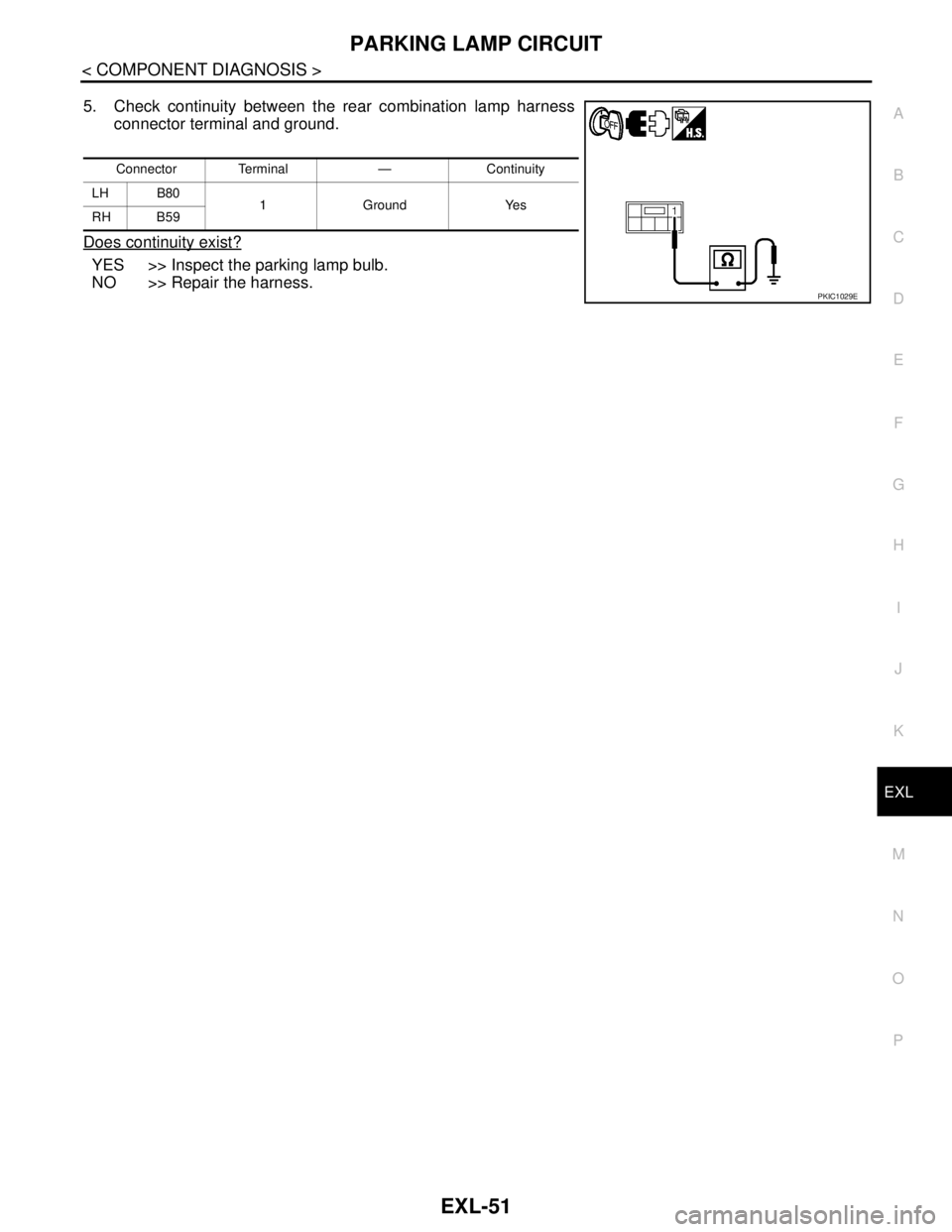
5. Check continuity between the rear combination lamp harness
connector terminal and ground.
Does continuity exist?
YES >> Inspect the parking lamp bulb.
NO >> Repair the harness.
Connector Terminal — Continuity
LH B80
1 Ground Yes
RH B59
PKIC1029E
Page 3053 of 5883
EXL-52
< COMPONENT DIAGNOSIS >
TURN SIGNAL LAMP CIRCUIT
TURN SIGNAL LAMP CIRCUIT
DescriptionINFOID:0000000001523271
The BCM monitors inputs from the combination switch to determine when to activate the turn signals. The
BCM outputs voltage directly to the left and right turn signals during turn signal operation or both during hazard
warning operation. The BCM sends a turn signal indicator request to the combination meter via the CAN com-
munication lines.
The BCM performs the fast flasher operation (fail-safe) if any bulb or harness of the turn signal lamp circuit is
open.
NOTE:
Turn signal lamps blink at normal speed when using the hazard warning lamp.
Component Function CheckINFOID:0000000001523272
1.CHECK TURN SIGNAL LAMP
CONSULT-III
1. Select "FLASHER" of BCM (FLASHER) active test item.
2. With test items operating, check that the turn signal lamp blinks.
Does the turn signal lamp blink?
YES >> Turn signal lamp circuit is normal.
NO >> Refer to EXL-52, "
Diagnosis Procedure".
Diagnosis ProcedureINFOID:0000000001523273
1.CHECK TURN SIGNAL LAMP BULB
Check the applicable lamp bulb to be sure the proper bulb standard is in use and the bulb is not open.
Is the bulb OK?
YES >> GO TO 2
NO >> Replace the bulb.
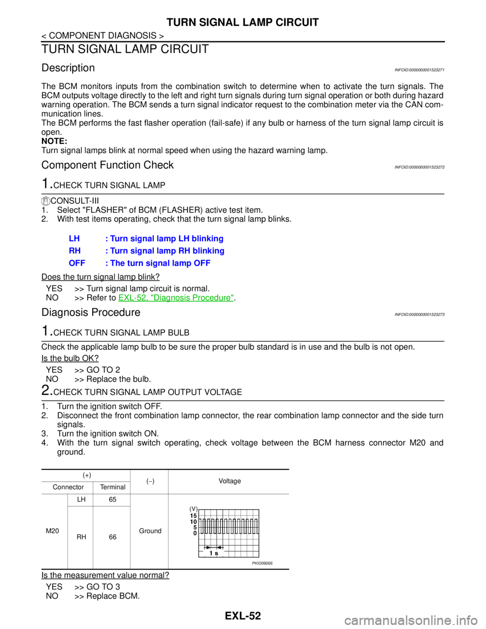
2.CHECK TURN SIGNAL LAMP OUTPUT VOLTAGE
1. Turn the ignition switch OFF.
2. Disconnect the front combination lamp connector, the rear combination lamp connector and the side turn
signals.
3. Turn the ignition switch ON.
4. With the turn signal switch operating, check voltage between the BCM harness connector M20 and
ground.
Is the measurement value normal?
YES >> GO TO 3
NO >> Replace BCM.LH : Turn signal lamp LH blinking
RH : Turn signal lamp RH blinking
OFF : The turn signal lamp OFF
(+)
(−) Voltage
Connector Terminal
M20 LH 65
Ground
RH 66
PKID0926E
Page 3074 of 5883
EXTERIOR LIGHTING SYSTEM SYMPTOMS
EXL-73
< SYMPTOM DIAGNOSIS >
C
D
E
F
G
H
I
J
K
MA
B
EXL
N
O
P
SYMPTOM DIAGNOSIS
EXTERIOR LIGHTING SYSTEM SYMPTOMS
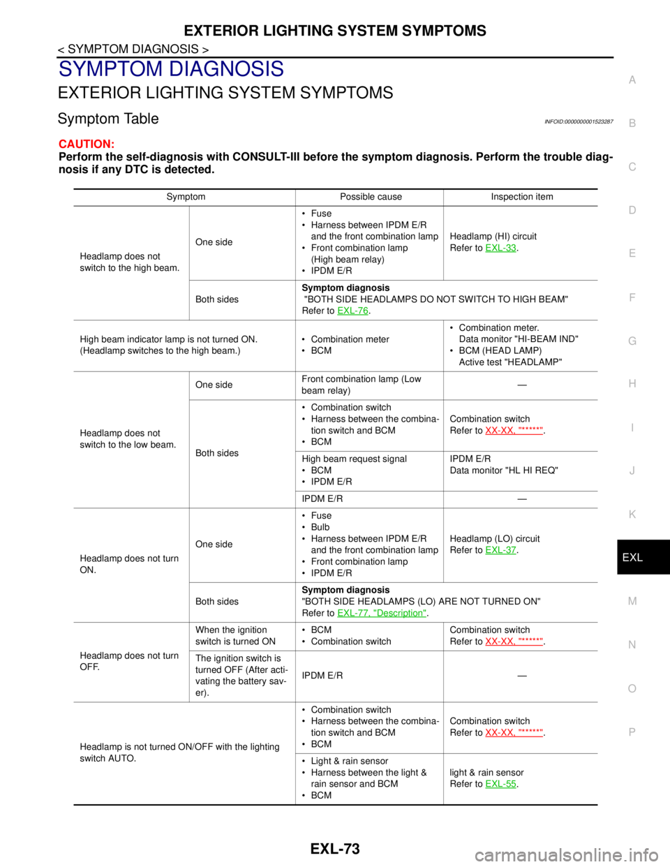
Symptom TableINFOID:0000000001523287
CAUTION:
Perform the self-diagnosis with CONSULT-III before the symptom diagnosis. Perform the trouble diag-
nosis if any DTC is detected.
Symptom Possible cause Inspection item
Headlamp does not
switch to the high beam.One sideFuse
Harness between IPDM E/R
and the front combination lamp
Front combination lamp
(High beam relay)
IPDM E/RHeadlamp (HI) circuit
Refer to EXL-33
.
Both sidesSymptom diagnosis
"BOTH SIDE HEADLAMPS DO NOT SWITCH TO HIGH BEAM"
Refer to EXL-76
.
High beam indicator lamp is not turned ON.
(Headlamp switches to the high beam.) Combination meter
BCM Combination meter.
Data monitor "HI-BEAM IND"
BCM (HEAD LAMP)
Active test "HEADLAMP"
Headlamp does not
switch to the low beam.One sideFront combination lamp (Low
beam relay)—
Both sides Combination switch
Harness between the combina-
tion switch and BCM
BCMCombination switch
Refer to XX-XX, "*****"
.
High beam request signal
BCM
IPDM E/RIPDM E/R
Data monitor "HL HI REQ"
IPDM E/R —
Headlamp does not turn
ON.One sideFuse
Bulb
Harness between IPDM E/R
and the front combination lamp
Front combination lamp
IPDM E/RHeadlamp (LO) circuit
Refer to EXL-37
.
Both sidesSymptom diagnosis
"BOTH SIDE HEADLAMPS (LO) ARE NOT TURNED ON"
Refer to EXL-77, "
Description".
Headlamp does not turn
OFF.When the ignition
switch is turned ONBCM
Combination switchCombination switch
Refer to XX-XX, "*****"
.
The ignition switch is
turned OFF (After acti-
vating the battery sav-
er).IPDM E/R —
Headlamp is not turned ON/OFF with the lighting
switch AUTO. Combination switch
Harness between the combina-
tion switch and BCM
BCMCombination switch
Refer to XX-XX, "*****"
.
Light & rain sensor
Harness between the light &
rain sensor and BCM
BCMlight & rain sensor
Refer to EXL-55
.
Page 3075 of 5883
EXL-74
< SYMPTOM DIAGNOSIS >
EXTERIOR LIGHTING SYSTEM SYMPTOMS
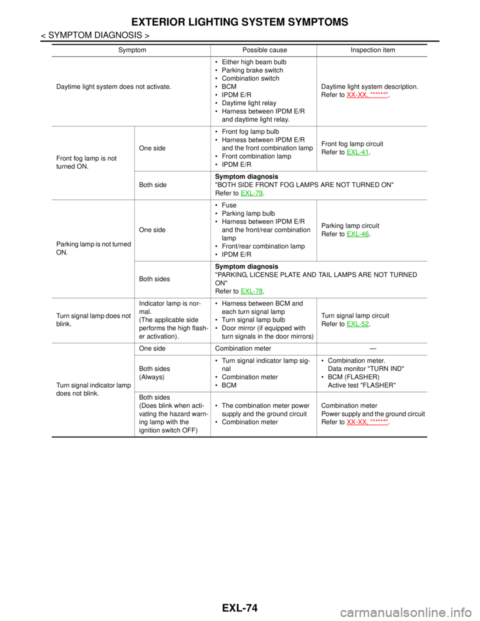
Daytime light system does not activate. Either high beam bulb
Parking brake switch
Combination switch
BCM
IPDM E/R
Daytime light relay
Harness between IPDM E/R
and daytime light relay.Daytime light system description.
Refer to XX-XX, "*****"
.
Front fog lamp is not
turned ON.One side Front fog lamp bulb
Harness between IPDM E/R
and the front combination lamp
Front combination lamp
IPDM E/RFront fog lamp circuit
Refer to EXL-41
.
Both sideSymptom diagnosis
"BOTH SIDE FRONT FOG LAMPS ARE NOT TURNED ON"
Refer to EXL-79
.
Parking lamp is not turned
ON.One sideFuse
Parking lamp bulb
Harness between IPDM E/R
and the front/rear combination
lamp
Front/rear combination lamp
IPDM E/RParking lamp circuit
Refer to EXL-46
.
Both sidesSymptom diagnosis
"PARKING, LICENSE PLATE AND TAIL LAMPS ARE NOT TURNED
ON"
Refer to EXL-78
.
Turn signal lamp does not
blink.Indicator lamp is nor-
mal.
(The applicable side
performs the high flash-
er activation). Harness between BCM and
each turn signal lamp
Turn signal lamp bulb
Door mirror (if equipped with
turn signals in the door mirrors)Turn signal lamp circuit
Refer to EXL-52
.
Turn signal indicator lamp
does not blink.One side Combination meter —
Both sides
(Always) Turn signal indicator lamp sig-
nal
Combination meter
BCM Combination meter.
Data monitor "TURN IND"
BCM (FLASHER)
Active test "FLASHER"
Both sides
(Does blink when acti-
vating the hazard warn-
ing lamp with the
ignition switch OFF) The combination meter power
supply and the ground circuit
Combination meterCombination meter
Power supply and the ground circuit
Refer to XX-XX, "*****"
. Symptom Possible cause Inspection item
Page 3084 of 5883
FRONT FOG LAMP
EXL-83
< ON-VEHICLE MAINTENANCE >
C
D
E
F
G
H
I
J
K
MA
B
EXL
N
O
P
FRONT FOG LAMP
Aiming AdjustmentINFOID:0000000001529283
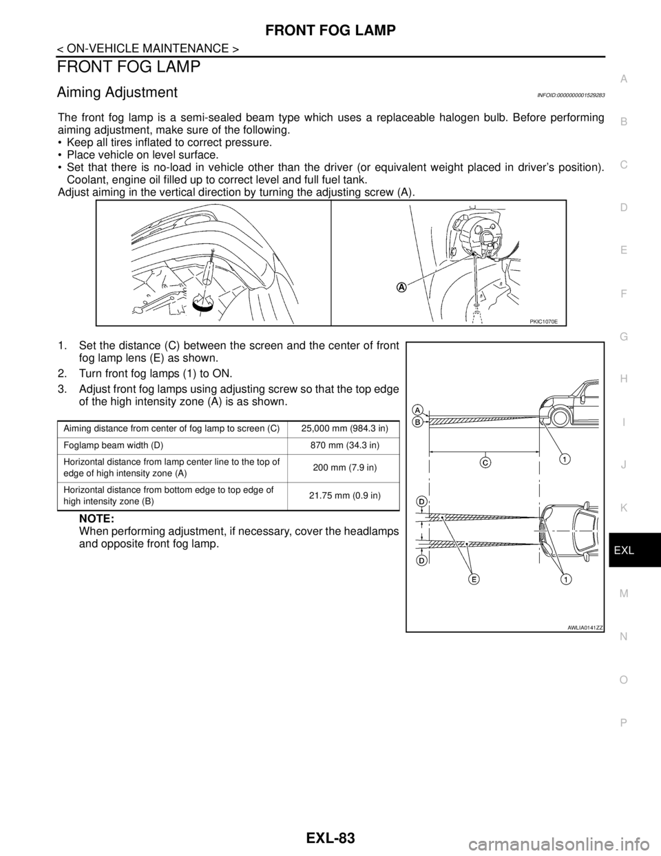
The front fog lamp is a semi-sealed beam type which uses a replaceable halogen bulb. Before performing
aiming adjustment, make sure of the following.
Keep all tires inflated to correct pressure.
Place vehicle on level surface.
Set that there is no-load in vehicle other than the driver (or equivalent weight placed in driver’s position).
Coolant, engine oil filled up to correct level and full fuel tank.
Adjust aiming in the vertical direction by turning the adjusting screw (A).
1. Set the distance (C) between the screen and the center of front
fog lamp lens (E) as shown.
2. Turn front fog lamps (1) to ON.
3. Adjust front fog lamps using adjusting screw so that the top edge
of the high intensity zone (A) is as shown.
NOTE:
When performing adjustment, if necessary, cover the headlamps
and opposite front fog lamp.
PKIC1070E
Aiming distance from center of fog lamp to screen (C) 25,000 mm (984.3 in)
Foglamp beam width (D) 870 mm (34.3 in)
Horizontal distance from lamp center line to the top of
edge of high intensity zone (A)200 mm (7.9 in)
Horizontal distance from bottom edge to top edge of
high intensity zone (B)21.75 mm (0.9 in)
AWLIA0141ZZ